patent · US5658449
Method and device for catalytic nitrogen oxide reduction of motor vehicle exhaust
19 August 1997
Page 1 — bibliographic record
United States Patent (19) 11 Patent Number: 5,658.449 Benz et al. 45 Date of Patent: Aug. 19, 1997 54 METHOD AND DEVICE FORCATALYTIC 5,176,809 1/1993 Simuni .................................... 205/637 NTROGEN OXDE REDUCTION OF 5,352.337 10/1994 Kobayashi et al. ... ... 204/59 R MOTORVEHICLE EXHAUST 5,399.251 3/1995 Nakamats ................................ 205/628 75) Inventors: Uwe Benz, Uhldingen; Ottmar FOREIGN PATENT DOCUMENTS Schmid, Markdorf, both of Germany
73) Assignee: Dornier GmbH, Friedrichshafen, O 537 968 4/1993 European Pat. Off. . Germany 0566 071 10/1993 European Pat. Off..
(21) Appl. No.: 586,004 19544 585.6 9/1995 Germany.
(22 Filed: Jan. 16, 1996 19535 212.2 11/1995 Germany. 30 Foreign Application Priority Data
Primary Examiner-Arun S. Phasge
Jan. 13, 1995 (DE) Germany ........................ 19500 788.3 Attorney, Agent, or Firm-Evenson, McKeown, Edwards & (51) Int. Cl. ...mm. C02F 1/46 Lenahan, P.L.L.C.
52 U.S. Cl. ...... ... 205/637; 205/628; 205/763; 57 ABSTRACT
(58) Field of Search .................................... 205/637, 628, Amethod and a device for NO reduction of exhaustin motor 205/763; 204/252,266, 278 vehicles by reduction on a catalyst is provided. The hydro genrequired for NO reduction is generated directly on board (56) References Cited the motor vehicle by electrolysis with liquid fixed electro lyte.
5,023,063 6/1991 Stiles ....................................... 423/239 16 Claims, 10 Drawing Sheets
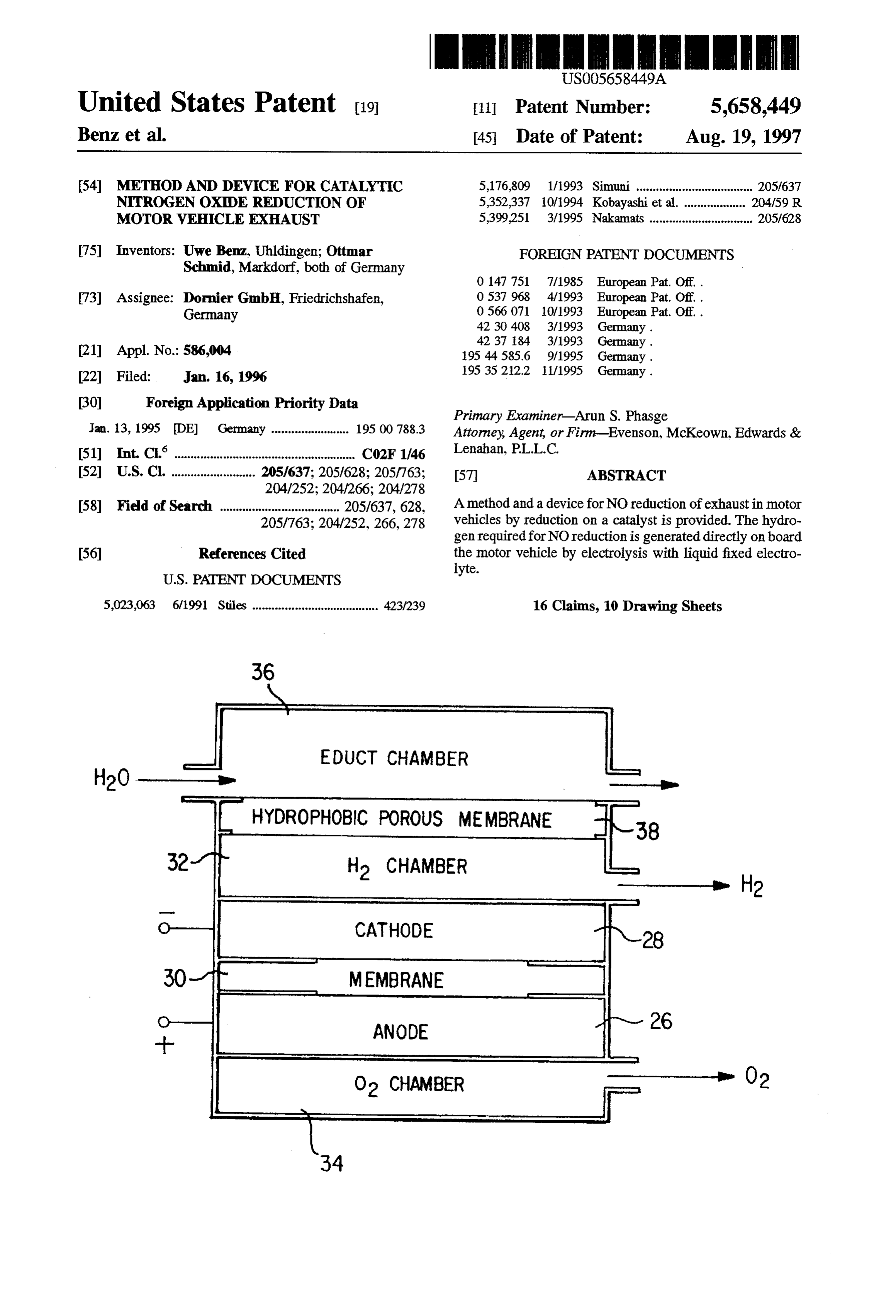
EDUCT CHAMBER
H2 CHAMBER
CATHODE
MEMBRANE
ANODE
O2 CHAMBER
Page 2
Drawing sheet — no readable text.
Page 3
Drawing sheet — no readable text.
Page 4
Drawing sheet — no readable text.
Page 5
Drawing sheet — no readable text.

Page 6
Drawing sheet — no readable text.
Page 7
Drawing sheet — no readable text.
Page 8
Drawing sheet — no readable text.
Page 9
Drawing sheet — no readable text.
Page 10
Drawing sheet — no readable text.
Page 11
Drawing sheet — no readable text.
Page 12
METHOD AND DEVICE FOR CATALYTIC (deionized water is required); and 3) the methodology is NITROGEN OXDE REDUCTION OF very expensive since the water can only be introduced MOTOR WEHICLE EXHAUST through a circuit charged with water vapor. There is therefore needed a method for NO reduction
BACKGROUND AND SUMMARY OF THE using hydrogen in a motor vehicle in which compact, INVENTION energy-efficient, mechanically loadable, and inexpensive
The invention relates to a method and a device for hydrogen generation can be performed directly aboard the motor vehicle.
catalytic reduction of nitrogen oxides for mobile applica These needs are met according to the present invention by tions and, more particularly, to a method for reducing 10 a method for reducing nitrogen oxides by reduction on a nitrogen oxides by reduction on a catalyst, with the hydro catalyst, with the hydrogen required for nitrogen reduction gen required for nitrogen reduction being generated aboard being generated aboard the motor vehicle by electrolysis. the motor vehicle by electrolysis. The electrolysis is performed using aliquid fixed electrolyte. For the operation of motor vehicles with gasoline and, These needs are further met by a device for reduction of especially, diesel engines, the observation of the applicable nitrogen oxides in motor vehicle exhaust by catalytic legal emission guidelines is indispensable. In this 5 reduction, including a reactor in which a catalyst is connection, catalytic NO reduction using hydrogen is being contained, on which nitrogen oxide reduction is performed used advantageously. with the addition of hydrogen, and at least one electrolyzer for
This catalytic removal of nitrogen oxides from the com electrolyzergenerating hydrogen aboard the motor vehicle. The bustion exhaust from motor vehicles is performed using 20 trolyte. includes an electrolyte with a liquid fixed elec hydrogen on suitable catalysts with the reaction According to the present invention, the hydrogen required for NO reduction is generated aboard the motor vehicle by
In the known method for removing nitrogen oxides by electrolysis electrolyte is using a liquid fixed electrolyte. An alkaline preferably used for this purpose. This type of
NO reduction, the hydrogen required for the reaction is 25 electrolysis is referred to in the following as LAE electroly carried in the vehicle, for example, in compressed gas tanks, liquid hydrogen tanks, or metal hydride storage devices. The sisThe (L=liquid, A=alkaline, E-electrolyte). disadvantage of this method is that large heavy containers a fixed,generation of hydrogen aboard a motor vehicle with are required to transport the hydrogen. These cumbersome advantages: 1) goodansuitability especially alkaline electrolyte, has the following for cyclic operation; 2) only containers also have a narrowly limited capacity, hence 30 minor requirements are imposed on water quality; 3) the H2 requiring short intervals between refills. In addition, the generator is suitable for operation in moving systems with filling or replacement of H2 tanks as well as the presence of out additional devices such as, for example, separators; 4) such H. tanks poses a safety problem in and of itself. low electrical power requirement due to the high efficiency; Amethod for NO reduction of exhaustin a motor vehicle 5) the manufacture of the H generator by mass production is known from European Patent document EP 0566 071 A1, 35 is inexpensive because of the simple manufacturing steps in which the required hydrogen is generated aboard the and the commercially available materials; 6) simple meth motor vehicle by electrolysis. Electrolysis is performed on odology; and 7) adaptation to the required geometry is an arrangement of electrodes between which a proton readily possible.
conducting solid electrolyte is located. The anode consists of The electrolysis of water is performed by the relationship an oxidation catalyst and the cathode consists of a reduction catalyst. NO reduction takes place directly at the cathode with the participation of the hydrogen which penetrates the HO-electrical energy-H+%0-heat solid electrolyte. in a plurality of electrolysis cells connected in parallel. The One disadvantage of this known method is that the operation of the electrolyzer uses thermoneutral voltage, so catalyst must be heated to a reaction temperature of at least 45 that heat is produced as well. The electrical power required 300° C. and is therefore not practical for gasoline and diesel for generating hydrogen can be obtained from the alternator engines, especially during the starting processes and in the in the motor vehicle. In all, a maximum electrical power partial load range. The exhaust temperatures in the partial requirement of 190 W is needed for complete reduction of load range decrease to about 100° C. at the point where the nitrogen oxides in today's automobile diesel engine exhaust. exhaust aftertreatment system is located within the motor 50 This peak power requirement however is sharply reduced by vehicle. Therefore, systems that operate above approxi an electrolyzer gas-pressure reduction. The average electri mately 100° C. require additional heating. cal power requirement can be considerably lowered by the Another disadvantage of the known method is that the short response times of electrolysis by demand-oriented H2 method has a low efficiency. The H gas stream that is generation using an already existing accelerator potentiom generated is less than 1 ml/min. In the vehicle, however, a 55 etc.
H. gas stream of at least 0.2-0.71/min is required. If it were The relatively low water requirement is met by a separate desired to use this method in a conventional diesel-powered water container. Advantageously, the water can also be vehicle, an electrode with a diameter of more than 1 meter supplied through the water-vapor-charged engine exhaust (approximately 3 m electrode surface) would be required. from the motor vehicle.
German Patent document DE 42 30 408 A1 describes a It is a further advantage of the present invention that method for NO reduction of exhaustin an internal combus separate tempering for the electrolyzer is not required. Heat tion engine in which the required hydrogen is generated by exchange with the environment is sufficient because of the electrolysis of water using a proton-conducting membrane. simple and flexible operating mode of the electrolyzer. The This method has the following disadvantages: 1) under operating temperature range of the electrolyzer is between freezing conditions, additional heating of the electrolyzer is 65 -25° C. and 95° C.
required to keep the membrane from being destroyed; 2) The electrolyzer can be operated at variable pressure, so high requirements are imposed on the water quality that very rapid load changes are advantageously possible.
Page 13
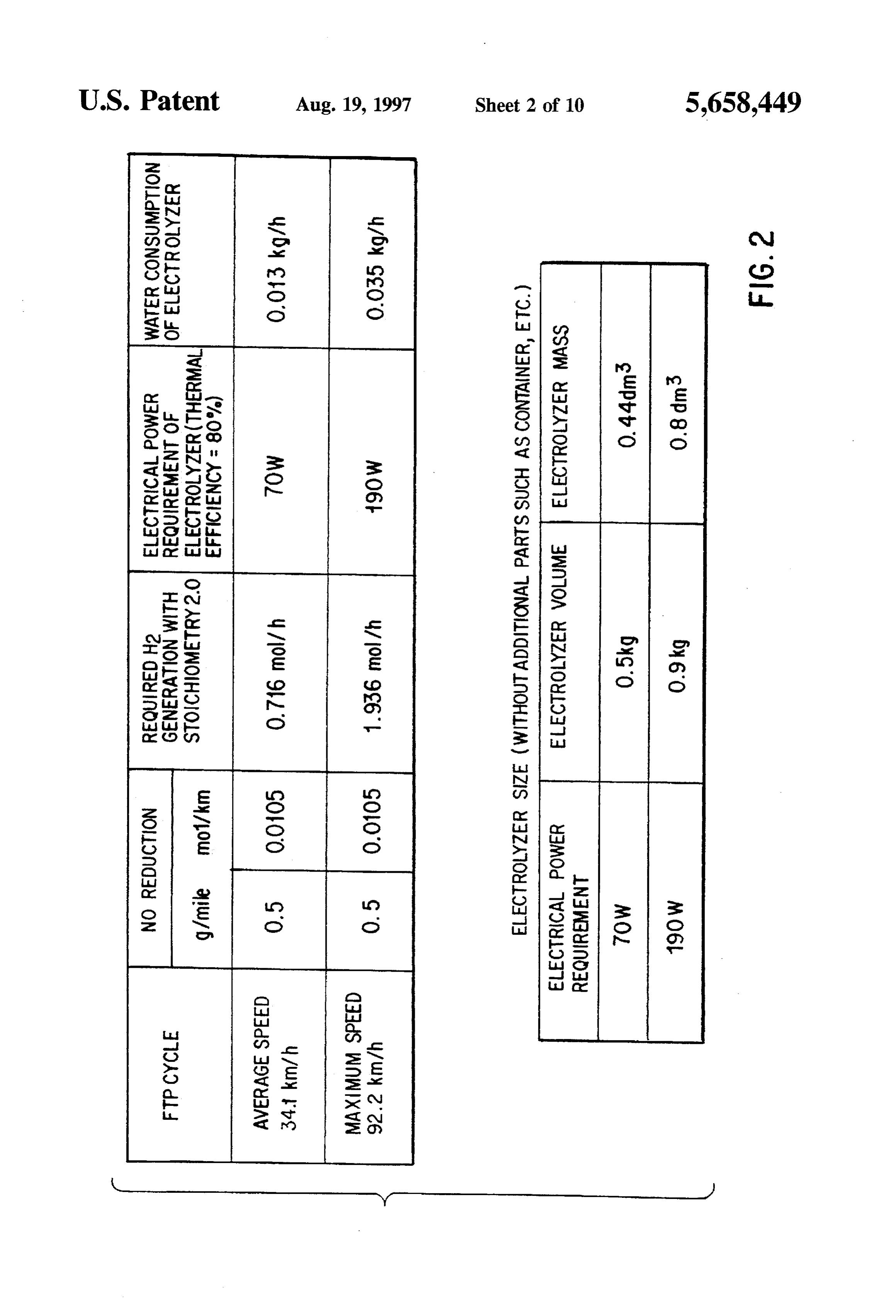
In one especially advantageous embodiment, the reduction of the NO components in diesel engine exhaust to hydrogen, in addition to electrolysis using fixed liquid solid between 0.7 g/mile and 0.2 g/mile; 2) the USAFTP75 test electrolyte, is also generated by water vapor reformation cycle is critical in the United States, with an average speed and/or partial oxidation of hydrocarbons, for example of 34.1 km/h and a maximum speed of 92.2 km/h; and 3) methanol, diesel fuel, or gasoline. Hydrogen generation by surplus of H (stoichiometry) relative to NO of 2.0. partial oxidation or reformation of hydrocarbons aboard a On the basis of these boundary conditions, the values motor vehicle in and of itself is known from European Patent shown in the table of FIG. 2 are obtained for the electrical document EP 0537 968 A1. power requirement of the electrolyzer and the water con In this case, the device for generating hydrogen Sumption. Also shown are the values for the resultant comprises, in addition to an electrolyzer with a liquid fixed 10 dimensions of the electrolyzer. It should be noted in con solid electrolyte, a reactor for water vapor reformation junction with the values in the table that they were calculated and/or a reactor for partial oxidation of hydrocarbons. Such assuming represents 100% NO in the total value of NO. Since NO the dominant share in the total value of NO, this hybrid systems are especially advantageous for applications that have a high hydrogen requirement and require short simplification
The first is justified.
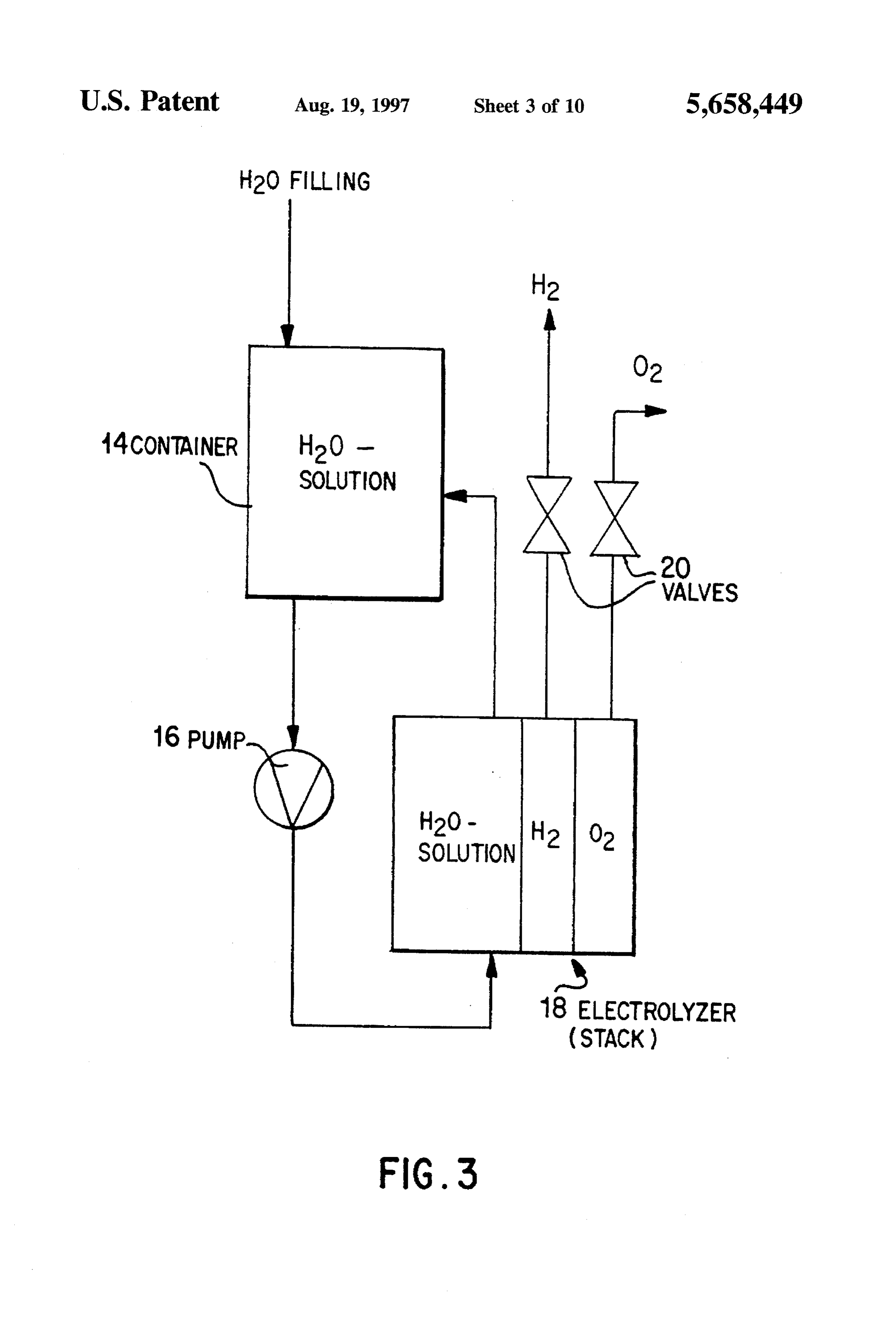
embodiment shown in FIG. 3 includes a con response times for a cold start and load changes. 15 tainer 14 for storing the aqueous solution. The aqueous
Other objects, advantages and novel features of the solution constitutes the educt present invention will become apparent from the following solution of salts of inorganic for and electrolysis. An aqueous organic acids (acetates, detailed description of the invention when considered in phosphates, etc.) or mixtures of water with organic additives conjunction with the accompanying drawings. (glycols, urea, and glycerine for example) may, for example, 20 be used. In addition, however, H2O can be used instead of
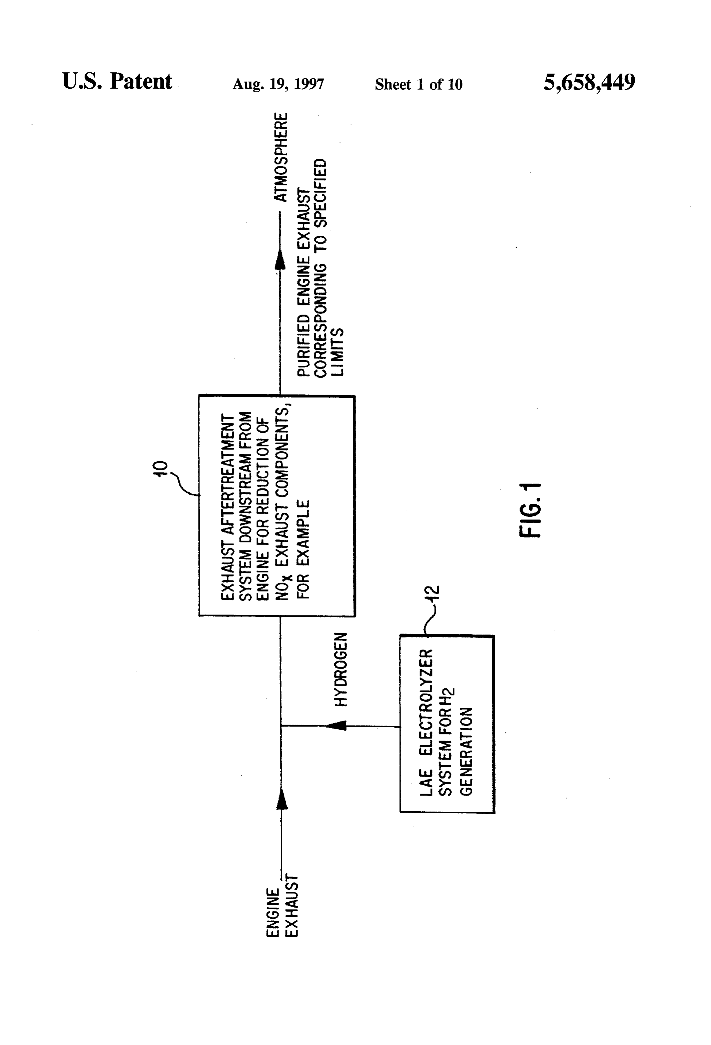
BRIEF DESCRIPTION OF THE DRAWINGS an aqueous solution. The aqueous solution in the container FIG. 1 is a basic schematic diagram of catalytic NO 14 is delivered by a pump 16 to the LAE electrolyzer 18.The reduction; latter is shown only schematically here. Advantageously, it consists of a plurality of individual cells connected in series,
FIG. 2 is a table showing the electrical power requirement 25 assembled into a stack. An LAE electrolyzer cell as well as as well as water consumption and size of the electrolyzer; its operation are known of themselves. They are described FIG. 3 shows a first embodiment for generating H. for example in German Patent documents DE 19535 212.2 according to the invention using LAE electrolysis; and DE 19544 585.6. An example of an LAE electrolysis FIG. 4 shows a second embodiment for generating H. cell is shown in FIG. 6. A valve 20 is mounted at the O and according to the invention using LAE electrolysis; 30 H2 outlets of the electrolyzer. The aqueous solution is guided FIG. 5 shows a third embodiment for generating H. in a circuit, namely from the container 14 through the electrolyzer stack 18 and back to the container 14. In this according to the invention using LAE electrolysis; way, homogenization of the temperature as well as concen FIG. 6 shows a schematic diagram of an electrolyzer with tration of the aqueous solution can be ensured. a liquid fixed electrolyte; 35 In order to compensate for the water losses that result FIG. 7 is a schematic diagram showing H generation by during electrolysis, water can be supplied to the container at water vapor reformation from methanol; Zero pressure. Water of tap water quality can be used for this FIG. 8 shows a reactor for performing water vapor purpose. However, the container must not be topped up until reformation from methanol; after concentration of the aqueous solution to the maximum FIG. 9 is a schematic diagram showing H generation by permissible boundary value has taken place as a result of the partial oxidation of methanol; and water losses. The product gases generated by the electrolyzer, namely oxygen and hydrogen, are exhausted
FIG. 10 shows a reactor for performing partial oxidation through from methanol. the valves at corresponding pressures. These valves also prevent gases and liquids from flowing backward. The
DEALED DESCRIPTION OF THE DRAWINGS 45 electrical power requirement can be met by the alternator in the vehicle. The average power requirement can be sharply
FIG. 1 shows the general diagram of the process for decreased by demand-optimized control of the H catalytic reduction of nitrogen oxides in engine exhaust. The generation, for example, by parallel tapping of an existing engine exhaustis fed to an exhaust aftertreatment system 10 signal at the potentiometer for the accelerator control of the arranged downstream from the engine for reduction of NO 50 motor vehicle. Especially with a lower H requirement (for exhaust components. Likewise, hydrogen is also fed to the example in the version with a 70 W electrical power exhaust aftertreatment system from an LAE electrolyzer requirement for the electrolyzer) the delivery pump 16 can system 12 for H generation. The purified engine exhaust be eliminated. Homogenization of the temperature and con corresponding to specified limits exits the aftertreatment centration of the aqueous solution are ensured by the system 10 into the atmosphere. The present invention thus 55 process-governed cell-internal heating of the electrolyzer. relates to the generation of hydrogen, required for NO This heating causes a change in the density of the aqueous reduction. According to the invention, the hydrogen is solution, hence resulting in mixing.
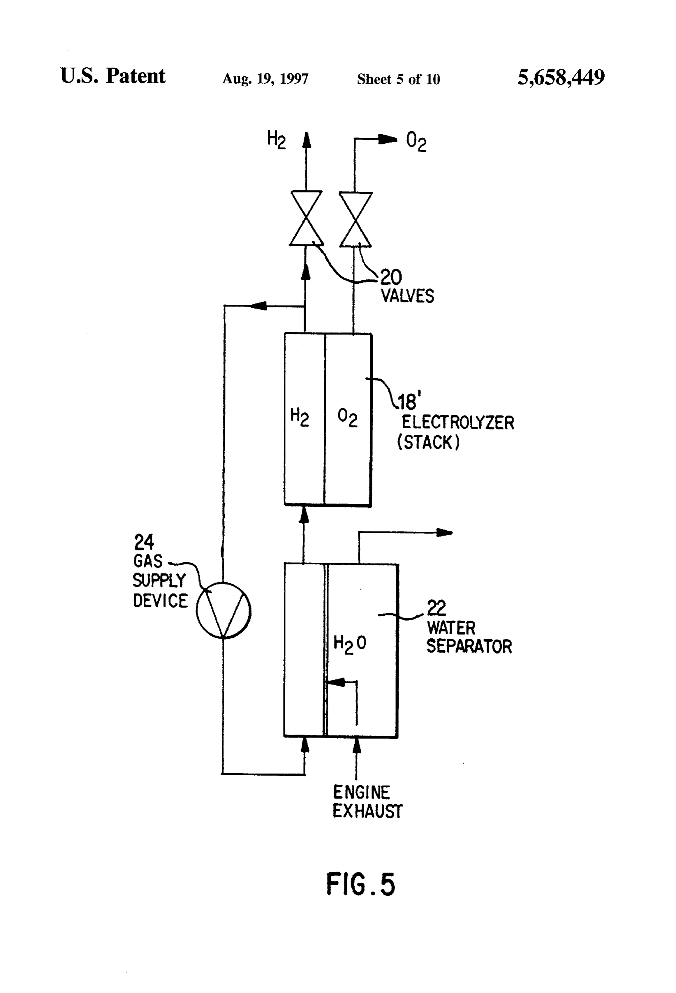
generated by electrolysis using fixed, preferably alkaline, In the embodiment shown in FIG. 4, the water for electrolytes. electrolysis is taken from the water-vapor-loaded engine FIGS. 3-5 show various designs according to the present exhaust. As a result, there is no need for topping-off a invention for generating H by LAE electrolysis on board container with water as in the embodiment shown in FIG. 3. the vehicle. These embodiments meet the requirements A separator 22 is provided to separate the water from the imposed on the H supply within the method shown in FIG. engine exhaust. The water collected in the separator 22 is fed 1 for reaching the legally prescribed NO limits. directly into the circuit for the aqueous solution, which The embodiments shown in FIGS. 3-5, in addition to the 65 constitutes the educt for the electrolysis. Otherwise, the requirement relating to their suitability in motor vehicles, design shown corresponds to the embodiment depicted in are also subject to the following boundary conditions: 1) FIG. 3.
Page 14
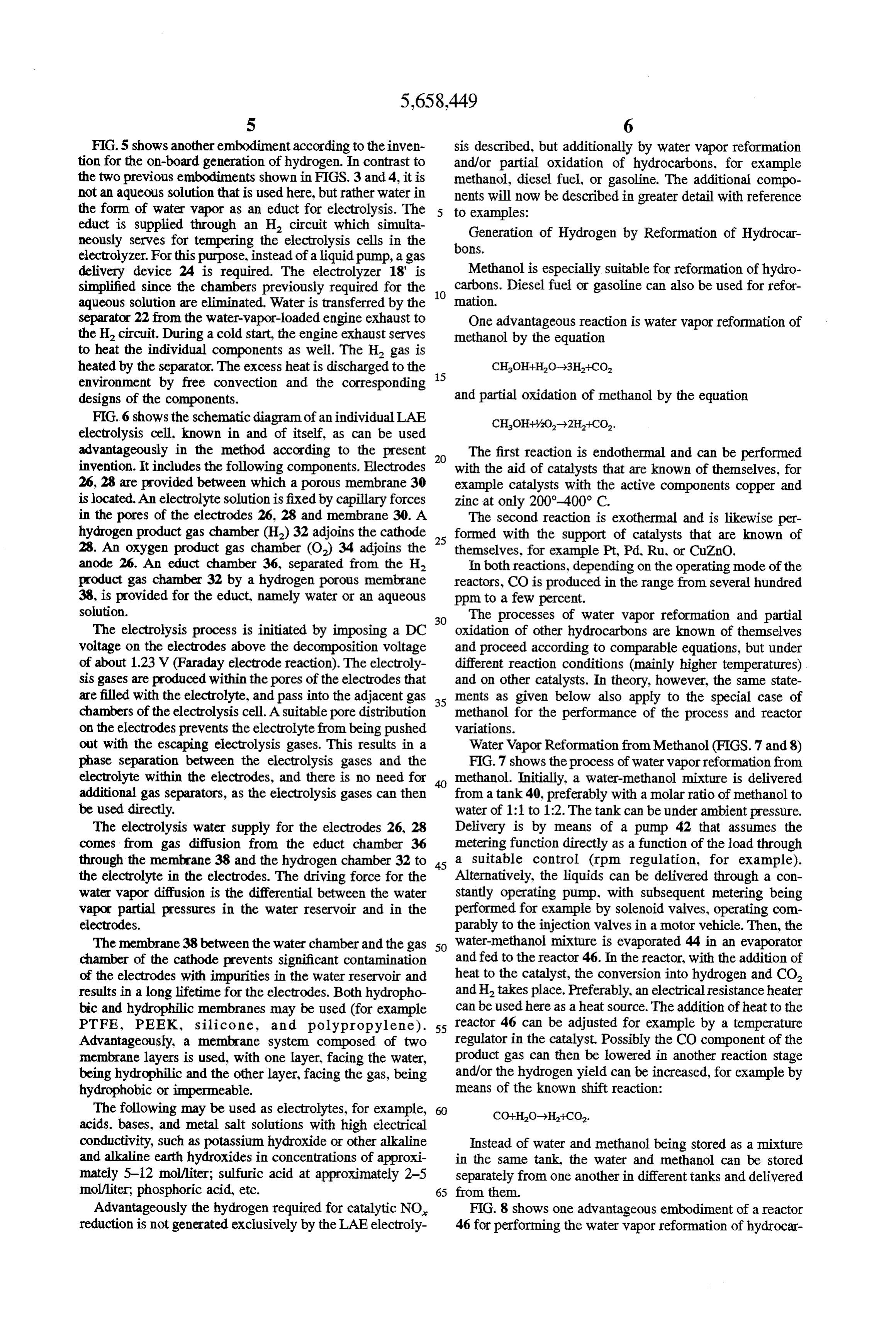
FIG.5 shows another embodiment according to the inven sis described, but additionally by water vapor reformation tion for the on-board generation of hydrogen. In contrast to and/or partial oxidation of hydrocarbons, for example the two previous embodiments shown in FIGS. 3 and 4, it is methanol, diesel fuel, or gasoline. The additional compo not an aqueous solution that is used here, but rather water in nents will now be described in greater detail with reference the form of water vapor as an educt for electrolysis. The to examples:
educt is supplied through an H. circuit which simulta Generation of Hydrogen by Reformation of Hydrocar neously serves for tempering the electrolysis cells in the electrolyzer. For this purpose, instead of a liquid pump, a gas bons.
delivery device 24 is required. The electrolyzer 18' is Methanol is especially suitable for reformation of hydro simplified since the chambers previously required for the 10 carbons. Diesel fuel or gasoline can also be used for refor aqueous solution are eliminated. Water is transferred by the mation.
separator 22 from the water-vapor-loaded engine exhaust to One advantageous reaction is water vapor reformation of the H. circuit. During a cold start, the engine exhaust serves methanol by the equation to heat the individual components as well. The H gas is heated by the separator. The excess heat is discharged to the 5 CHOH-HO-3H-CO, environment by free convection and the corresponding designs of the components. and partial oxidation of methanol by the equation FIG. 6 shows the schematic diagram of an individual LAE CHOH+%O-2H+CO.
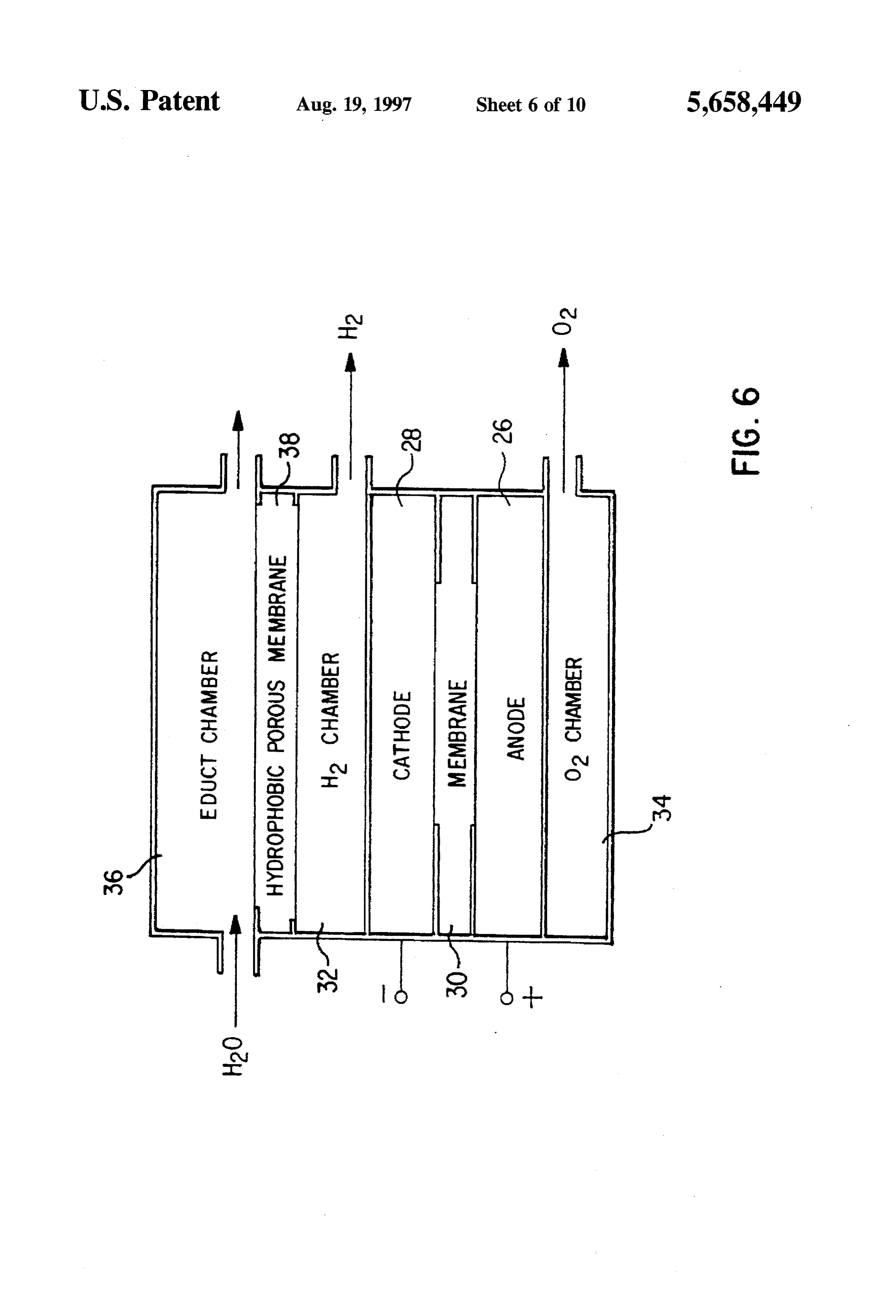
electrolysis cell, known in and of itself, as can be used advantageously in the method according to the present The first reaction is endothermal and can be performed invention. It includes the following components. Electrodes 20 with the aid of catalysts that are known of themselves, for 26, 28 are provided between which a porous membrane 30 example catalysts with the active components copper and is located. An electrolyte solution is fixed by capillary forces zinc at only 200-400° C.
in the pores of the electrodes 26, 28 and membrane 30. A The second reaction is exothermal and is likewise per hydrogen product gas chamber (H2)32 adjoins the cathode 25 formed with the support of catalysts that are known of 28. An oxygen product gas chamber (O) 34 adjoins the themselves, for example Pt, Pd, Ru, or CuZnO. anode 26. An educt chamber 36, separated from the H2 In both reactions, depending on the operating mode of the product gas chamber 32 by a hydrogen porous membrane reactors, CO is produced in the range from several hundred 38, is provided for the educt, namely water or an aqueous ppm to a few percent.
solution. The processes of water vapor reformation and partial The electrolysis process is initiated by imposing a DC 30 oxidation of other hydrocarbons are known of themselves voltage on the electrodes above the decomposition voltage and proceed according to comparable equations, but under of about 1.23 V (Faraday electrode reaction). The electroly different reaction conditions (mainly higher temperatures) sis gases are produced within the pores of the electrodes that and on other catalysts. In theory, however, the same state are filled with the electrolyte, and pass into the adjacent gas 35 ments as given below also apply to the special case of chambers of the electrolysis cell. A suitable pore distribution methanol for the performance of the process and reactor on the electrodes prevents the electrolyte from being pushed variations.
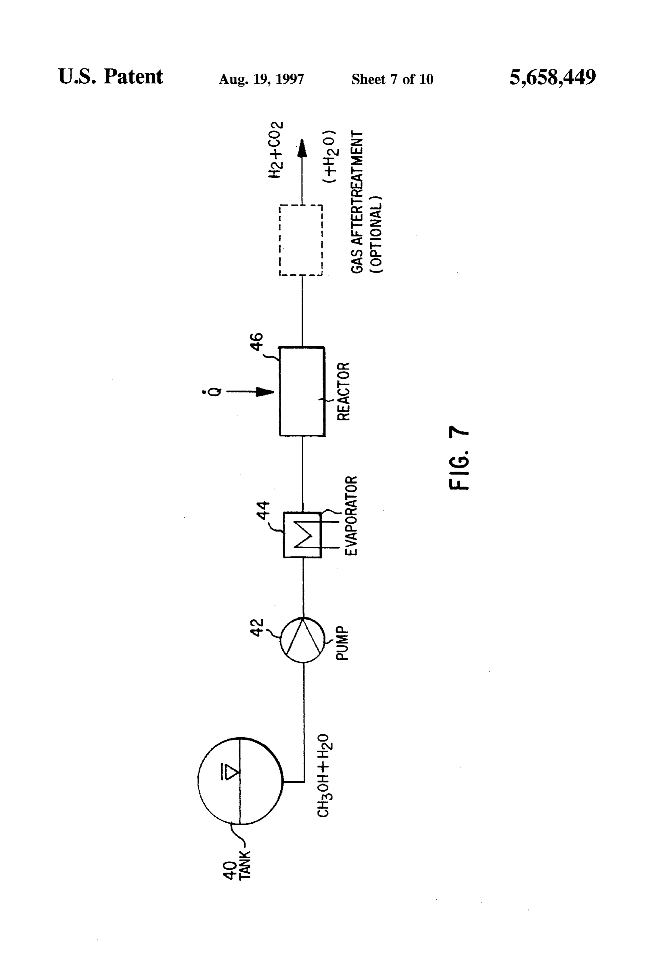
out with the escaping electrolysis gases. This results in a Water Vapor Reformation from Methanol (FIGS. 7 and 8) phase separation between the electrolysis gases and the FIG.7 shows the process of water vapor reformation from electrolyte within the electrodes, and there is no need for methanol. Initially, a water-methanol mixture is delivered additional gas separators, as the electrolysis gases can then from a tank 40, preferably with a molar ratio of methanol to be used directly. water of 1:1 to 1:2. The tank can be under ambient pressure. The electrolysis water supply for the electrodes 26, 28 Delivery is by means of a pump 42 that assumes the comes from gas diffusion from the educt chamber 36 metering function directly as a function of the load through through the membrane 38 and the hydrogen chamber 32 to 45 a suitable control (rpm regulation, for example). the electrolyte in the electrodes. The driving force for the Alternatively, the liquids can be delivered through a con water vapor diffusion is the differential between the water stantly operating pump, with subsequent metering being vapor partial pressures in the water reservoir and in the performed for example by solenoid valves, operating com electrodes. parably to the injection valves in a motor vehicle. Then, the The membrane 38 between the water chamber and the gas 50 water-methanol mixture is evaporated 44 in an evaporator chamber of the cathode prevents significant contamination and fed to the reactor 46. In the reactor, with the addition of of the electrodes with impurities in the water reservoir and heat to the catalyst, the conversion into hydrogen and CO results in a long lifetime for the electrodes. Both hydropho and H. takes place. Preferably, an electrical resistance heater bic and hydrophilic membranes may be used (for example can be used here as a heat source. The addition of heat to the PTFE, PEEK, silicone, and polypropylene). 55 reactor 46 can be adjusted for example by a temperature Advantageously, a membrane system composed of two regulator in the catalyst. Possibly the CO component of the membrane layers is used, with one layer, facing the water, product gas can then be lowered in another reaction stage being hydrophilic and the other layer, facing the gas, being and/or the hydrogen yield can be increased, for example by hydrophobic or impermeable. means of the known shift reaction: The following may be used as electrolytes, for example, acids, bases, and metal salt solutions with high electrical conductivity, such as potassium hydroxide or other alkaline Instead of water and methanol being stored as a mixture and alkaline earth hydroxides in concentrations of approxi in the same tank, the water and methanol can be stored mately 5-12 mol/liter; sulfuric acid at approximately 2-5 separately from one another in different tanks and delivered mol/liter; phosphoric acid, etc. 65 from them.
Advantageously the hydrogen required for catalytic NO FIG. 8 shows one advantageous embodiment of a reactor reduction is not generated exclusively by the LAE electroly 46 for performing the water vapor reformation of hydrocar
Page 15
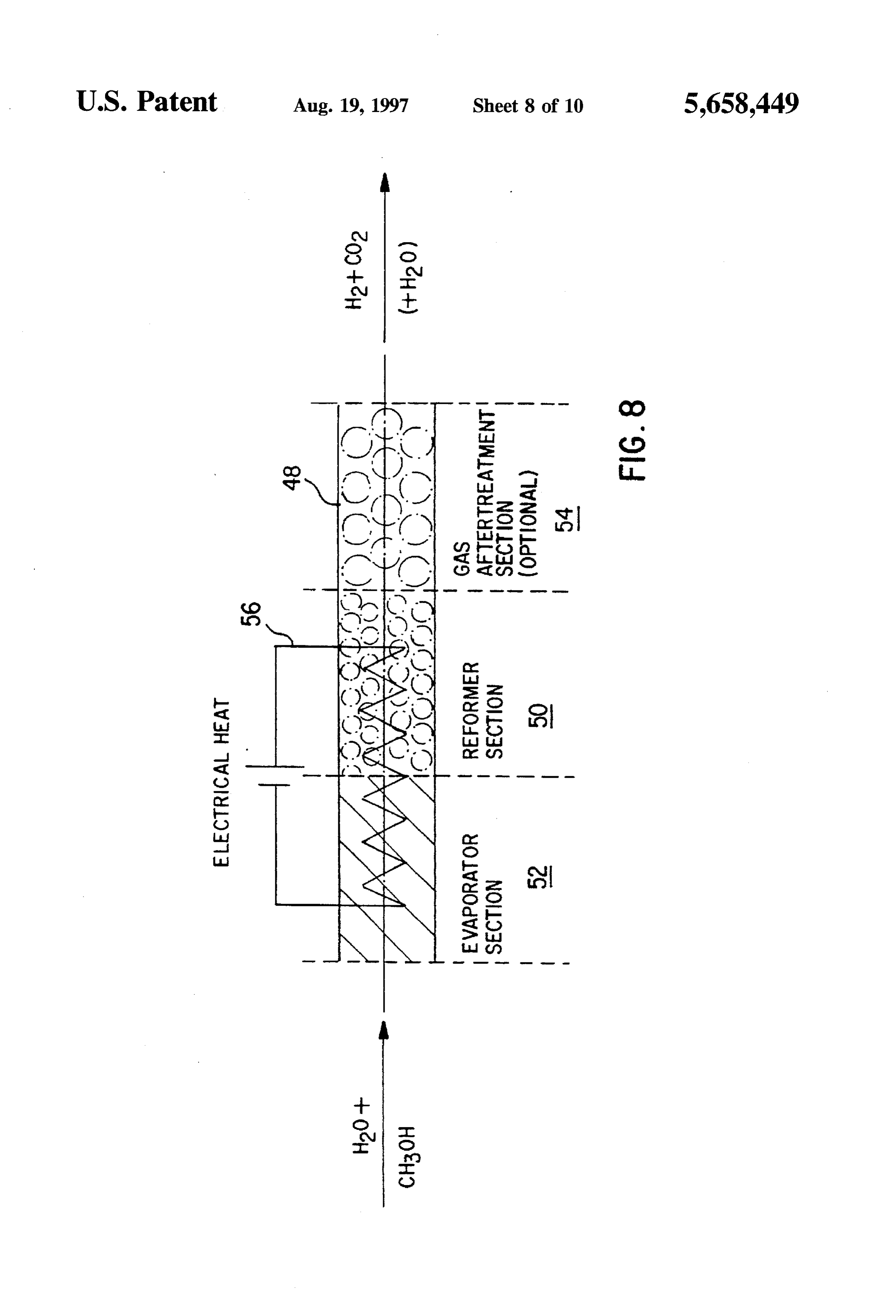
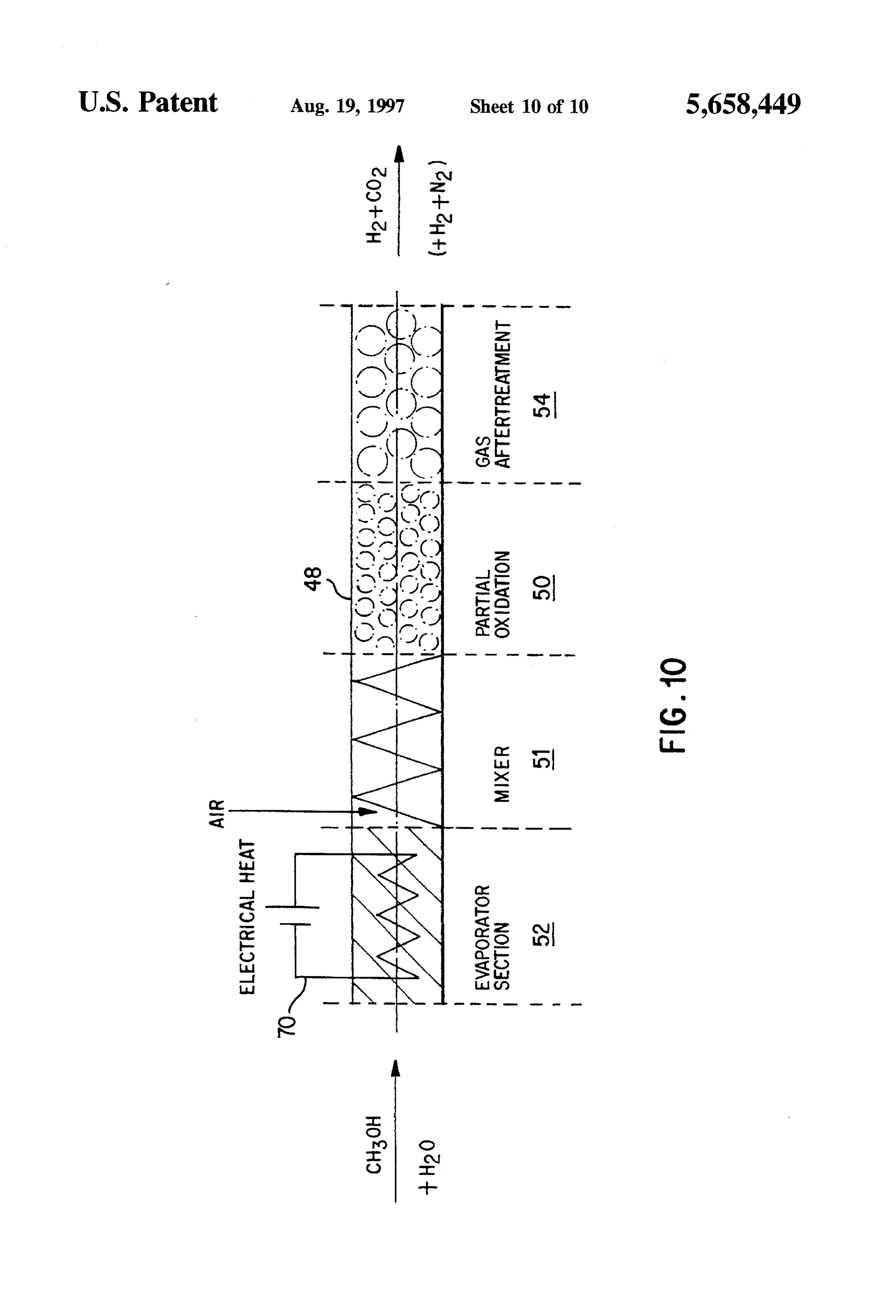
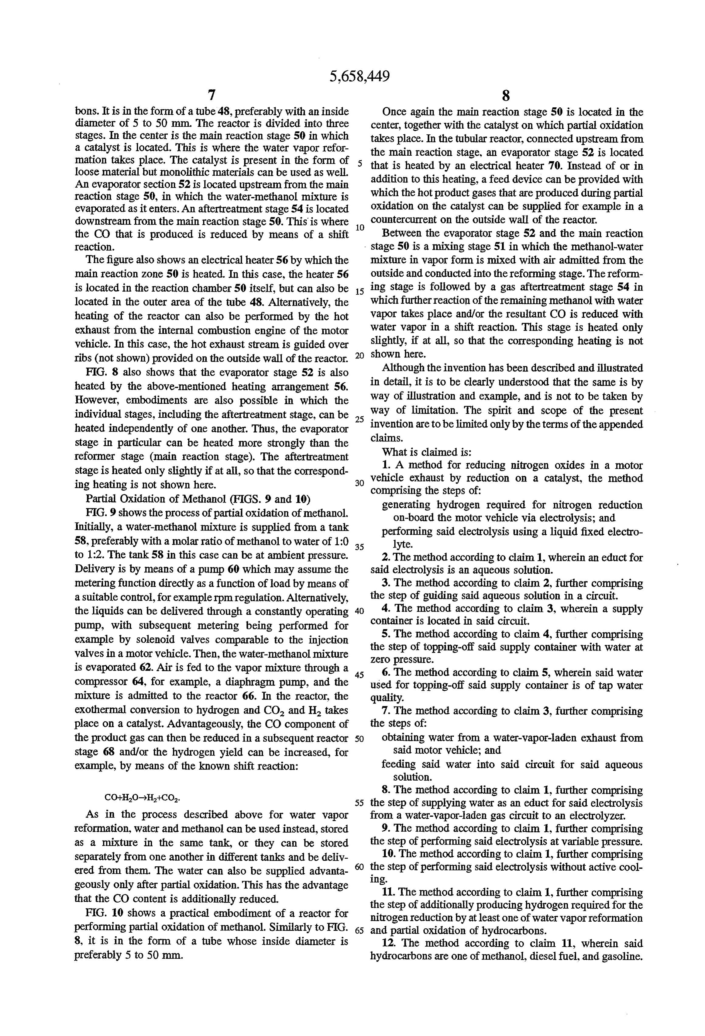
bons. It is in the form of a tube 48, preferably with an inside Once again the main reaction stage 50 is located in the diameter of 5 to 50 mm. The reactor is divided into three center, together with the catalyst on which partial oxidation stages. In the center is the main reaction stage 50 in which takes place. In the tubular reactor, connected upstream from a catalyst is located. This is where the water vapor refor the main reaction stage, an evaporator stage 52 is located mation takes place. The catalyst is present in the form of that is heated by an electrical heater 70. Instead of or in loose material but monolithic materials can be used as well.
An evaporator section 52 is located upstream from the main addition to this heating, a feed device can be provided with reaction stage 50, in which the water-methanol mixture is which the hot product gases that are produced during partial evaporated as it enters. An aftertreatment stage 54 is located oxidation on the catalyst can be supplied for example in a downstream from the main reaction stage 50. This is where 10 countercurrent on the outside wall of the reactor. the CO that is produced is reduced by means of a shift Between the evaporator stage 52 and the main reaction reaction. stage 50 is a mixing stage 51 in which the methanol-water The figure also shows an electrical heater 56 by which the mixture in vapor form is mixed with air admitted from the main reaction zone 50 is heated. In this case, the heater 56 outside and conducted into thereforming stage. The reform is located in the reaction chamber 50 itself, but can also be 15 ing stage is followed by a gas aftertreatment stage 54 in located in the outer area of the tube 48. Alternatively, the which further reaction of the remaining methanol with water heating of the reactor can also be performed by the hot vapor takes place and/or the resultant CO is reduced with exhaust from the internal combustion engine of the motor water vapor in a shift reaction. This stage is heated only vehicle. In this case, the hot exhaust stream is guided over shown slightly, if at all, so that the corresponding heating is not here.
ribs (not shown) provided on the outside wall of the reactor. 20
FIG. 8 also shows that the evaporator stage 52 is also Although the invention has been described and illustrated heated by the above-mentioned heating arrangement 56. in detail, it is to be clearly understood that the same is by However, embodiments are also possible in which the way of illustration and example, and is not to be taken by individual stages, including the aftertreatment stage, can be 25 way of limitation. The spirit and scope of the present heated independently of one another. Thus, the evaporator inventionclaims.
are to be limited only by the terms of the appended stage in particular can be heated more strongly than the What is claimed is:
reformer stage (main reaction stage). The aftertreatment 1. A method for reducing nitrogen oxides in a motor stage is heated only slightly if at all, so that the correspond ing heating is not shown here. 30 vehicle exhaust by reduction on a catalyst, the method comprising the steps of:
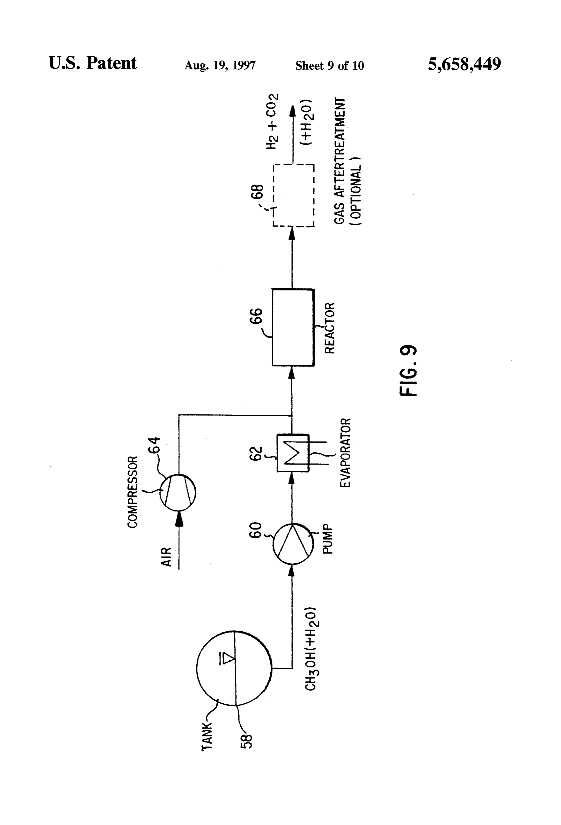
Partial Oxidation of Methanol (FIGS. 9 and 10) generating hydrogen required for nitrogen reduction FIG. 9 shows the process of partial oxidation of methanol. on-board the motor vehicle via electrolysis; and Initially, a water-methanol mixture is supplied from a tank performing said electrolysis using a liquid fixed electro 58, preferably with a molar ratio of methanol to water of 1:0 35 lyte.
to 1:2. The tank 58 in this case can be at ambient pressure. 2. The method according to claim 1, wherein an educt for Delivery is by means of a pump 60 which may assume the said electrolysis is an aqueous solution.
metering function directly as a function of load by means of 3. The method according to claim 2, further comprising a suitable control, for example rpm regulation. Alternatively, the step of guiding said aqueous solution in a circuit. the liquids can be delivered through a constantly operating 40 4. The method according to claim 3, wherein a supply pump, with subsequent metering being performed for container is located in said circuit. example by solenoid valves comparable to the injection 5. The method according to claim 4, further comprising valves in a motor vehicle. Then, the water-methanol mixture the step of topping-off said supply container with water at Zero pressure.
is evaporated 62. Air is fed to the vapor mixture through a 45 6. The method according to claim 5, wherein said water compressor 64, for example, a diaphragm pump, and the used for topping-off said supply container is of tap water mixture is admitted to the reactor 66. In the reactor, the quality.
exothermal conversion to hydrogen and CO and H2 takes 7. The method according to claim 3, further comprising place on a catalyst. Advantageously, the CO component of the steps of:
the product gas can then be reduced in a subsequent reactor 50 obtaining water from a water-vapor-laden exhaust from stage 68 and/or the hydrogen yield can be increased, for said motor vehicle; and example, by means of the known shift reaction: feeding said water into said circuit for said aqueous Solution.
8. The method according to claim 1, further comprising 55 the step of supplying water as an educt for said electrolysis
As in the process described above for water vapor from a water-vapor-laden gas circuit to an electrolyzer. reformation, water and methanol can be used instead, stored 9. The method according to claim 1, further comprising as a mixture in the same tank, or they can be stored the step of performing said electrolysis at variable pressure. separately from one another in different tanks and be deliv 10. The method according to claim 1, further comprising ered from them. The water can also be supplied advanta Ing.step of performing said electrolysis without active cool the geously only after partial oxidation. This has the advantage 11. The method according to claim 1, further comprising that the CO content is additionally reduced. the step of additionally producing hydrogen required for the FIG. 10 shows a practical embodiment of a reactor for nitrogen reduction by at least one of water vapor reformation performing partial oxidation of methanol. Similarly to FIG. 65 and partial oxidation of hydrocarbons. 8, it is in the form of a tube whose inside diameter is 12. The method according to claim 11, wherein said preferably 5 to 50 mm. hydrocarbons are one of methanol, diesel fuel, and gasoline.
Page 16
13. A device for reducing nitrogen oxides in motor vehicle generating hydrogen via electrolysis using a liquid fixed exhaust via catalytic reduction, comprising: electrolyte on board the motor vehicle; and a reactor in which a catalyst is contained, nitrogen oxide independently performing nitrogen reduction on-board reduction being performed on said catalyst with the the motor vehicle using said generated hydrogen. addition of hydrogen; 5 16. A device for reducing nitrogen oxides in motor vehicle exhaust via catalytic reduction, comprising:
at least one electrolyzerfor generating hydrogen on-board a reactor in which a catalyst is contained, nitrogen oxide said motor vehicle, wherein said electrolyzer includes reduction being performed on said catalyst; and an electrolyte having a liquid fixed electrolyte. at least one electrolyzer for separately generating hydro 14. The device according to claim 13, further comprising 10 gen on-board said motor vehicle apart from the reactor, at least one of a first reactor for water vapor reformation wherein said electrolyzer includes an electrolyte having from hydrocarbons and a second reactor for partial oxidation a liquid fixed electrolyte, and wherein said hydrogen is of hydrocarbons for generating hydrogen. coupled with said reactor to perform said nitrogen 15. A method for reducing nitrogen oxides in a motor oxide reduction.
vehicle exhaust by reduction on a catalyst, the method comprising the steps of:
Provenance
- Collection
- Cited prior art
- Original PDF
- patentimages.storage.googleapis.com →
- Filed
- 1996-01-16
- Pages
- 16
- Method
- pdftotext (the PDF's own text layer) + pdftoppm 300dpi page scans
- Source
- Google Patents bibliographic record
- Granted
- 1997-08-19
- Inventors
- Uwe Benz; Ottmar Schmid; Dornier GmbH
- Transcribed from
- patentimages.storage.googleapis.com →