patent · US5813222
Method and apparatus for heating a catalytic converter to reduce emissions
29 September 1998
Page 1 — bibliographic record
United States Patent (19) 11 Patent Number: 5,813,222 Appleby (45) Date of Patent: Sep. 29, 1998 54 METHOD AND APPARATUS FOR HEATING 5,163,290 11/1992 Kinnear . A CATALYTIC CONVERTER TO REDUCE 5,184,462 2/1993 Schatz. EMISSIONS 5,207,734 5/1993 Day et al..
76 Inventor: Anthony John Appleby, 2810 Briar 5,259,190 11/1993 Bagley et al.. Creek Crt., Bryan, Tex. 77802 5,272,871 12/1993 Oshima ..................................... 60/275 •s s a wa a• 5,419,121 5/1995 Sung ......................................... 60/286 21 Appl. No.: 320,171 FOREIGN PATENT DOCUMENTS 22 Filed: Oct. 7, 1994 3. "'E Ny 6 4103668 8/1992 Germany . 51) Int. Cl. ........................................................ F01N 3/20 4420715 1/1995 G y ermany .
52 U.S. Cl. ................................. 60/274; 60/284; '93; 4318214 11/1992 Japan.
58 Field of Search .............................. 60/274, 275, 286, 60/303, 301, 284; 123/3, 1 A Primary Examiner Douglas Hart
A mixture of hydrogen and air is introduced onto the face of
3,311,097 3/1967 Mittelstaedt .............................. 60/275 line of a cold internal combustion engine. The hydrogen 3,648,668 3/1972 Pacheco .................................. 123/1 A Spontaneously combusts, thereby pre-heating the catalytic 3,719,457 3/1973 Nagamatsu. converter. Pre-heating the catalytic converter significantly 3,729,936 5/1973 DePalma et al.. improves the effectiveness of the catalytic converter in 3,761.229 9/1973 Schwartz - - - - - - - - - - - - - - - - - - - - - - - - - - - - - - - - - - - 60/300 eliminating undesirable emissions of the internal combus 3,779,014 12/1973 Nohira ...................................... 60/286 tion engine. The hydrogen is preferably produced on-board 3,911,675 10/1975 Mondt ....................................... 60/300 the vehicle using the SVStem. The hvdrogen Source mav also 4,332,219 6/1982 Gonzalez .................................... 123/3 led t E. t y combusti yaroge to be b y db 4,499,864 2/1985 Lovercheck et al.. e coupled to Ine Internal combustion engine to be burned by 4,763,610 8/1988 Thomas ....................................... 1233 the engine during startup in the absence of gasoline to 4,865,818 9/1989 Merry et al.. minimize the production of unacceptable emissions while 4,985,210 1/1991 Minami. the catalyst is brought up to light-off temperature.
5,155,995 10/1992 Kinnear et al.. 62 Claims, 8 Drawing Sheets
Page 2
Drawing sheet — no readable text.
Page 3
Drawing sheet — no readable text.
Page 4
Drawing sheet — no readable text.
Page 5
Drawing sheet — no readable text.
Page 6
Drawing sheet — no readable text.
Page 7
Q O lo to S
s s S S S S is siss
-- TEMPERATURE (OC)
l?) s S Y - an J S (Y - S. l H - s
O O O Q O O O Q O s
-- TEMPERATUREE. (C)
Page 8
Drawing sheet — no readable text.
Page 9
Drawing sheet — no readable text.
Page 10
METHOD AND APPARATUS FOR HEATING the light-off time. Light-off temperature is generally defined A CATALYTIC CONVERTER TO REDUCE as the temperature at which fifty percent (50%) of the EMISSIONS emissions from the engine are being converted as they pass through the catalyst.
BACKGROUND OF THE INVENTION The conventional method of heating the catalytic con Field of the Invention verter is to heat the catalyst by contact with high temperature exhaust gases from the engine. This heating, in conjunction
The present invention relates generally to the field of with the exothermic nature of the oxidation reaction occur catalysis for the reduction of emissions from internal com ring at the catalyst, will bring the catalyst to light-off bustion engines. More particularly, the present invention temperature. However, until the light-off temperature is relates to a method and apparatus for heating a catalyst by reached, the exhaust gas passes through the catalyst rela Spontaneous combustion of hydrogen introduced into the tively unchanged. In addition, the composition of the engine catalyst. More particularly Still, the present invention relates exhaust changes as the engine heats from the cold Start to the conditioning through preheating of a Standard three temperature, and the catalyst is designed to work best with way or two-way catalytic monolith in a vehicle powered by 15 the composition of the exhaust Stream present at the normal an internal combustion engine, Such as an automobile. elevated engine operating temperature. The control and Suppression of unwanted emissions cre There have been several attempts to shorten or avoid the ated by the operation of an internal combustion engine is a time between cold Start and light-off of the catalytic con primary consideration for engine designers and vehicle verter. Current techniques employ one or more of the manufacturers because of nearly world-wide governmental following methods: electrical heating of the exhaust gases requirements regarding acceptable emission levels. Over and/or of the catalytic converter itself; thermal insulation; eighty percent (80%) of the unacceptable emissions or multi-chambered configurations of the catalytic converter; pollutants created by internal combustion engines equipped and/or placing the catalytic converter adjacent to the engine with catalytic converters occur during cold Start operations. 25 for heating. All of these methods have drawbacks and These pollutants are emitted for a period of one to three limitations.
minutes after cold engine Starting, in large part because that Placing the catalytic converter almost immediately adja is the time period required for the catalyst to reach an cent to the engine is not feasible because of the tendency to efficient operating temperature. Therefore, even though the overheat the catalyst with resulting accelerated degradation engine exhaust is flowing through the catalytic converter, of the catalyst due to excessive heat. Thermal insulation is until the exhaust heats the catalytic converter to its operating also not an acceptable option because of the same problems, range from engine Start up, the exhaust flow is only slightly especially during operation under maximum operating tem catalyzed during that time period. perature ranges.
In order to meet governmental emission Standards for Electrical heating of catalytic converters (“EHC) has internal combustion engine exhaust, a catalytic converter is 35 been a popular proposed method of attempting to preheat the located in the exhaust Stream of the engine. The converter catalyst monoliths. Limitations on the equipment and typically includes a canister holding a Suitable catalyst, Such process, however, affect the utility of this method. The as a three-way catalytic converter (TWC) catalyst monolith, primary limitation on electrical preheating is the electrical that will oxygenate unburned, unacceptable components in energy required by the heater. The typical car battery is not the exhaust stream including hydrocarbons (“HC), their 40 a practical power Source to Supply the electrical power partially oxidized derivatives Such as aldehydes and carbon because the electrical load on the vehicle battery during the monoxide (“CO), and at the same time reducing nitrogen period required may exceed the rated battery output. In any oxides (“NO”), after almost stoichiometric fuel burn with event, the load placed on a typical 12 volt vehicle battery oxygen in the cylinders of the engine. The exhaust gas is will shorten the lifetime of the battery. Also, there is a passed through the catalyst monolith, thereby completing 45 measurable delay between the time the operator of the the oxygenation of unburned HC and CO, and the reduction vehicle places the ignition Switch in the “on” position and of NO in the exhaust to convert these unacceptable emis the time the heater brings the catalyst to light-off tempera Sions into acceptable emissions. Certain unacceptable emis ture.
Sions in the exhaust Stream, including unburned hydrocar Typically, in the interval between Start up and light-off, bons and carbon monoxide, require an oxidation reaction to 50 the exhaust Stream is oxygen deficient. Because the catalyst destroy them So that they end up as the corresponding requires oxygen to complete the catalytic reaction, Supple oxides, e.g. water and carbon dioxide. On the other hand, mental air must be blown over the catalyst. Even when using NO requires a reduction reaction to develop N and O. In a Secondary air flow to overcome oxygen deficiency, the fact, the O product of this reduction contributes to the Secondary air flow must be closely controlled to avoid an oxidation of the HC and CO in the exhaust. 55 excess of oxygen, in which case the catalytic converter is TWC catalysts are currently formulated and designed to less effective in reducing NO. However, it should be noted be effective over a specific operating range of both lean and that NO contributes a very small portion of unacceptable rich fuel/air conditions and a specific operating temperature emissions when an engine is cold; most of the emissions that range. These particulate catalyst compositions enable opti must be dealt with comprise HC and CO and the like. mization of the conversion of HC, CO, and NO. This 60 An alternative to battery powered electrical heating has purification of the exhaust Stream by the catalytic converter been to decrease the Strain on the power Supply by Supplying is dependent on the temperature of the exhaust gas and the the power directly from an alternator rather than directly catalytic converter works optimally at an elevated from the vehicle battery. An alternator powered, electrically temperature, generally at or above 300° C. The time span heated catalyst (“APEHC”) still requires a 5 to 10% increase between when the exhaust emissions begin (i.e., “cold 65 in battery capacity to cope with the EHC Start-up Scenario. start”), until the time when the substrate heats up sufficiently Even with the APEHC system, there still is a concern with for the catalyst to work efficiently, is generally referred to as respect to battery capacity because electric heating is needed
Page 11
for an extended period of time, i.e., more than 25-30 electrolyzer produces hydrogen and oxygen from water. The Seconds. In addition, the maximum alternator power output oxygen So produced is vented while the hydrogen is accu required in the APEHC System requires a complicated mulated during non-cold engine operations for release dur Switching mechanism and an altered alternator Speed ing engine Start up and cold operating conditions. Sufficient between 3,000 and 4,500 rpm during the heat up time period, hydrogen may be stored in a hydride such as LaNis or FeTi and the alternator must be oversized. or may be accumulated in a pressure tank or other container The multi-chamber configurations of catalytic converters Such that there is hydrogen for Several Starts. The Source of generally conform to one of two theories. In one multi water may be distilled water; however, windshield washer chamber configuration, a Small portion of catalyst known as fluid may also be used to eliminate the need for another a “starter catalyst” is positioned upstream from the primary Storage It is facility for water.
well recognized by those of skill in the art of catalytic catalyst. This “starter catalyst” is generally closer to the converter design that Some monolith compositions more exhaust manifold. This location, in conjunction with a quickly and easily reach light-off temperatures than others. Smaller thermal mass associated with its Smaller size, causes Consequently, the present invention is especially advanta the catalyst to heat much more quickly than a single catalyst. geous when applied to catalysts that are difficult to bring to This configuration, however, is generally unacceptable 15 light-off temperature by applying a Small layer or film of a because the Starter catalyst in the exhaust Stream creates a material that, is more reactive to hydrogen and is thus more higher back pressure which reduces the overall engine rapidly heated by Spontaneous combustion of hydrogen. efficiency and robs the engine of power output. Such a layer or film could be applied to a face of the Another method of providing multiple chambers in the slow-heating monolith or could be distributed throughout exhaust flow includes a first catalyst having low temperature the converter, as design requirements dictate. Rapid eXo characteristics used only during cold Start conditions, and, thermic heating of the applied catalyst quickly brings the after the catalyst temperature ranges rise to a Selected entire Structure to a temperature at which normal, efficient elevated level, the exhaust gas flow is Switched to pass catalytic action occurs.
through the conventional catalytic converter configuration. In another preferred embodiment of the invention, a small amount of Stored hydrogen may be Supplied to the fuel
A variation of this approach is to run all cold Start emissions 25 injection through a separate absorber (Such as Zeolite or a metal allows instant System of the vehicle to assist in cold Starts. This Sieve-type Substance) wherein unacceptable emissions are Vapor preSSure,firing of the engine, even with fuels with low captured and later released back into the exhaust Stream. preSSure gasoline. as methanol, ethanol, or low Reid vapor Such
This method, however, is impractical because of the com plicated Switching mechanism used to divert flow to the BRIEF DESCRIPTION OF THE DRAWINGS absorber, the Size and Space requirements of the absorber, These and other features and advantages of the invention and the impracticality of releasing the unacceptable emis will become apparent from the following description when sions from the absorber back into the exhaust stream. read in conjunction with the accompanying drawings, Finally, one method runs the engine excessively rich in 35 wherein:
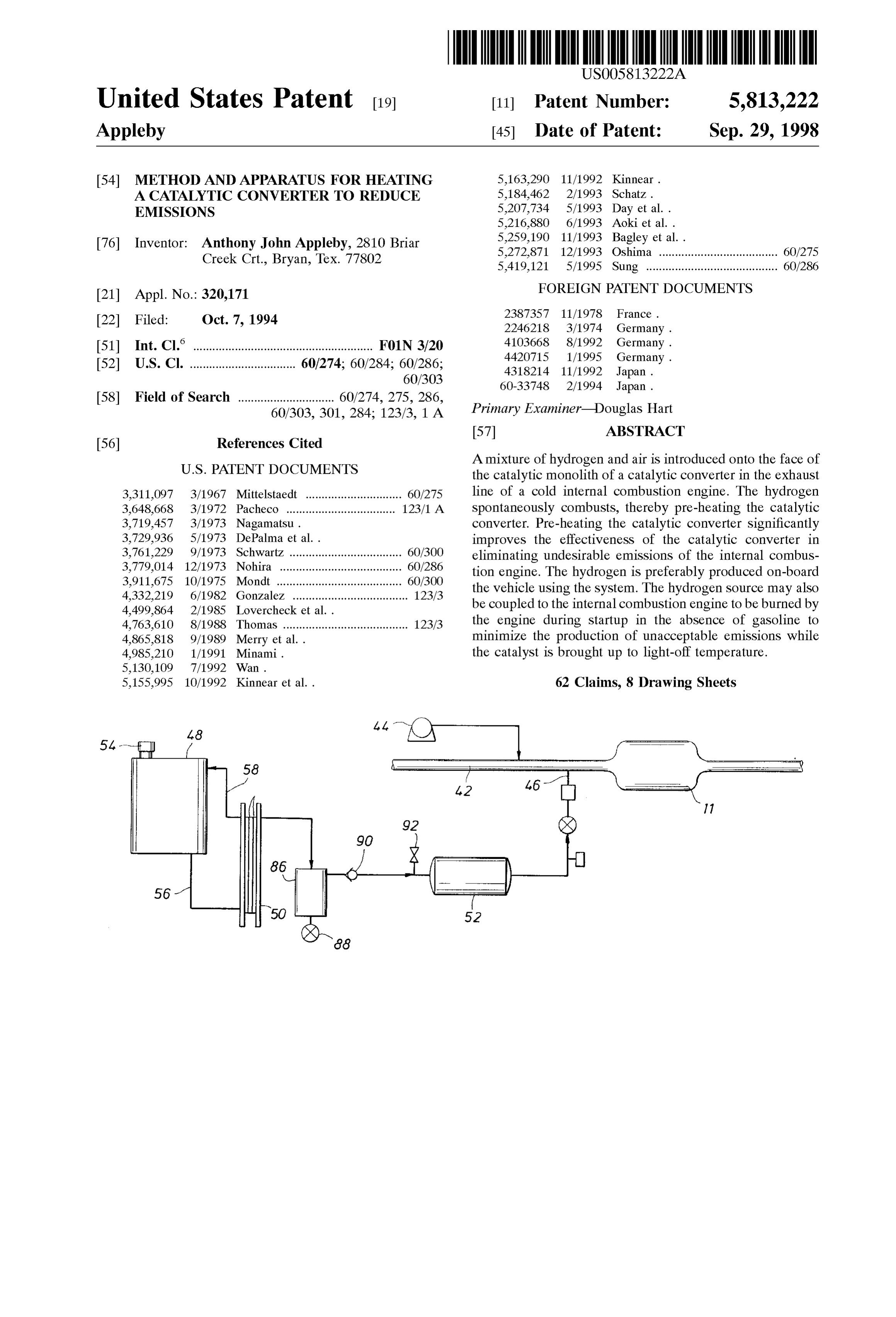
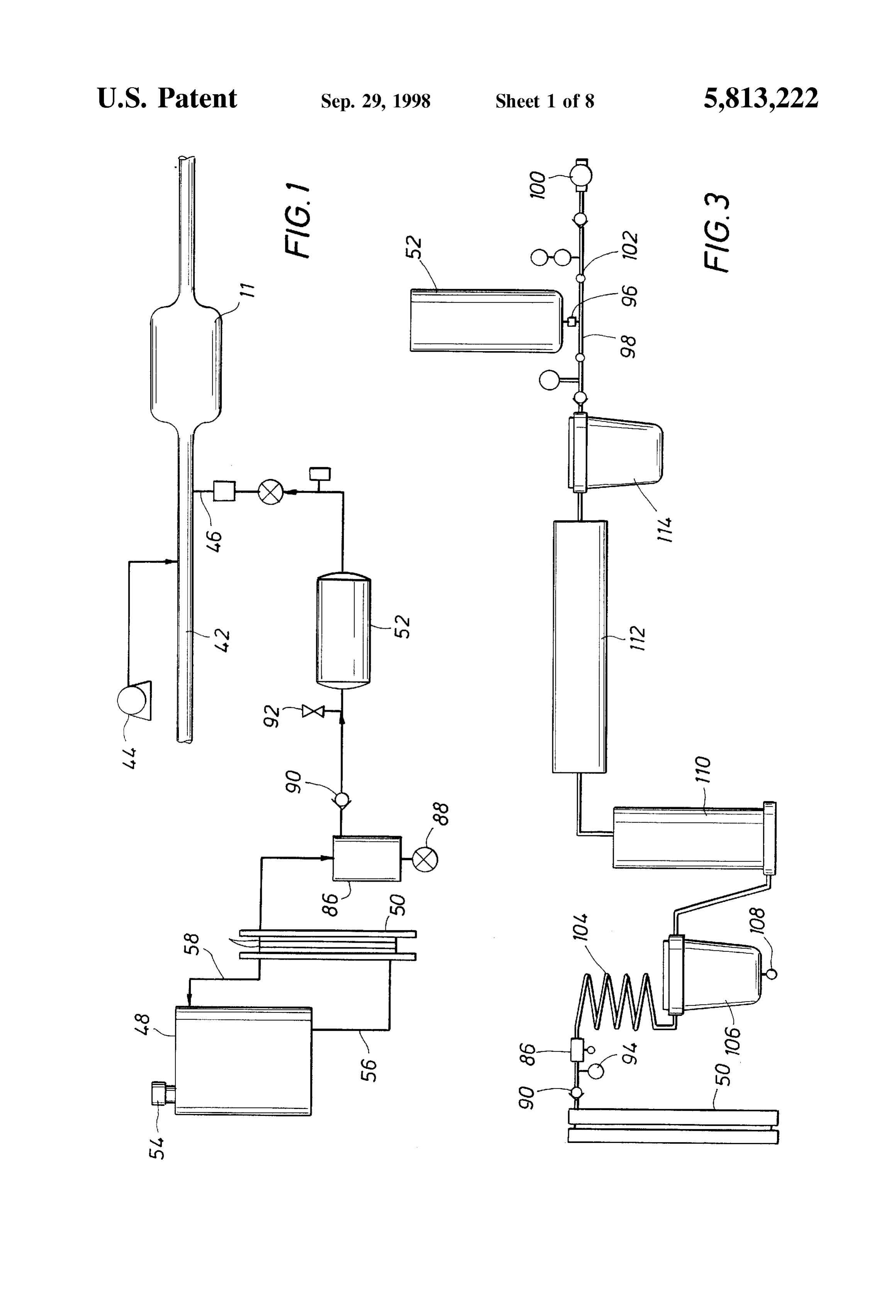
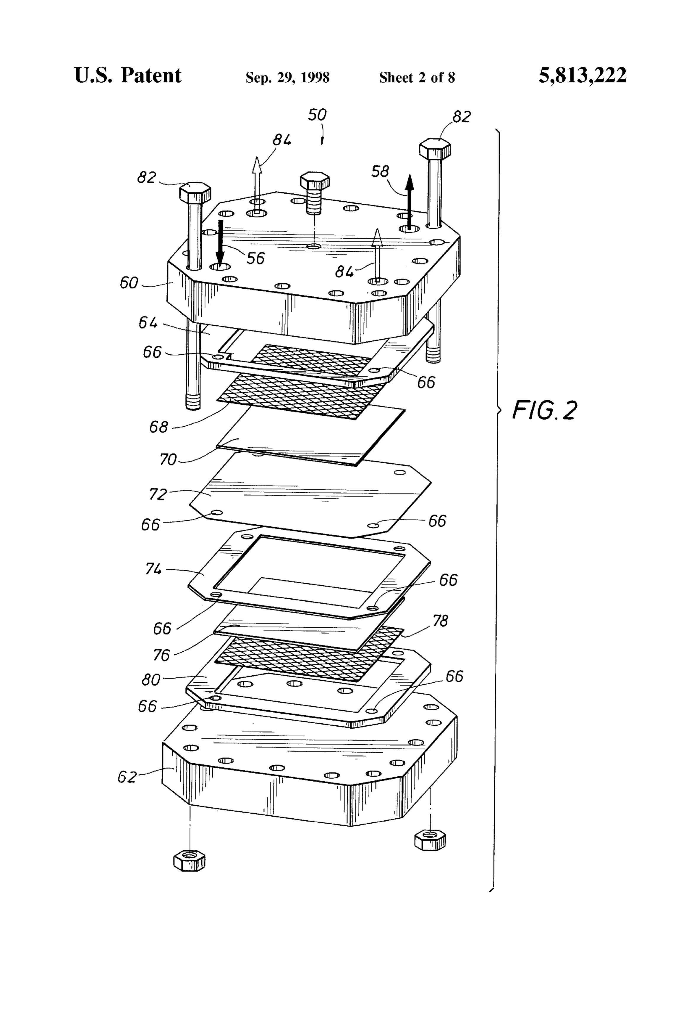
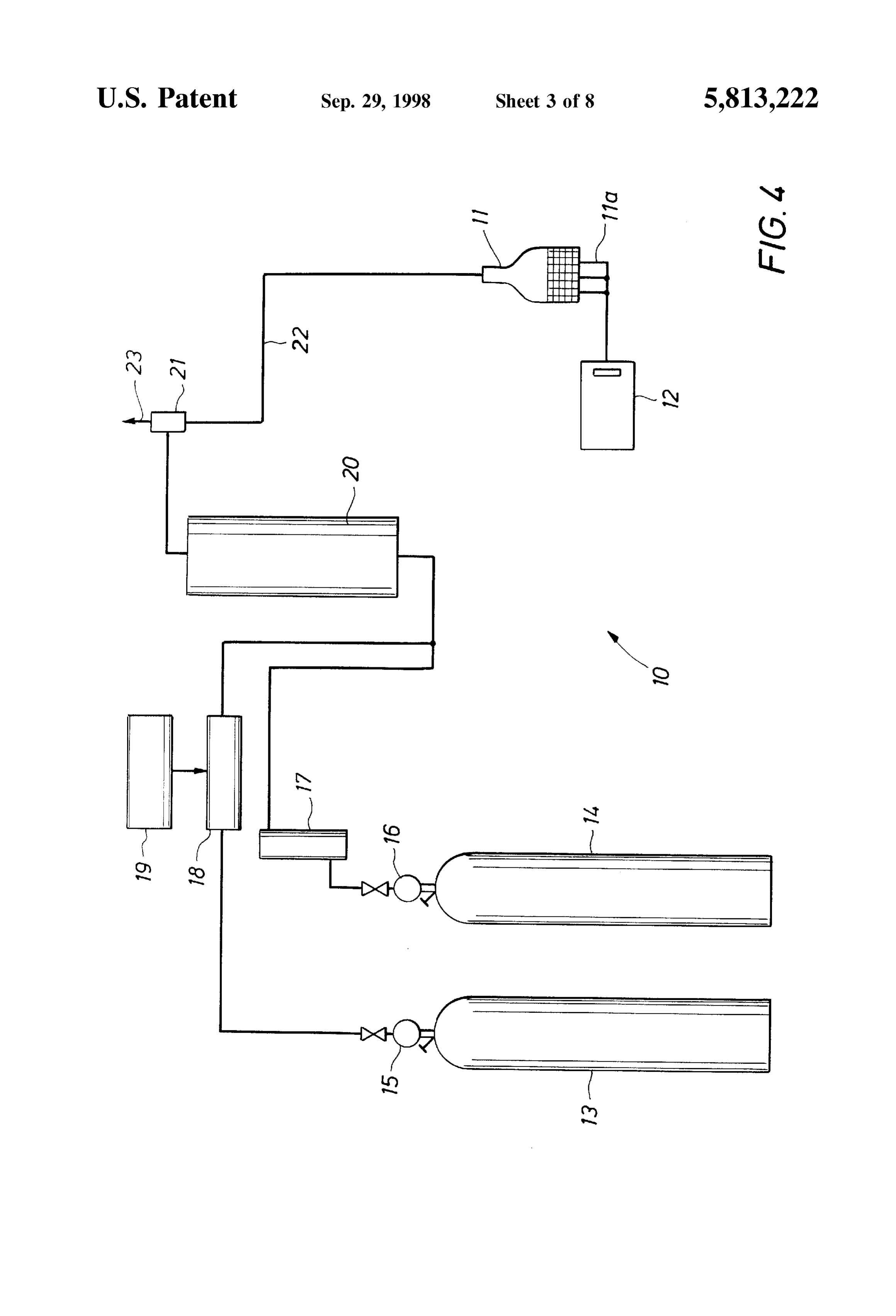
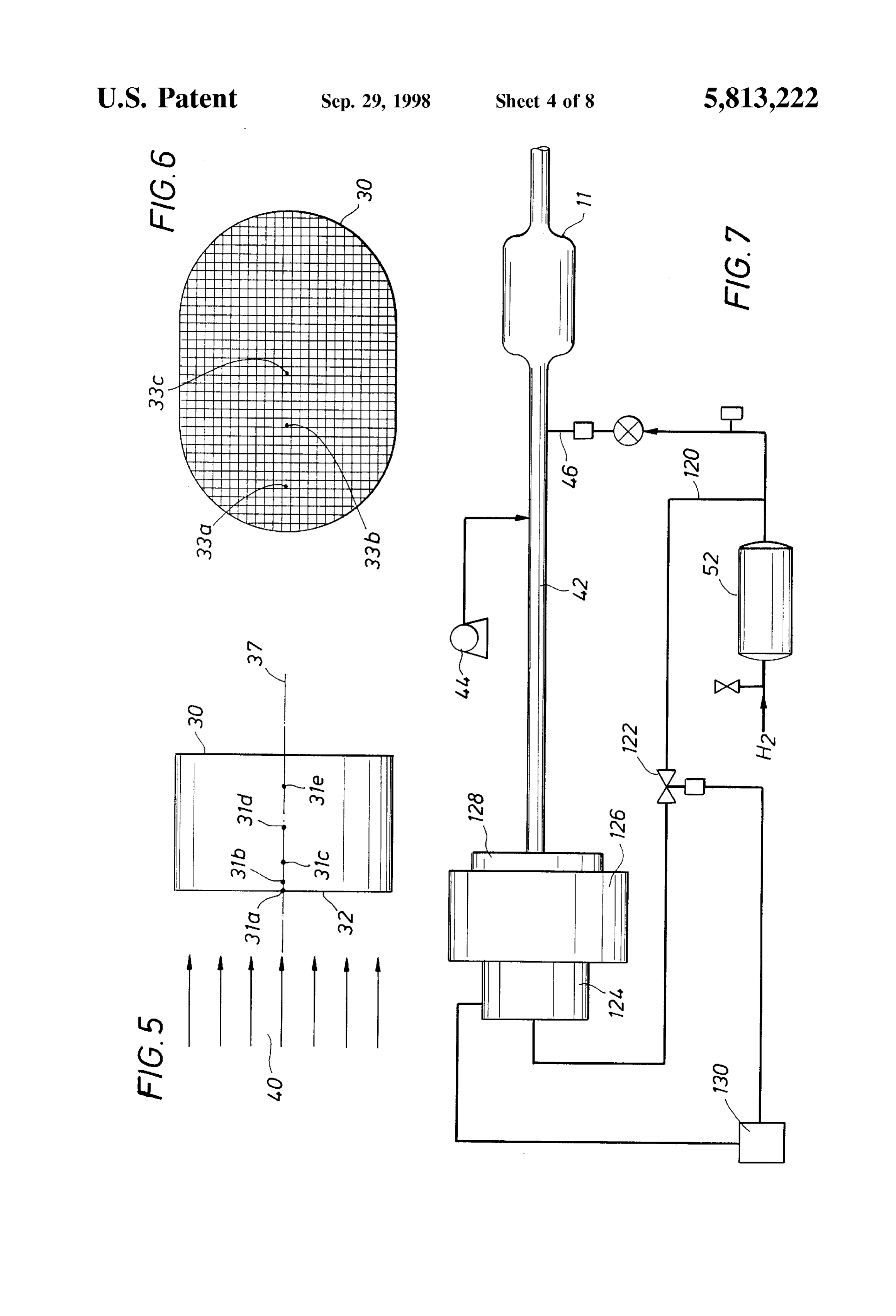
the cold Start condition and ignites the resulting Super-rich FIG. 1 is a Schematic diagram of the apparatus of the mixture to directly heat the catalyst. This approach has present invention for heating a catalytic converter; proved wholly unreliable and has other Serious drawbacks, FIG. 2 is an exploded view of a preferred electrolyzer that including reduced engine and catalyst life. may be employed in the present invention; To date, there has not been a catalytic converter heating 40 FIG. 3 is a Schematic of a hydrogen capturing and System which gives almost instantaneous heating of the handling detail of the System of the present invention; FIG. 4 is a Schematic of a test Setup to assist in the catalytic converter without the inherent drawbackS Stated determination above. of the ideal parameters of a System function Thus, there remains a need for an improved catalytic ing in accordance with the teachings of the present inven converter System that reduces ineffective catalytic action 45 tion; FIG. 5 is a sectional view of a simplified representation of immediately after cold Start-up of an engine. Such a System a catalytic converter monolith showing air and hydrogen must be simple and must not reduce the rated lifetime of the flow in the axial direction;
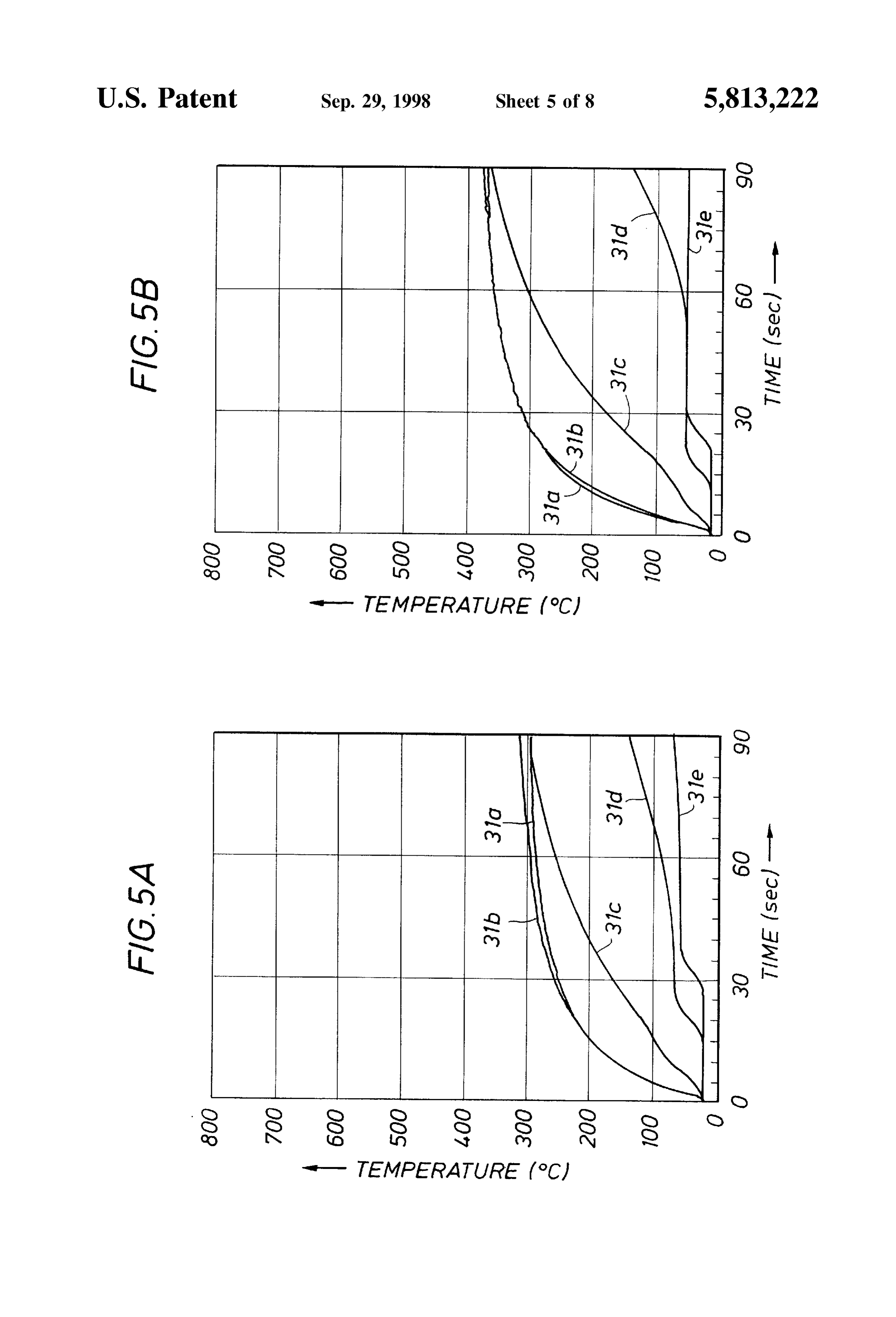
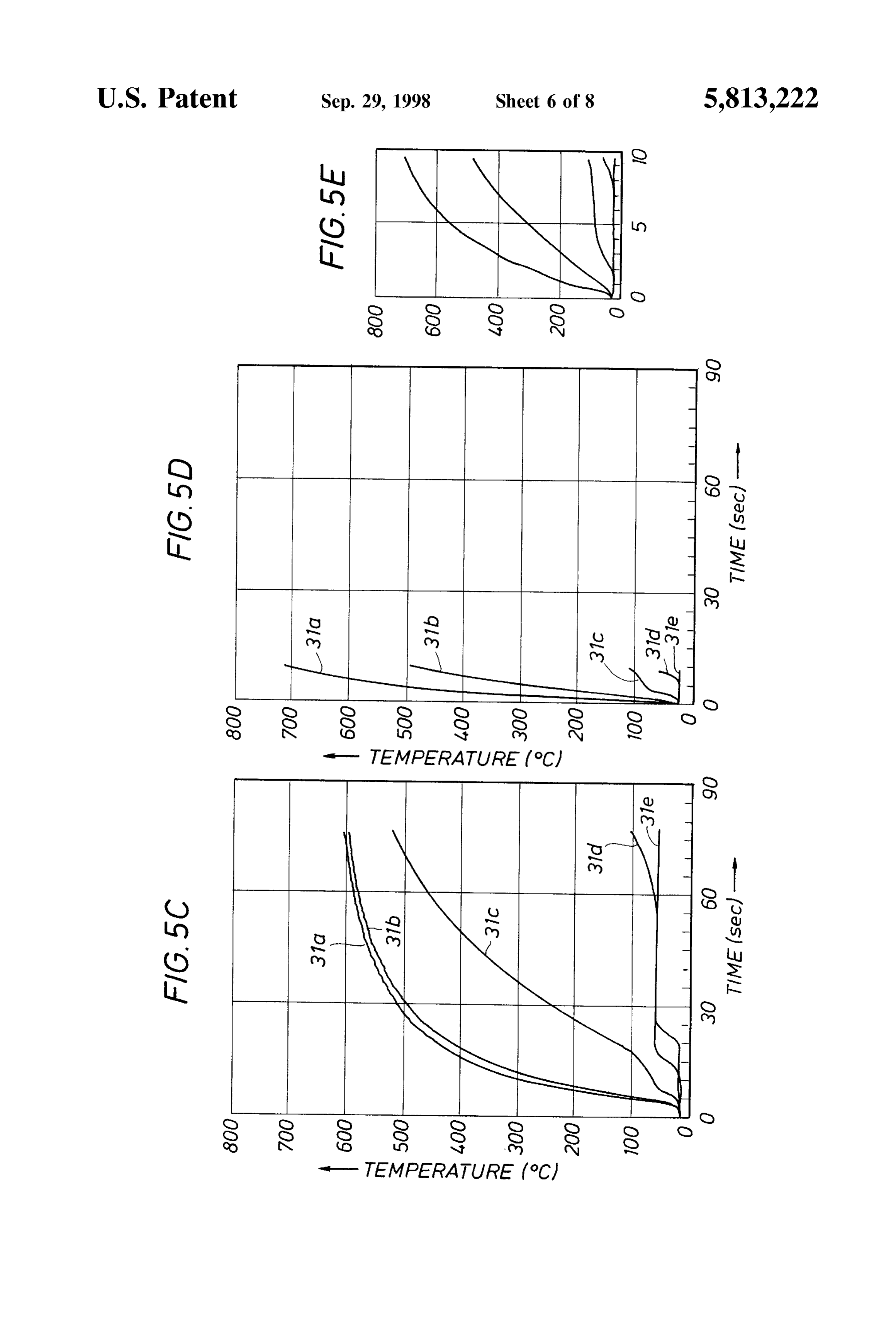
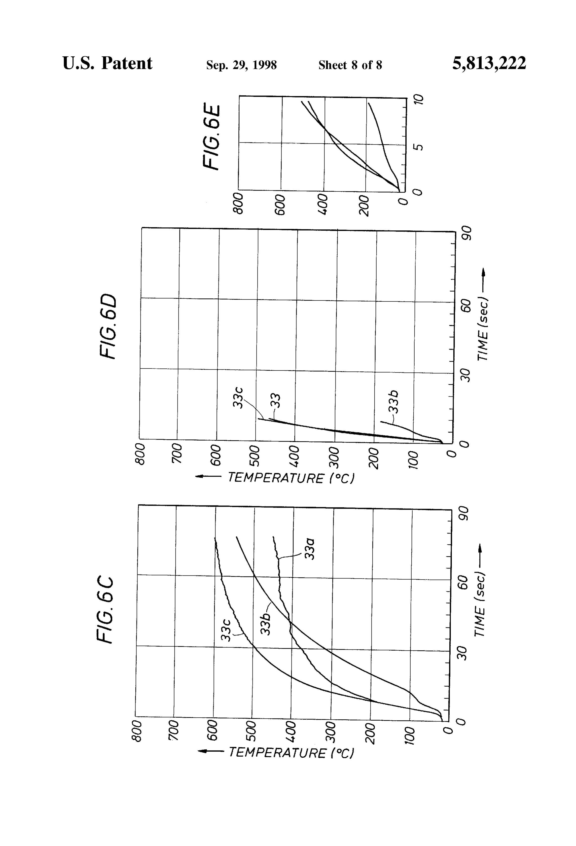
engine, the catalytic converter, or the battery components of FIGS.5A, 5B, 5C, 5D, and 5E are temperature plots of the the vehicle. variation of temperature with time along the axial length of 50 a catalytic converter monolith for different hydrogen con
SUMMARY OF THE INVENTION
centrations in a flowing gas Stream;
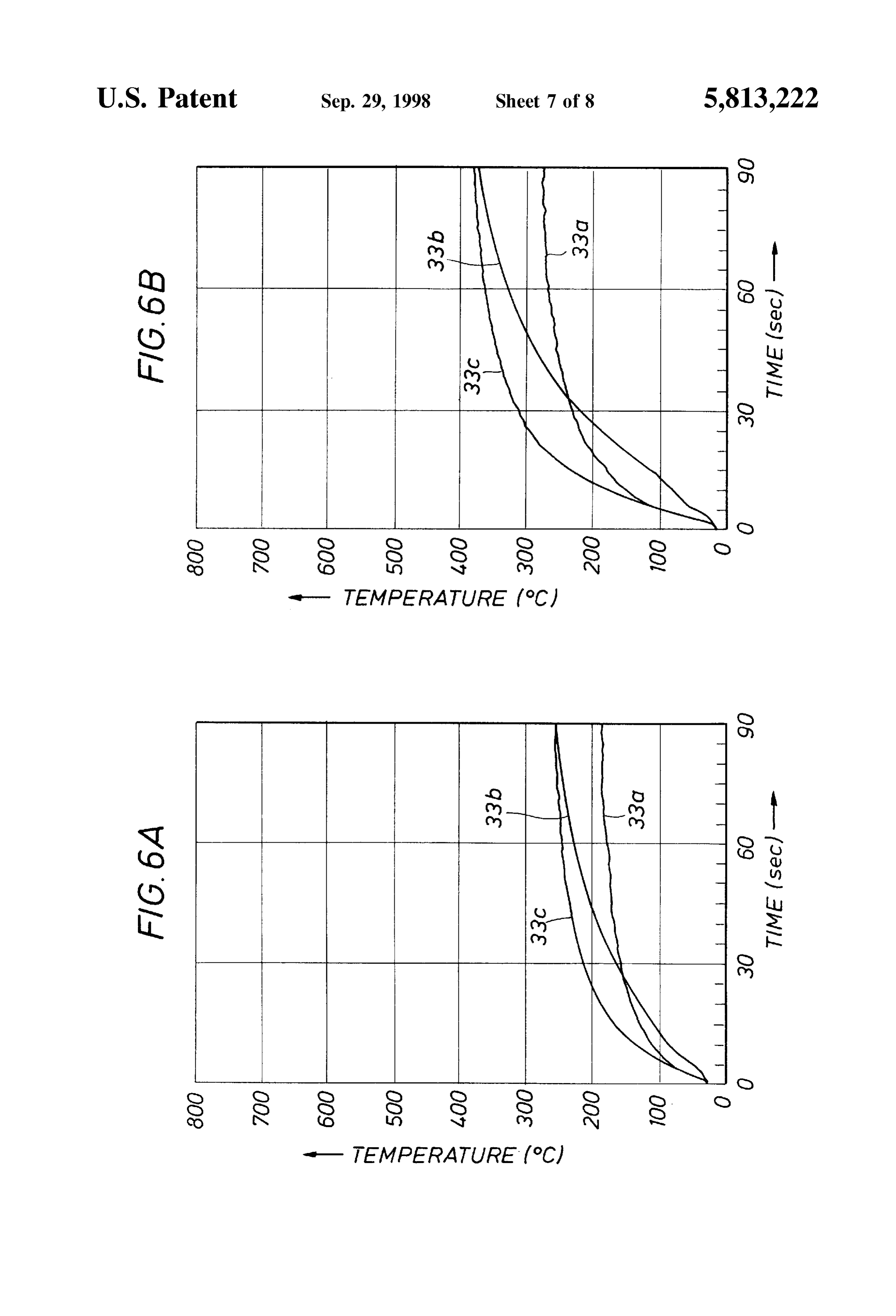
Accordingly, the present invention provides a method and FIG. 6 is a sectional view of a simplified representation of apparatus for reducing undesirable emissions from an inter a catalytic converter monolith for temperature measure nal combustion engine by using a gas that Spontaneously ments along the major radial direction in the monolith, combusts in the presence of a catalyst to heat the catalyst 55 FIGS. 6A, 6B, 6C, 6D, and 6E are temperature plots of the into its operating range in a minimal amount of time. In a variation of temperature with time along the major radial preferred embodiment, the catalyst is heated by providing a direction of a catalytic converter monolith for different controlled flow of hydrogen and a Source of oxygen, Such as hydrogen concentrations in a flowing gas Stream; and air, into the exhaust line or pipe, preferably at a point FIG. 7 is a Schematic diagram of the apparatus of the between the engine manifold and the catalytic converter. The 60 present invention depicting a System for the combustion of hydrogen combusts with the oxygen in the presence of the hydrogen for cold Startup assist for an internal combustion catalyst to produce water. This exothermic combustion pro engine.
vides localized heat at the catalyst which raises the tem perature of the catalyst material. DETAILED DESCRIPTION OF PREFERRED The hydrogen is preferably Supplied from an electrolyzer 65 EMBODIMENTS on board the vehicle which is supplied with DC power from The present invention provides a method and apparatus the vehicle's alternator via an AC/DC converter. Such an for thermally conditioning a catalyst in order to enhance the
Page 12
S 6 conversion of unacceptable emissions emanating from an injecting air into the exhaust line at Suitable pressure and internal combustion engine into water and other acceptable Volumetric flow rate to achieve the ideal air/hydrogen ratio emissions. mixture.
Referring first to FIG.4, the Schematic depicts the general The hydrogen source portion of the system of FIG. 1 configuration of a conditioning System 10 for catalytically provides another feature of the present invention. The major enhancing emission reactions. The System 10 includes a components of the System include a reservoir 48, an elec catalytic converter 11, a metered hydrogen Supply 13, and a trolyzer 50, and a hydrogen storage cylinder 52. As shown metered air Supply 14. Additionally, one or more thermo in FIG. 1, the electrolyzer 50 may preferably comprise a couples 11a are implanted at various positions along the plurality of stacked identical cells 51. The reservoir 48 radial and axial directions of the catalytic converter. The Serves both as a water reservoir and as a separator for thermocouples are connected to a data logger 12, capable of oxygen and water. In a preferred embodiment, the reservoir recording the temperature of the catalyst as a function of 48 may be a vehicle's windshield washer fluid storage time. The system 10 of FIG. 4 is particularly useful in container. A port 54 permits the introduction of water into demonstrating the efficacy of the present invention and for the reservoir and also serves as a vent to atmosphere for determining the optimum flow rates of hydrogen and air and 15 oxygen. Water flows by gravity drain or is pumped from the other System parameters. reservoir 48 to the electrolyzer 50 via a drain line 56. As the The flows of hydrogen and air from Supplies 13 and 14 are electrolyzer develops hydrogen and oxygen, the oxygen and controlled by valves or regulators 15 and 16, respectively. entrained water flows naturally back to the reservoir 48 via The regulator 16, which controls the air Supply, is preferably a return line 58.
coupled to a rotameter 17, which measures the air flow rate. The next major component of the hydrogen Source is the The metered air then flows to a mixing chamber 20. The flow electrolyzer 50, shown in greater detail in FIG. 2. In the of hydrogen, which is controlled through a valve or regulator following description of the electrolyzer 50, the materials of 15 and regulated by an electronically controlled mass flow construction referred to as "preferred” are the materials controller 18 in conjunction with the controller 19, is also 25 actually used in a test device to prove that the invention delivered to the mixing chamber 20. would work for its intended purpose. In commercial pro In the mixing chamber 20, the hydrogen and air are duction models of the present invention, where possible, leSS thoroughly mixed before passing through a three way valve expensive materials will be used throughout, Such as carbon 21. The three way valve 21 operates to provide a bypass of Steel for titanium where possible, and plastic Such as the hydrogen and air mixture directly to the Surrounding polypropylene where heat and StreSS will permit the use of environment via an outlet 23 or to a conduit 22, through Such material.
which the hydrogen and air mixture are introduced into the The electrolyzer 50 may be referred to herein as a proton catalytic converter 11. This configuration allows for a widely exchange membrane (PEM) electrolyzer 50. The proton varying flow of hydrogen and air to a catalytic converter to eXchange membrane itself may prove corrosive in this determine the proper hydrogen/air ratioS for practicing the 35 environment in contact with certain Substances, thus requir present invention. ing the careful Selection of the materials of construction of FIG. 5 depicts a catalytic converter monolith 30 in the the electrolyzer. For example, the PEM should only contact catalytic converter 11 that may be conditioned with the carbon or graphite. However, those of skill in the art will present invention. ArrowS 40 represent the Stream of air and readily recognize where leSS exotic materials than those hydrogen passing through conduit 22 and into contact with 40 listed in the following discussion that are located away from the monolith 30 along a central axis 37. Points 31a, 31b,31c, the PEM material itself and the oxygen electrode catalyst 31d, and 31e represent the location of thermocouple probes, can be readily employed without penalty. For example, as generally represented by 11a in FIG. 4, for the measure graphite will be the material of choice in certain Structural ment of temperatures along the axial or flow direction into elements, and not Some obvious candidates Such as copper, the catalytic converter. 45 aluminum, or iron, which can corrode thus forming ions that FIG. 6 depicts the radial distribution of a plurality of can poison the oxygen and/or hydrogen electrode catalysts. probes. 33a, 33b, and 33c within the monolith 30. Below are The PEM electrolyzer 50, formed as a stack as shown in listed Some results for variously changing parameters as FIG. 2, includes a pair of endplates 60 and 62. The endplates determined by the distribution of the thermocouple probes 60 and 62 are preferably titanium and measure 4.2"x4.2"x 31a–31e and 33a–33c. 50 %". Adjacent the top endplate 60 is an anodic cell frame 64. FIGS. 5A-D, inclusive, depict test results of the distri The cell frame 64 is preferably a carbon fiber-filled Teflon bution of temperatures detected by the thermocouples dis sheet, sold under the trademark Zymaxx by Du Pont. The tributed as shown in FIG. 5 for varying concentrations of cell frame 64 retains a 1:1 molar ratio of iridium and hydrogen. Similarly, FIGS. 6A-D, inclusive, depict test ruthenium dioxides (IrO2/RuO2) as the anodic electrocata results of the distribution of temperatures detected by the 55 lyst. The cell frame 64 also includes a plurality of flow ports thermocouples distributed as shown in FIG. 6 for the same 66 to permit the Supply of reactant (water) and/or removal of concentrations of hydrogen. These plots clearly show the electrolysis products (hydrogen or oxygen gases). Below the effectiveness of the heating on the face of the catalytic cell frame 64 is an expanded titanium metal current collector converter monolith and will assist those of skill in the art in (flow field) 68, preferably 25 Ti40-%2 from Exmet Corp. An Selecting optimum fluid flow rates in a particular applica 60 anode substrate 70 is preferably a porous titanium plate tion. measuring 2.49"x2.49"x0.05". Below the anode substrate 70 FIG. 1 shows an overall system of the present invention. is a proton exchange membrane 72, cut from a sheet of In this System, the catalytic converter 11 is located in an Nafion 117 from Du Pont which serves as a solid electrolyte exhaust line 42 from a vehicle's exhaust manifold, as shown. material and which is 175 um thick. The exhaust line 42 is provided with air from an air pump 65 FIG. 2 depicts a gasket 74, one of perhaps Several 44 and hydrogen from a hydrogen inlet line 46. The air pump installed where required. Gaskets 74 are stamped from could be any Suitable air Source, Such as a receiver, for 0.033" thick fluorosilicone sheet (Viton) and from 0.005"
Page 13
thick unsintered PTFE sheet. The electrolyzer 50 further an inert gas, Such as nitrogen. For Safety reasons, all air is includes a cathode Substrate 76 like the anode Substrate 70 first removed from the System by attaching a nitrogen gas and an expanded titanium flow field 78 like the titanium flow feedline at a purge gas inlet 94 downstream of a check valve field 68. 90. During the purging operation, the hydrogen Storage Finally, the PEM electrolyzer 50 includes a cathodic cell cylinder or vessel 52, preferably made of a metal hydride, is frame 80 formed of polychlorotrifluoroethylene (PCTFE) detached at a quick disconnect 96. This operation effectively sheet, sold under the trademark KEL-F by Afton Plastics. seals both the vessel 52 and a gas line 98, to keep the purge The cathodic cell frame 80 retains a fuel cell gas diffusion gas out of the vessel 52. The remainder of the system is then purged from the purge gas inlet 94 through a back preSSure electrode containing high Surface area colloidal platinum, regulator 100.
Supported on platinum black, having a platinum loading of To charge the system with hydrogen, a needle valve 102 4.0 mg/cm as the cathodic electrocatalyst layer. between the Storage vessel 52 and the back preSSure regu As shown in FIG. 2, the various components of the PEM lator 100 is shut. Hydrogen gas generated by the electrolyzer electrolyzer are Stacked together and retained with a plural is processed through a four-stage process to remove ity of tie rods 82, preferably 16 Such tie rods. Stainless steel 15 entrained water (liquid or vapor) and any oxygen contami tubing, such as SS316, are then screwed into four threaded nant from the hydrogen Stream before Storage. The first Step ports on one of the titanium endplates. These ports are the involves removal of a Small amount of entrained liquid water inlet port 56, the oxygen outlet port 58, and a pair of water coming from the electrolyzer in the hydrogen gas. hydrogen outlet ports 84. To minimize electrical contact This entrained liquid water is removed without a preSSure resistances, the titanium endplates 60 and 62 and the loss by means of the entrained liquid water trap 86. The expanded titanium metal current collectors 68 and 78 may Second Step involves cooling the hydrogen gas Stream from be electroplated with a thin film of gold. the electrolyzer temperature to ambient in a condensing coil The cathode and the anode of the electrolyzer are of 104. The electrolyzer is typically at least 20° C. above Special construction. The cathodic electrode Structure for ambient, with the exact temperature depending on electro hydrogen evolution is fashioned from commercially avail 25 lyZer operating conditions. This Second step condenses a able fuel cell gas diffusion electrodes from E-TEK of Natick, Substantial portion of the water vapor in the hydrogen gas Mass. This structure comprises a hydrophobic gas diffusion Stream. This condensed water could absorb a significant layer on a carbon cloth backing, which acts as a Support for amount of alcohol, which may be present during operation the active hydrophilic electrocatalyst layer. This active layer using windshield washer fluid as the electrolyzer reactant contains high Surface area colloidal platinum (~100 m/g), feed. The condensate is collected in a condensate collector supported on carbon black (60 wt % Pt on C), yielding a 106 and removed through a drain valve 108. platinum loading of 4.0 mg/cm. The cathodic electrode At this point, the hydrogen gas Stream is still Saturated structure, having an area of 40 cm, was hot-pressed onto with water vapor, but now at a lower temperature. This one side of a segment of precleaned Nafion 117 PEM Saturated gas Stream is next passed into a Zeolite-filled gas material. Hot-pressing was carried out between the plates of 35 drier 110. This drier absorbs water vapor and any alcohol a hot-press, elevated to 200 C. for 60 seconds, and using a Vapor present when using a windshield washer fluid feed. force of 15,000 pounds. Any oxygen contaminant present in the hydrogen gas Stream For the anodic electrocatalyst layer, a 1:1 molar ratio of is then eliminated in a catalytic recombiner or oxygen iridium and ruthenium chlorides are dissolved in ca. 8 ml of eliminator 112 to reduce it to water. Final clean-up of the concentrated HCl and heated to almost dryness. The result 40 hydrogen gas Stream is accomplished in a Second Zeolite ing chlorides are then dissolved in isopropanol to make an absorber bed in a polishing drier 114. The polishing drier ink-like coating. A porous titanium plate, 0.05" thick, of removes traces of water produced by the catalytic recom about 50% porosity, made from sintered titanium spheres of biner 112.
about 0.005" in diameter from Astro Met of Cincinnati, The hydrogen gas handling System of FIG. 3 is designed Ohio, is etched in 12% HBF for 60 seconds and rinsed with 45 for relatively short term operation; longer term operations, isopropanol. This Substrate is then coated with the ink-like for example 100,000 miles, would utilize other methods of mixture and the Solvent evaporated under low heat of about water removal known in the art. A Satisfactory metal hydride 90° C. The coating and drying procedure is repeated Seven hydrogen Storage unit is available from Hydrogen Consult times, then the electrode is heated in a furnace at 400° C. for ants of Littleton, Colo. Such an available unit can store 30 10 minutes in ambient air. The coating, drying and furnace 50 liters of hydrogen, which can be delivered at 30-45 psig, treatment is repeated twice more, but with a final baking with recharging using hydrogen gas at 100-200 psig. time of two hours instead of 10 minutes. As previously described, it has been found that the Returning to FIG. 1, in addition to the reservoir 48 and the introduction of a relatively Small percentage of hydrogen in electrolyzer 50, the System includes a hydrogen Storage the air Stream of a typical automobile gas exhaust provides cylinder and various Supporting components. These compo 55 nearly Spontaneous heating of a major portion of a face 32 nents include a liquid water trap 86 to eliminate most of the (FIG. 5) of the catalyst material almost immediately follow entrained water from the hydrogen from the electrolyzer, a ing ignition in the internal combustion engine providing the Solenoid valve 88 to blow out the trap, a check valve 90, and exhaust gas. This heating along the face 32 of the converter a pressure relief valve 92 to protect the System against is fortuitous because it has been found that the most effective overpreSSurization. FIG. 3 depicts additional details and a 60 Site for providing local heating is along and near the preferred arrangement of the hydrogen gas handling and upstream face 32 of the catalyst monolith 30. In fact, where capture System. the monolith 30 is made of a material that heats slowly when As previously described, the electrolyzer 50 includes a used in association with the present invention, the face 32 proton exchange membrane in its Stacked construction So may comprise a more reactive catalytic material to bring the that generated oxygen is vented to the water Source reservoir 65 entire catalytic converter to light-off more quickly. and the hydrogen generated can be accumulated at pressure. In addition, the heat Supplied by the Spontaneous com Prior to operation, the system of FIG.3 permits purging with bustion of the hydrogen in the presence of the catalytic
Page 14
converter 30 produces only a Small quantity of water as a The principles, preferred embodiment, and mode of product of the reaction, which does not degrade the perfor operation of the present invention have been described in the mance of the catalytic converter. foregoing Specification. This invention is not to be construed A system 10 built in accordance with the present inven as limited to the particular forms disclosed, Since these are tion as depicted in FIGS. 4, 5, and 6 have provided preferred regarded as illustrative rather than restrictive. Moreover, parameters of air and hydrogen flow. The air flow rate, variations and changes may be made by those skilled in the depending on engine Size and tuning parameters, typically art without departing from the Spirit of the invention. falls in the range of 40 to 250 liters per minute (pm). The I claim:
ideal range is between 80 and 200 lpm, depending on engine 1. A method of heating a catalyst from a cold condition to size. Effective concentrations of hydrogen for these flow light-off temperature for carbon-containing compounds, the rates are one to twenty-eight Volume percent, with a pre method comprising the Steps of introducing gaseous hydro ferred range of five to eighteen percent. The ideal range of gen and oxygen to the catalyst to induce Spontaneous hydrogen concentration, again depending on engine size, has been found to be eight to fifteen percent. For example, at 150 exothermic the catalyst combination of the hydrogen and the oxygen by prior to the introduction of reactive organic lpm flow rate acroSS the catalytic converter, the ideal range 15 gases or carbon monoxide to the catalyst. for hydrogen concentration in that flow is 12 to 13 volume 2. The method of claim 1 further comprising the step of percent. Under those conditions, light-off temperature at the Storing gaseous hydrogen within a hydrogen Storage vessel face 32 is reached in about one second. At 90 lpm and at 8.5 prior to the Step of introducing hydrogen. to 11 Volume percent hydrogen, light-off is achieved in about 3. The method of claim 2 further comprising the step of two Seconds.
The power consumption at the catalyst varies depending Step of Storingwater electrolyzing to produce hydrogen to be Stored in the hydrogen.
on the flow rate and the concentration of hydrogen. For 4. The method of claim 3 further comprising the step of example, at a flow rate of thirty to fifty lpm and a concen purifying the hydrogen produced in the Step of electrolyzing tration of 10–11%. Volume percent hydrogen, the power by removing water and other impurities from the hydrogen. required to heat the monolith to light-off is approximately 25 5. The method of claim 1 wherein the source of oxygen 1.5 watt hours. Similar results in an EHC unit require comprises air.
approximately 10 to 15 watt hours. 6. The method of claim 3 wherein the step of electrolyzing The present invention is also suitable for use in low is carried out on-board a vehicle driven by an internal ambient temperature conditions, as low as -7°C. or lower. combustion engine.
Depending on the active catalyst compositions used, the 7. The method of claim 6 further comprising the step of amount of time required to achieve light-off may double. In providing electrical power for the Step of electrolyzing from those conditions, it may be desirable to add a Small electrical an AC to DC converter that is powered from an alternator heater, which would be much smaller than an EHC heater driven by the engine.
and require only about 200 watts of power, in order to 8. An apparatus for conditioning a catalyst within a achieve the results at normal ambient temperatures. 35 catalytic converter from a cold Start condition, the apparatus Finally, FIG. 7 depicts an on-board hydrogen ignition comprising:
assist System of the present invention. A Source of hydrogen, a. a conditioning agent Storage container for Storing a Such as an electrolyzer as before or any Suitable means, fills quantity of a conditioning agent; the hydrogen Storage cylinder 52. An ignition Supply line b. a conduit coupling the conditioning agent Storage 120 taps off the hydrogen line to a control valve 122. The 40 container to the catalytic converter; and control valve 122 controls the Supply of hydrogen into an c. means for introducing the conditioning agent to the engine ignition 124. The engine ignition 124 includes the fuel, air, and electrical components for an internal combus catalytic converter prior to the introduction of reactive tion engine 126. Thus, the hydrogen can be Supplied at any organic gases or carbon monoxide to the catalytic convenient location So that it is injected into the cylinders of 45 converter until the catalytic converter reaches lightoff the engine 126. For example, hydrogen under pressure can temperature for carbon-containing compounds and, be Supplied to the intake manifold where there is already a once the catalytic converter has reached lightoff fuel/air mixture (during the inlet cycle), or the hydrogen can temperature, Stopping the introduction of the condition be mixed with air before it goes into the engines fuel ing agent to the catalytic converter, only at about the injection System, or other means. 50 lightoff temperature of the catalytic converter.
The preferred system of FIG. 7 turns the internal com 9. A system for the reduction of the cold-start emissions bustion engine 126 into a hydrogen fuel injected engine for from an internal combustion engine with an exhaust line and the first few Seconds of Start-up, before any gasoline is a catalytic converter in the exhaust line comprising: introduced into the engine. This way, the catalytic converter a. hydrogen Storage container for Storing a quantity of can be brought to light-off while the engine is producing no 55 hydrogen;
undesirable emissions. Then, when gasoline is finally b. a fluid flow path coupling the hydrogen Storage con injected into the System, the catalytic converter is heated to tainer to the exhaust line; and efficient operating temperature. c. a control valve in the fluid flow path to direct hydrogen Expended fuel gases are collected in an output manifold into the catalytic converter prior to the introduction of 128 and flow into the exhaust line 42. An ignition control 60 reactive organic gases or carbon monoxide to the 130 provides control signals to the control valve 122 for the catalytic converter until the catalytic converter reaches introduction of hydrogen and to the engine ignition 124 to lightoff temperature for carbon-containing compounds coordinate hydrogen introduction during cold Start opera and, once the catalytic converter has reached lightoff tions. The on-board hydrogen ignition assist System func temperature, to Stop the introduction of the condition tions with or without the catalyst conditioning System but is 65 ing agent to the catalytic converter. preferably included with Such a System Since they may both 10. The system of claim 9 further comprising: use the hydrogen generation and on-board Storage. a. a Source of water;
Page 15
b. a electrolyzer coupled to the Source of water to elec 21. The system of claim 9 further comprising a catalytic trolytically produce hydrogen; and converter including:
c. a fluid flow path to direct hydrogen produced in the a. a monolith of a first catalytic material, the monolith electrolyzer into the hydrogen Storage container. having an inlet face, and 11. The system of claim 10 further comprising a hydrogen b. a layer on the inlet face, the layer made of a Second purifier in the fluid flow path. catalytic material that heats more rapidly in the pres 12. The system of claim 11 wherein the hydrogen purifier ence of hydrogen and oxygen than the first catalytic comprises a water trap to remove water entrained with the material.
hydrogen and an oxygen eliminator to remove oxygen 22. The system of claim 19 further comprising a catalytic contaminant that may be present with the hydrogen. converter including:
13. The system of claim 9 further comprising a source of a. a monolith of a first catalytic material, the monolith air connected to the exhaust line. having an inlet face, and 14. The system of claim 10 further comprising an alter b. a layer on the inlet face, the layer made of a Second nator driven by the internal combustion engine to develop catalytic material that heats more rapidly in the pres AC power and an AC/DC converter electrically coupled to 15 ence of hydrogen and oxygen than the first catalytic material.
the alternator to provide DC power to the electrolyzer. 23. The system of claim 10 wherein the source of water 15. An auxiliary System for an internal combustion engine comprises a vehicle's windshield-washer fluid reservoir. having a fuel and air intake, combustion chambers, and an 24. The system of claim 21 wherein the electrolyzer exhaust, the exhaust including a catalytic converter, the comprises a plurality of cells.
auxiliary System comprising: 25. The system of claim 22 wherein the electrolyzer a. a hydrogen Storage container; comprises a plurality of cells.
b. a control valve between the hydrogen Storage container 26. A method of heating a catalyst in the exhaust System and the engine to Selectively provide hydrogen to the of an internal combustion engine from a cold condition to light-off temperature for carbon-containing compounds engine when the control valve is open; and 25 comprising the Steps of introducing gaseous hydrogen and c. an internal combustion engine ignition control coupled oxygen to the catalyst to induce Spontaneous exothermic to the control valve to open the control valve for a combination of the hydrogen and the oxygen by the catalyst predetermined period of time during the Startup of the during Startup of the internal combustion engine. engine So that the engine is started with hydrogen until 27. The method of claim 26 further comprising the step of the catalytic converter reaches lightoff temperature for Storing gaseous hydrogen within a hydrogen Storage vessel carbon-containing compounds before the introduction prior to the Step of introducing hydrogen.
of a hydrocarbon or oxygenated hydrocarbon fuel to the 28. The method of claim 26 further comprising the step of engine. Storing hydrogen as a metal hydride using a hydriding alloy 16. The system of claim 15 wherein the control valve is in the hydrogen Storage vessel.
in fluid communication with the intake of the engine. 35 29. The method of claim 27 further comprising the step of 17. The system of claim 15 wherein the control valve is electrolyzing water to produce hydrogen to be Stored in the in fluid communication with the cylinders of the engine. Step of Storing hydrogen.
18. The system of claim 15 further comprising an elec 30. The method of claim 26 further comprising the step of trolyzer connected to the hydrogen Storage container for the Storing gaseous Oxygen Within an OXygen Storage Vessel production of hydrogen to charge the hydrogen Storage 40 prior to the Step of introducing oxygen. container. 31. The method of claim 30 further comprising the step of 19. A system for the reduction of the cold-start emissions electrolyzing water to produce oxygen to be stored in the from an internal combustion engine with an exhaust line and Step of Storing Oxygen.
a catalytic converter in the exhaust line, the engine further 32. The method of claim 29 further comprising the step of having a fuel and air intake and combustion chambers, the 45 purifying the hydrogen produced in the Step of electrolyzing System comprising: by removing water and other impurities from the hydrogen. a. hydrogen Storage container, 33. The method of claim 26 wherein the source of oxygen b. a fluid flow path coupling the hydrogen Storage con comprises air.
tainer to the exhaust line to direct hydrogen into the 34. The method of claim 26 wherein the source of oxygen catalytic converter; 50 comprises oxygen produced by electrolysis on-board a
. a Source of oxygen connected to the exhaust line; and vehicle. 35. The method of claim 29 wherein the step of electro d. a controllable port from the hydrogen Storage container lyzing is carried out on-board a vehicle driven by an internal to the engine wherein hydrogen from the Storage con combustion engine.
tainer is ported to the engine for a controlled period of 55 36. The method time during Start-up of the engine So that the engine is providing electricalofpower claim 35 further comprising the step of for the Step of electrolyzing from
Started with hydrogen until the catalytic converter an AC to DC converter that is powered from an alternator reaches lightoff temperature for carbon-containing driven by the engine.
compounds beforc the introduction of a hydrocarbon or 37. A method of heating a catalyst in the exhaust System oxygenated hydrocarbon fuel to the engine. 60 of an internal combustion engine from a cold condition to 20. The method of claim 1 wherein the catalyst comprises light-off temperature for carbon-containing compounds a. a monolith of a first catalytic material, the monolith comprising the Steps of introducing gaseous hydrogen and having an inlet face, and oxygen to the Surface of the catalyst to induce Spontaneous b. a layer on the inlet face, the layer made of a Second exothermic combination of the hydrogen and the oxygen by catalytic material that heats more rapidly in the pres 65 the catalyst after Startup of the internal combustion engine. ence of hydrogen and oxygen than the first catalytic 38. The method of claim 37 wherein the catalyst contains material. platinum or palladium.
Page 16
39. The method of claim 37 further comprising the step of c. a control valve in the oxygen flow path for introducing Storing gaseous hydrogen within a hydrogen Storage vessel Oxygen from the oxygen Storage container to the cata prior to the Step of introducing hydrogen. lytic converter simultaneously with the introduction of 40. The method of claim 39 further comprising the step of hydrogen to the catalytic converter. electrolyzing water to produce hydrogen to be Stored in the 5 50. The method of claim 3 wherein the step of electro Step of Storing hydrogen. lyzing water produces electrochemically compressed hydro 41. The method of claim 40 further comprising the step of gen by the electrolyzer.
purifying the hydrogen produced in the Step of electrolyzing 51. The method of claim 1 further comprising the step of by removing water and other impurities from the hydrogen. Storing gaseous Oxygen Within an OXygen Storage Vessel 42. The method of claim 37 wherein the source of oxygen prior to the Step of introducing oxygen.
comprises air. 52. The method of claim 51 further comprising the step of 43. The method of claim 37 wherein the source of oxygen electrolyzing water to produce oxygen to be stored in the comprises oxygen produced by electrolysis on-board a Step of Storing Oxygen.
vehicle. 53. The method of claim 52 further comprising the step of 44. The method of claim 40 wherein the step of electro 15 purifying the oxygen produced in the Step of electrolyzing lyzing is carried out on-board a vehicle driven by an internal by removing water and other impurities from the Oxygen. combustion engine. 54. The method of claim 52 wherein the step of electro 45. The method of claim 44 further comprising the step of lyzing water produces electrochemically compressed oxy providing electrical power for the Step of electrolyzing from gen by the electrolyzer.
an AC to DC converter that is powered from an alternator 55. The method of claim 1 further comprising the step of driven by the engine. 20 storing oxygen for introduction in the Step of introducing 46. An apparatus for conditioning a catalyst within a OXygen.
catalytic converter in the exhaust System of an internal 56. A system for the reduction of the cold-start emissions combustion engine from a cold Start condition, the apparatus from an internal combustion engine with an exhaust line and comprising: a catalytic converter in the exhaust line comprising, a. a hydrogen Storage container for Storing a quantity of 25 (a) a hydrogen storage container for storing a quantity of a hydrogen; hydrogen;
b. a conduit coupling the hydrogen Storage container to (b) an oxygen storage container for storing a quantity of the catalytic converter; and OXygen, c. means for introducing the hydrogen to the catalytic (c) a first fluid flow path coupling the hydrogen Storage converter during Startup of the internal combustion 3O container to the exhaust line to direct hydrogen into the engine until the catalytic converter reaches and main catalytic converter prior to the introduction of reactive tains lightoff temperature for carbon-containing com organic gases or carbon monoxide to the catalytic pounds. converter until the catalytic converter reaches lightoff 47. An apparatus for conditioning a catalyst within a temperature for carbon-containing compounds, and catalytic converter in the exhaust System of an internal 35 (d) a second fluid flow path coupling the oxygen storage combustion engine from a cold Start condition, the apparatus container to the exhaust line to direct oxygen into the comprising: catalytic converter with the hydrogen of Step c. a. a hydrogen Storage container for Storing a quantity of 57. The system of claim 56 further comprising: a hydrogen;
b. a conduit coupling the hydrogen Storage container to 40 a. a Source of water;
the catalytic converter; and b. a electrolyzer coupled to the Source of water to elec c. means for introducing the hydrogen to the catalytic trolytically produce hydrogen and oxygen; converter after Startup of the internal combustion c. a hydrogen Storage container to Store the hydrogen engine until the catalytic converter reaches and main produced by the electrolyzer, tains lightoff temperature for carbon-containing com 45 d. an oxygen Storage container to Store the oxygen pro pound. duced by the electrolyzer;
48. An auxiliary System for an internal combustion engine e. means for directing the hydrogen from the hydrogen having a fuel and air intake, combustion chambers, and an Storage container and the oxygen from the oxygen exhaust line, the exhaust including a catalytic converter, the Storage container into the exhaust line. auxiliary System comprising: 58. The system of claim 57 further comprising an oxygen a. a hydrogen Storage container; 50 purifier coupled to the oxygen Storage container.
b. a first control valve between the hydrogen Storage 59. The system of claim 58 wherein the oxygen purifier container and the engine to Selectively provide hydro comprises a water trap to remove water entrained with the gen to the engine when the control valve is open; OXygen.
c. a Second control valve between the hydrogen Storage 55 60. The system of claim 15 further comprising: container and the exhaust; a. an OXygen Storage container;
d. an internal combustion engine ignition control coupled b. an electrolyzer connected to the hydrogen Storage to the second control valve to open the control valve for container and the oxygen Storage container for the a predetermined period of time during the Startup of the production of hydrogen to charge the hydrogen Storage engine So that the engine is started with hydrogen; and container and OXygen to charge the OXygen Storage e. a hydrogen control for introducing the conditioning 60 container.
agent to the catalytic converter until the catalytic con 61. The system of claim 22 wherein at least one of said Verter reaches lightoff temperature for carbon first and Second catalytic materials includes platinum or containing compounds. palladium.
49. The system of claim 48 further comprising: 62. The system of claim 10 wherein the source of water a. an OXygen Storage container, 65 contains an antifreeze fluid in which water is miscible. b. an oxygen flow path coupling the oxygen Storage container to the catalytic converter; and
Provenance
- Collection
- Cited prior art
- Original PDF
- patentimages.storage.googleapis.com →
- Filed
- 1994-10-07
- Pages
- 16
- Method
- pdftotext (the PDF's own text layer) + pdftoppm 300dpi page scans
- Source
- Google Patents bibliographic record
- Granted
- 1998-09-29
- Inventors
- Anthony John Appleby
- Transcribed from
- patentimages.storage.googleapis.com →