patent · US6235254
Hybrid catalyst heating system with water removal for enhanced emissions control
22 May 2001
Page 1 — bibliographic record
(12) United States Patent (10) Patent No.: US 6,235,254 B1 Murphy et al. (45) Date of Patent: *May 22, 2001
(54) HYBRID CATALYST HEATING SYSTEM 5,259,190 11/1993 Bagley et al. ......................... 60/300 WITH WATER REMOVAL FOR ENHANCED 5,357,752 * 10/1994 Lucchesi ..... ... 60/274 EMISSIONS CONTROL 5,379.592 1/1995 Waschkuttis ... 60/286 5,419,121 5/1995 Sung et al. ....... ... 60/274 (75) Inventors: Oliver J. Murphy; Rajesh T. Kukreja, both of Bryan, TX (US)
s 5,498,278 3/1996 Edlund ..................................... 96/11 5.569.441 10/1996 Engler .................................... 60/300 (73) Assignee: Lynntech, Inc., College Station, TX 2- Y/ -- a f ngler f (US) (List continued on next page.) (*) Notice: This patent issued on a continued pros- FOREIGN PATENT DOCUMENTS ecution application filed under 37 CFR 4103668A1 2/1991 (DE).
1.53(d), and is subject to the twenty year patent term provisions of 35 U.S.C. OTHER PUBLICATIONS 154(a)(2). P. Mark Golben, John E. Fox, PCT Patent Application, WO Subject to any disclaimer, the term of this E"s Exhaust Gas Preheating System, 34 pages, tent is extended or adjusted under 35 rawing 8 pages.
PS C. 154(b) by 0 days D. L. Trim, “Catalytic Combustion,” 1983, pp. 249-282, a -- y yS. Applied Catalysis, vol. 7, (1983).
John R. Anderson and Michel Boudart, “Catalyst Science (21) Appl. No.: 08/886,791 and Technology,” 1981, p. 1941. (22) Filed: Jul. 1, 1997 Primary Examiner Steven P. Griffin (51) Int. Cl." ............................. B01D 47100; B01J 8/02; ASSistant Examiner Jonas N. Strickland B01J 8/00; FO1N 3/00 (74) Attorney, Agent, or Firm-Streets & Steele; Jeffrey L.
(52) U.S. Cl. ....................... 423/212; 423/210; 423/213.2; Streets 423/245.3; 60/274; 60/300 (57) ABSTRACT (58) Field of Search ................................. 423/210, 245.3, 423/213.2, 212; 60/274, 300 The present invention provides a method and apparatus for heating a catalytic converter at least to a light off tempera (56) References Cited ture. In accordance with the invention, the catalytic con verter may be heated using a novel monolith construction,
3,761.229 9/1973 Schwartz .............................. 422/105 gen or combinations of these methods. Heating or thermally 3,776014 12/1973 Nohira et al. ......... . . 60/286 conditioning a catalyst in accordance with the invention 4,499,864 2/1985 Lovercheck et al. .................... 123/3 rapidly brings the catalyst up to the light off temperature for 4,928,485 5/1990 Whittenberger ....................... 60/299 the efficient conversion of pollutant gases, Such as unac 5,118,475 6/1992 Cornelison ........ ... 422/174 ceptable emissions emanating from an internal combustion 5,130,109 7/1992 Wan .............. 423/213.2 engine, into water, carbon dioxide and other acceptable
SE .N. et al... - - - - "E.
emissions. In particular, the invention provides efficient 5,163,290 11/1992 Kinnear .................................. 60/274 s th systein potential pres 5,184,462 2/1993 Schatz .................................... 60/274 y 9. p. 5,207,734 5/1993 Day et al. .. ... 60/278 5,216,880 6/1993 Aoki et al. ............................. 60/276 89 Claims, 53 Drawing Sheets
5/6 p 3O6 3O4 318 3/5 3IO 314 377 512
-e - late
Page 2
Drawing sheet — no readable text.

Page 3
Drawing sheet — no readable text.
Page 4
Drawing sheet — no readable text.
Page 5
Drawing sheet — no readable text.
Page 6
Drawing sheet — no readable text.
Page 7
Drawing sheet — no readable text.
Page 8
Drawing sheet — no readable text.
Page 9
Drawing sheet — no readable text.
Page 10
Drawing sheet — no readable text.
Page 11
Drawing sheet — no readable text.
Page 12
Drawing sheet — no readable text.
Page 13
Drawing sheet — no readable text.
Page 14
Drawing sheet — no readable text.
Page 15
Drawing sheet — no readable text.
Page 16
Drawing sheet — no readable text.
Page 17
Drawing sheet — no readable text.
Page 18
Drawing sheet — no readable text.
Page 19
Drawing sheet — no readable text.
Page 20
Drawing sheet — no readable text.
Page 21
Drawing sheet — no readable text.
Page 22
Drawing sheet — no readable text.
Page 23
Drawing sheet — no readable text.
Page 24
Drawing sheet — no readable text.
Page 25
Drawing sheet — no readable text.
Page 26
Drawing sheet — no readable text.
Page 27
Drawing sheet — no readable text.
Page 28
Drawing sheet — no readable text.
Page 29
Drawing sheet — no readable text.
Page 30
Drawing sheet — no readable text.
Page 31
Drawing sheet — no readable text.
Page 32
Drawing sheet — no readable text.
Page 33
Drawing sheet — no readable text.
Page 34
Drawing sheet — no readable text.
Page 35
Drawing sheet — no readable text.
Page 36
Drawing sheet — no readable text.
Page 37
Drawing sheet — no readable text.
Page 38
Drawing sheet — no readable text.
Page 39
Drawing sheet — no readable text.
Page 40
Drawing sheet — no readable text.
Page 41
Drawing sheet — no readable text.
Page 42
Drawing sheet — no readable text.
Page 43
Drawing sheet — no readable text.
Page 44
Drawing sheet — no readable text.
Page 45
Drawing sheet — no readable text.
Page 46
Drawing sheet — no readable text.
Page 47
Drawing sheet — no readable text.
Page 48
Drawing sheet — no readable text.
Page 49
Drawing sheet — no readable text.
Page 50
OOO
AXAL DISTANCE
N/ - - - - 1. OO' P 6 OO : - - no - n o 1.63'
H - -- -----
Time (Sec)
FIG 35A
RADAL DISTANCE
Time (Sec)
FIG 35B
Page 51
Drawing sheet — no readable text.
Page 52
Drawing sheet — no readable text.
Page 53
Drawing sheet — no readable text.
Page 54
Drawing sheet — no readable text.
Page 55
Drawing sheet — no readable text.
Page 56
HYBRD CATALYST HEATING SYSTEM of Such a catalytic converter, a Sintered, dense and hardened WITH WATER REMOVAL FOR ENHANCED ceramic Substrate for example, which can be in the shape of EMISSIONS CONTROL a honeycomb, wagon-wheel, Spiral or other molded or shaped objects, or Simply be in the form of pellets, is coated
BACKGROUND OF THE INVENTION with a slurry of the high Surface area material, after which 1. Field of the Invention the catalyst is applied to the Slurry-coated Substrate, typi The present invention relates generally to the field of cally by application of a Solution of a Salt of that metal. catalysis for the reduction of emissions from internal com More particularly, the underlying ceramic Substrate can be bustion engines. More particularly, the present invention cordierite, mullite, alumina, lithium aluminosilicates, relates to a method and apparatus for rapidly heating a titania, Zircon, feldspar, quartz, fused Silica, clays, kaolin catalytic converter to operating temperatures. clay, aluminum titanate Solid Solutions, Silicates, Zirconia, 2. Background of the Related Art Spinels, glasses, glass ceramics, aluminates, and mixture Catalytic converters are commonly used to reduce thereof. admixed
The constituent ceramic materials are generally with binders or Shaping agents, processed, molded unwanted emissions through catalytic combination of the 15 where applicable, emissions with oxygen from the air. Catalytic combination, the high Surface and Sintered. Coating of the Substrate with area media can be effected either by often referred to as catalytic combustion, is a flameless immersion or dipping, followed by heat-treating the coated process in which mixtures of emissions (or fuel) and air (or substrate oxygen) are passed over a catalyst at a temperature high dures for atdepositing a temperature between 500 and 600 C. Proce enough to favor total oxidation of the emissions (or of the previously Sintered aceramic high Surface area “wash-coat on the Substrate are disclosed, for fuel). The reaction occurs at the catalyst Surface resulting in example, in U.S. Pat. No. 3,824,196. Following application liberation of energy and production of reaction products. For of the slurry of high Surface area material, the catalyst is organic fuels, the reaction products are primarily carbon applied in the manner Stated above. Alternatively, a Single dioxide and water.
“wash-coat mixture of the high
The control and Suppression of unwanted emissions cre 25 catalytic material can be applied together. Surface area media and the ated by the operation of an internal combustion engine is a primary consideration for engine designers and vehicle be TWC catalysts are currently formulated and designed to manufacturers because of nearly world-wide governmental richeffective fuel/air over a specific operating range of both lean and conditions and a specific operating temperature requirements regarding acceptable emission levels. Over eighty percent (80%) of the unacceptable emissions or range. These particular catalyst compositions enable opti pollutants created by internal combustion engines equipped mization of the conversion of HC, CO, and NO. This with catalytic converters occur during cold Start operations. purification is dependent of the exhaust Stream by the catalytic converter on the temperature of the exhaust gas and the
These pollutants are emitted for a period of one to three catalytic converter minutes after cold engine Starting, in large part because that temperature, generally works optimally at an elevated is the time period required for the catalyst to reach an 35 temperature' is generally definedabout
as the temperature at efficient operating temperature. Therefore, even though the engine exhaust is flowing through the catalytic converter, which fifty percent (50%) of the emissions from the engine are being converted as they pass through the catalyst. The until the exhaust heats the catalytic converter to its operating time period between “cold start” and reaching the light off range from engine Start up, the engine emissions are only temperature is generally referred to as the “light-off time.” Slightly catalyzed during that time period. 40
In order to meet governmental emission Standards for The conventional method of heating the catalytic con internal combustion engine exhaust, a catalytic converter is verter is to heat the catalyst by contact with high temperature located in the exhaust Stream of the engine. The converter with exhaust gases from the engine. This heating, in conjunction typically includes a canister holding a Suitable catalyst, Such the exothermic nature of the oxidation reaction occur as a three-way catalytic converter (TWC) catalyst monolith, 45 ring at the catalyst, will bring the catalyst to light-off that will oxygenate unburned, unacceptable components in temperature. However, until the light-off temperature is the exhaust stream including hydrocarbons (HC), their par reached, tively the exhaust gas passes through the catalyst rela unchanged. In addition, the composition of the engine tially oxidized derivatives Such as aldehydes and carbon monoxide (CO), and at the same time reduce nitrogen oxides exhaust changes as the engine heats from the cold Start (NO), after almost stoichiometric fuel burn with oxygen in 50 temperature, and the catalyst monolith is typically designed the cylinders of the engine. The exhaust gas is passed to work best with the composition of the exhaust stream through the catalyst monolith, thereby completing the oxy produced at the normal elevated engine operating tempera ture.
genation of unburned HC and CO, and the reduction of NO in the exhaust to convert these unacceptable emissions into There have been several attempts to shorten or avoid the acceptable emissions. Certain unacceptable emissions in the 55 light-off time of the catalytic converter. Current techniques exhaust Stream, including unburned hydrocarbons and car employ one of the following methods: electrical heating of bon monoxide, require an oxidation reaction to destroy them the exhaust gases and/or of the catalytic converter itself; So that they end up as the corresponding oxides, e.g., water thermal insulation of the exhaust line and/or the catalytic and carbon dioxide. On the other hand, NO requires a converter, multi-chambered configurations of the catalytic reduction reaction to develop N2 and O. In fact, the O 60 converter, placing the catalytic converter adjacent to the product of this reduction contributes to the oxidation of the engine for heating, combustion of fuels upstream of the HC and CO in the exhaust. catalytic converter; and catalytic combination of fuels and Catalytic converters are typically manufactured by coat oxygen at the catalyst Surface. All of these methods have ing a Substrate, Such as a metal or ceramic material, with a drawbacks and limitations.
high Surface area material, typically a metal oxide media. 65 Placing the catalytic converter almost immediately adja The catalytic material, Such as a noble metal, is then cent to the engine is not desirable because of the tendency deposited on the high Surface area material. In the formation to overheat the catalyst with resulting accelerated degrada
Page 57
tion of the catalyst. Thermal insulation is also not a desirable later released back into the exhaust Stream. This method, option because of the same problems, especially during however, is impractical because of the complicated Switch operation at maximum operating temperature ranges. ing mechanism used to divert flow to the absorber, the size Electrical heating of catalytic converters (“EHC) has and Space requirements of the absorber, and the impracti cality of releasing the unacceptable emissions from the been a popular proposed method of attempting to preheat the absorber back into the exhaust Stream. catalyst monoliths. Limitations on the equipment and process, however, affect the utility of this method. The runs An additional method for reducing cold Start emissions the engine excessively rich in the cold Start condition primary limitation on electrical preheating is the electrical and ignite energy required by the heater. The typical car battery is not the catalyst.the resulting Super-rich mixture to directly heat This approach has proved wholly unreliable and a practical power Source to Supply the electrical power has other Serious drawbacks, including reduced engine and because the electrical load on the vehicle battery during the catalyst life.
period required may exceed the rated battery output. In any event, the load placed on a typical 12 volt vehicle battery of Catalytic the combination of a fuel with oxygen at the Surface catalyst generates heat that can rapidly bring the will shorten the lifetime of the battery. Also, there is a catalytic converter to light off temperature. For example, the measurable delay between the time the operator of the 15 vehicle places the ignition Switch in the “on” position and introduction of hydrogen to a TWC catalyst can heat por the time the heater brings the catalyst to light-off tempera tions of the catalyst to 300° C. or greater within a period of ture. Several Seconds. However, the Significant amount of hydro gen necessary to cause this rapid, high temperature heating
Typically, in the interval between Start up and light-off, makes it impractical to Store enough hydrogen for any large the exhaust Stream is oxygen deficient. Because the catalyst number of heating cycles. Consequently, it is a practical requires oxygen to complete the catalytic reaction, Supple result that hydrogen must be generated onboard the vehicle. mental air must be blown over the catalyst. Even when using In accordance with the present invention, it has been a Secondary air flow to overcome oxygen deficiency, the found
Secondary air flow must be closely controlled to avoid an 25 catalyticthatconverter the conversion efficiency of the catalyst in the is detrimentally affected by the presence excess of oxygen, in which case the catalytic converter is of water. A large amount of water vapor may be introduced less effective in reducing NO. However, it should be noted that NO contributes a very small portion of unacceptable to the catalyst along with the reactant gases, Such as hydro emissions when an engine is cold; most of the cold Start gen and air. Even the catalytic combination of hydrogen and air produces water. If the reactants are provided in low emissions that must be dealt with comprise HC, CO and the concentrations or the catalyst is operated at a temperature like.
below about 100°
An alternative to battery powered electrical heating has will remain or condense C. for extended periods of time, then water been to decrease the Strain on the power Supply by Supplying on the catalyst Surface. the power directly from an alternator rather than directly washcoat layer and covers ortheSurrounds This water collects within pores of the catalyst or the noble metal from the vehicle battery. An alternator powered, electrically 35 catalyst particles within the washcoat layer. heated catalyst (“APEHC”) still requires a 5 to 10% increase order for the catalytic combination reaction Therefore,to occur,
the in battery capacity to cope with the EHC Start-up Scenario. hydrogen and air must diffuse through the water (either Even with the APEHC system, there is still a concern with respect to battery capacity because electrical heating is liquid or ice) layer or film, greatly increasing the time to reach catalyst light-off temperatures. The presence of water needed for an extended period of time, i.e., more than 25-30 40 can effect the performance of catalyst particles in many Seconds. In addition, the maximum alternator power output applications, including regenerable particulate filters used to required in the APEHC System requires a complicated trap carbon particles in diesel engine exhaust fumes. Switching mechanism and an altered alternator Speed Therefore, there is a need for a catalytic converter heating between 2,000 and 4,500 rpm during the heating up time System which provides rapid heating of the catalytic con period, and the alternator must be oversized. 45 verter without the inherent drawbacks stated above. Thus, The multi-chamber configurations of catalytic converters there remains a need for an improved catalytic converter generally conform to one or two theories. In one multi System that reduces ineffective catalytic action immediately chamber configuration, a Small portion of catalyst known as after cold Start-up of an engine. Such a System must be a “starter catalyst” is positioned upstream from the primary catalyst. This “starter catalyst” is generally closer to the 50 Simple and must not reduce the rated lifetime of the engine, the catalytic converter, or the battery components of the exhaust manifold. This location, in conjunction with a vehicle.
Smaller thermal mass associated with its Smaller size and materials of construction, causes the catalyst to heat much SUMMARY OF THE INVENTION more quickly than the primary catalyst. This configuration, The present invention provides a method of conditioning however, is generally unacceptable because the Starter cata 55 a catalyst for catalytic destruction or decomposition of a lyst in the exhaust Stream creates a higher back pressure pollutant gas, comprising the Steps of electrically heating a which reduces the Overall engine efficiency and robs the first region of a catalyst, and catalytically oxidizing a fuel engine of power output. that undergoes low temperature catalytic oxidation with Another method of providing multiple chambers in the oxygen in the catalyst monolith. The method may further exhaust flow includes a first catalyst having low temperature 60 comprise the Step of passing the pollutant gas through the characteristics used only during cold Start conditions, and, catalyst monolith. Additionally, the method may further after the catalyst temperature rises to a certain elevated level, comprise the Step of catalytically combining oxygen and a the exhaust gas flow is Switched to pass through the con Second fuel that undergoes low temperature catalytic oxi ventional catalytic converter configuration. A variation of dation in the catalyst monolith. Preferably the electrical this approach is to run all cold Start emissions through a 65 heating renders the first region Substantially dry. Separate absorber (Such as a Zeolite or a metal sieve-type Preferably, the fuel will catalytically oxidize at a tem Substance) where unacceptable emissions are captured and perature below about 250° C., below about 130° C. or below
Page 58
S 6 about 75 C. The fuel may be an organic gas, Such as comprising a catalytically active honeycomb structure hav propane, butane, propene, butene and combinations thereof, ing inlet and outlet end faces, a matrix of thin walls defining or an organic liquid, Such as pentane, hexane, heptane, a plurality of cells extending longitudinally and mutually pentene, hexene, heptene and combinations thereof. parallel therethrough between the inlet and outlet end faces, However, the most preferred fuels are selected from and at least two electrodes Spaced around the Outer Surface hydrogen, methanol, ethanol, dimethoxymethane, and near the inlet end face of the Structure.
trimethoxymethane, methylformate, diethyl ether, and com BRIEF DESCRIPTION OF THE DRAWINGS binations thereof. It may be necessary or desirable to mix the gaseous or liquid fuel with oxygen to obtain a Substantially tion can betheunderstood
So that features and advantages of the present inven in detail, a more particular descrip homogeneous mixture prior to introducing the fuel to the tion of the invention, briefly summarized above, may be had catalyst monolith. The liquid fuel may preferably be intro by reference to the embodiments duced as a fine mist or Spray and most preferably having trated in the appended drawings. It thereof is to be which are illus noted, however, droplets sized less than about 25 lim. A Source of oxygen that the appended drawings illustrate only typical embodi may communicate with the catalyst monolith to provide an ments of this invention and are therefore not to be consid excess of oxygen, a Substantially Stoichiometric amount of 15 ered limiting of its Scope, for the invention may admit to oxygen, or a Sub-Stoichiometric amount of oxygen to the other equally effective embodiments.
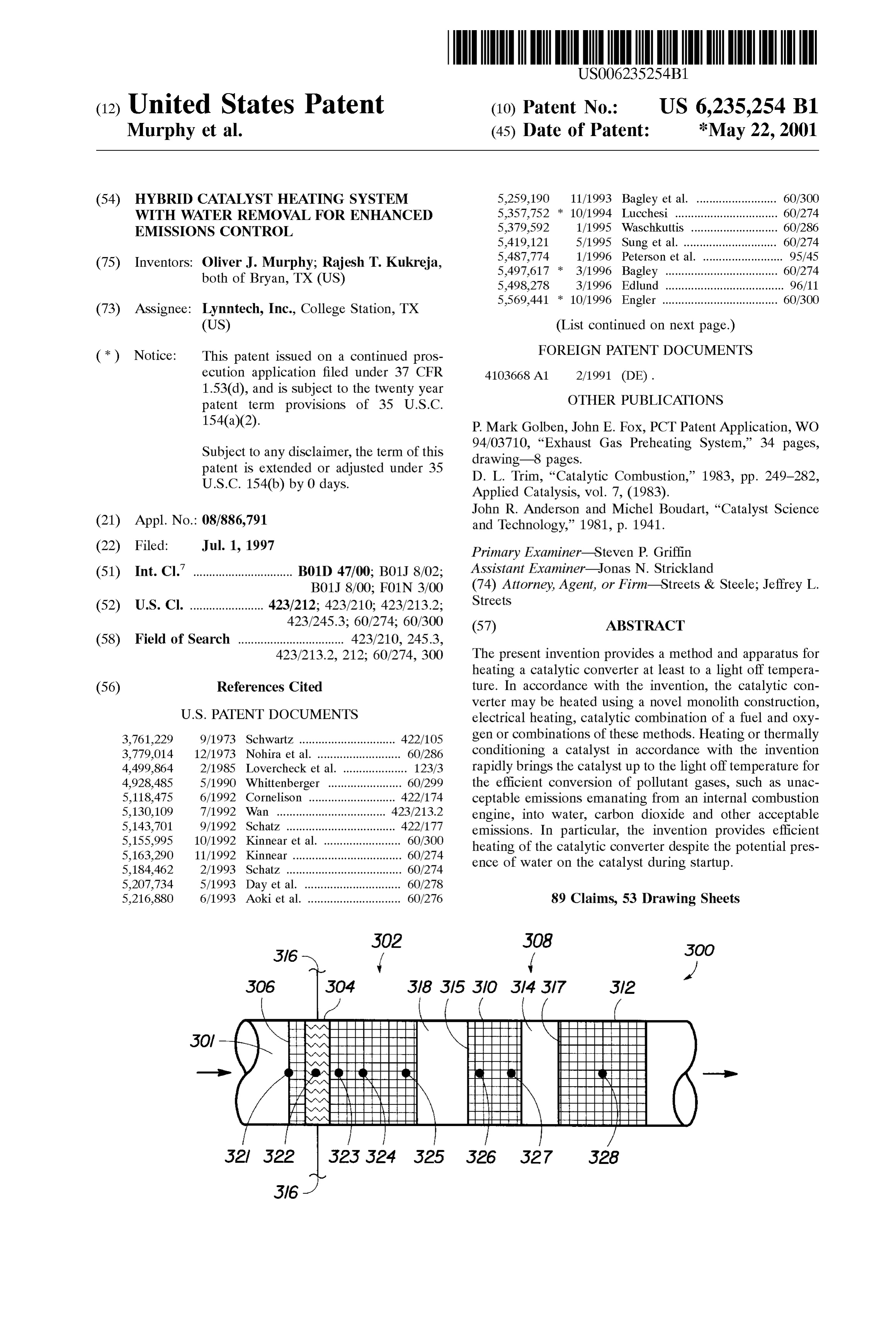
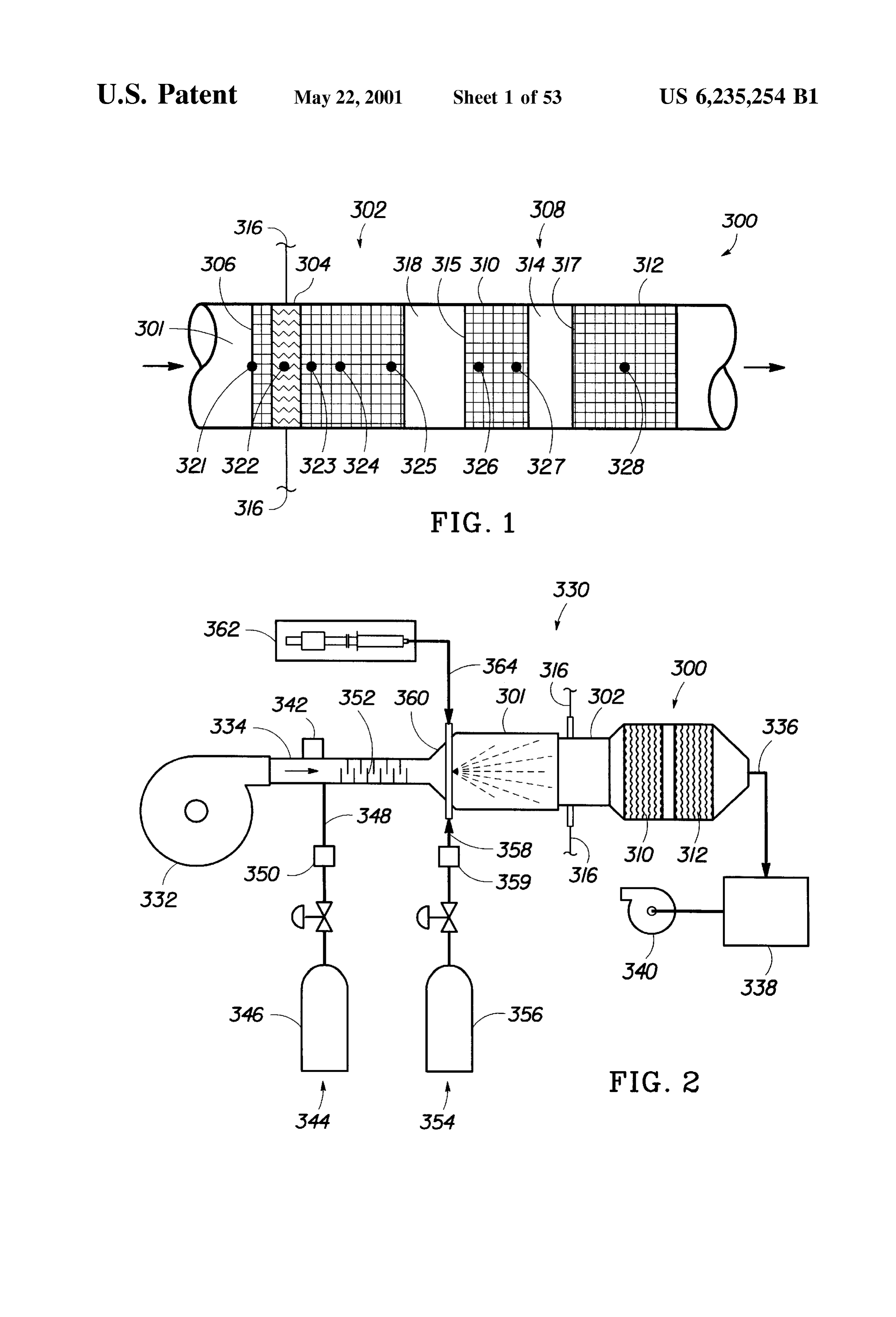
catalyst monolith. FIG. 1 is a cross-sectional view of a catalytic converter In accordance with the present invention, the catalyst System of the present invention.
monolith may be electrically heated to a temperature above about 100° C., to a temperature sufficiently high to provide forFIG. 2 is a Schematic diagram of an experimental Setup testing the catalytic converter of FIG. 1.
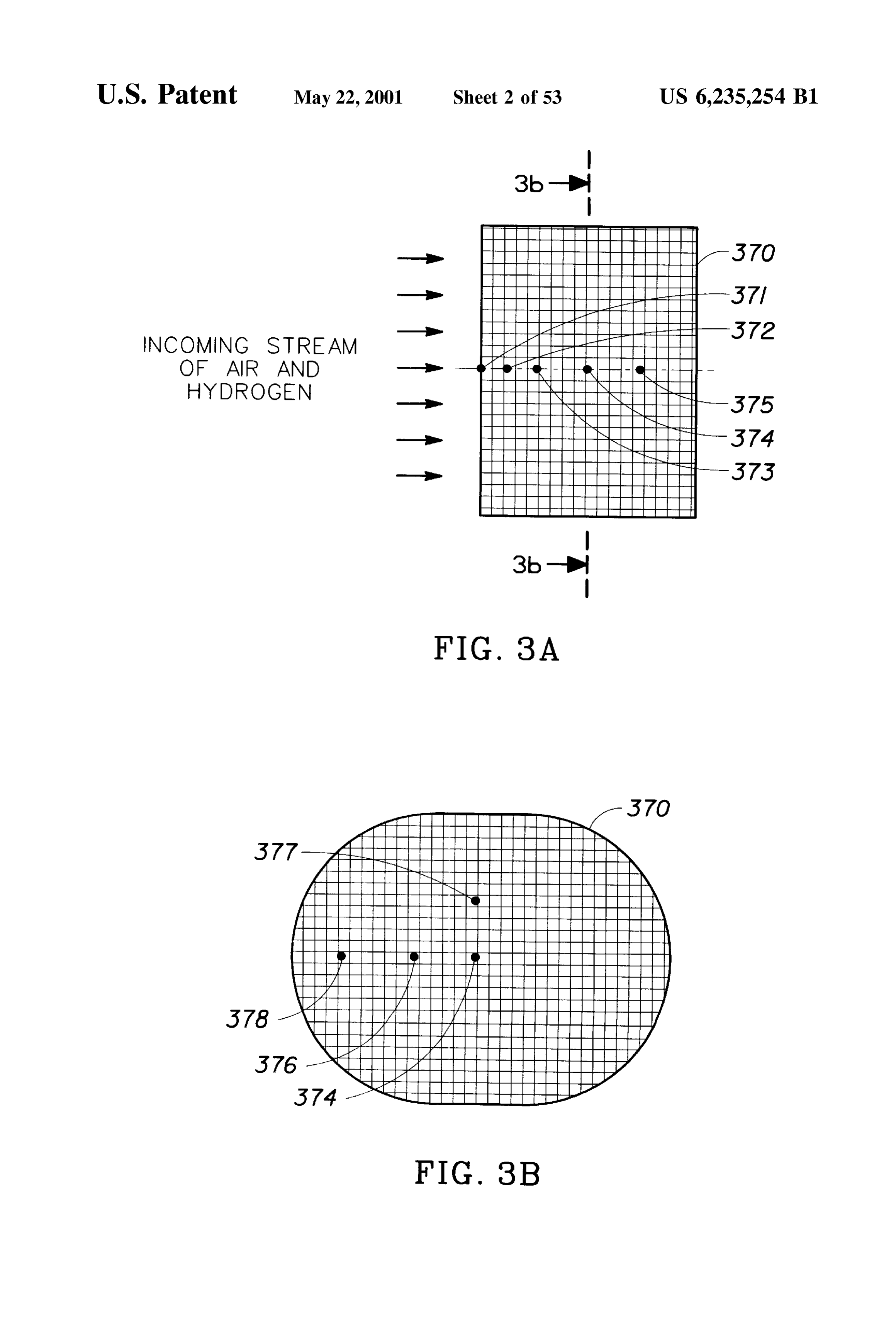
Substantially complete oxidation of the fuel, or to a tem perature above about 250 C. The catalytic combination of COnVerter. a cross-sectional view of an alternative catalytic
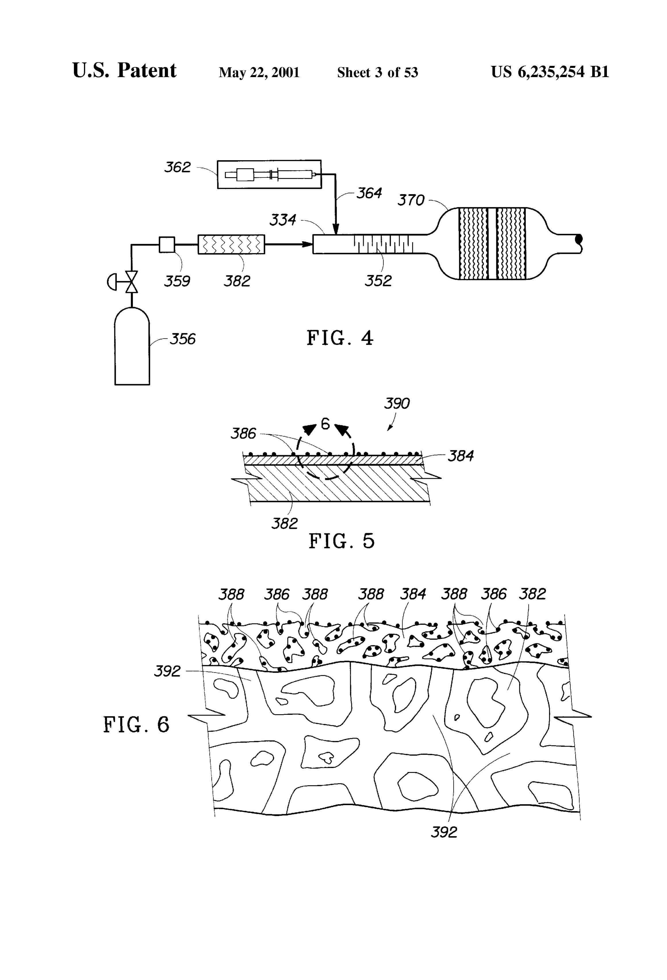
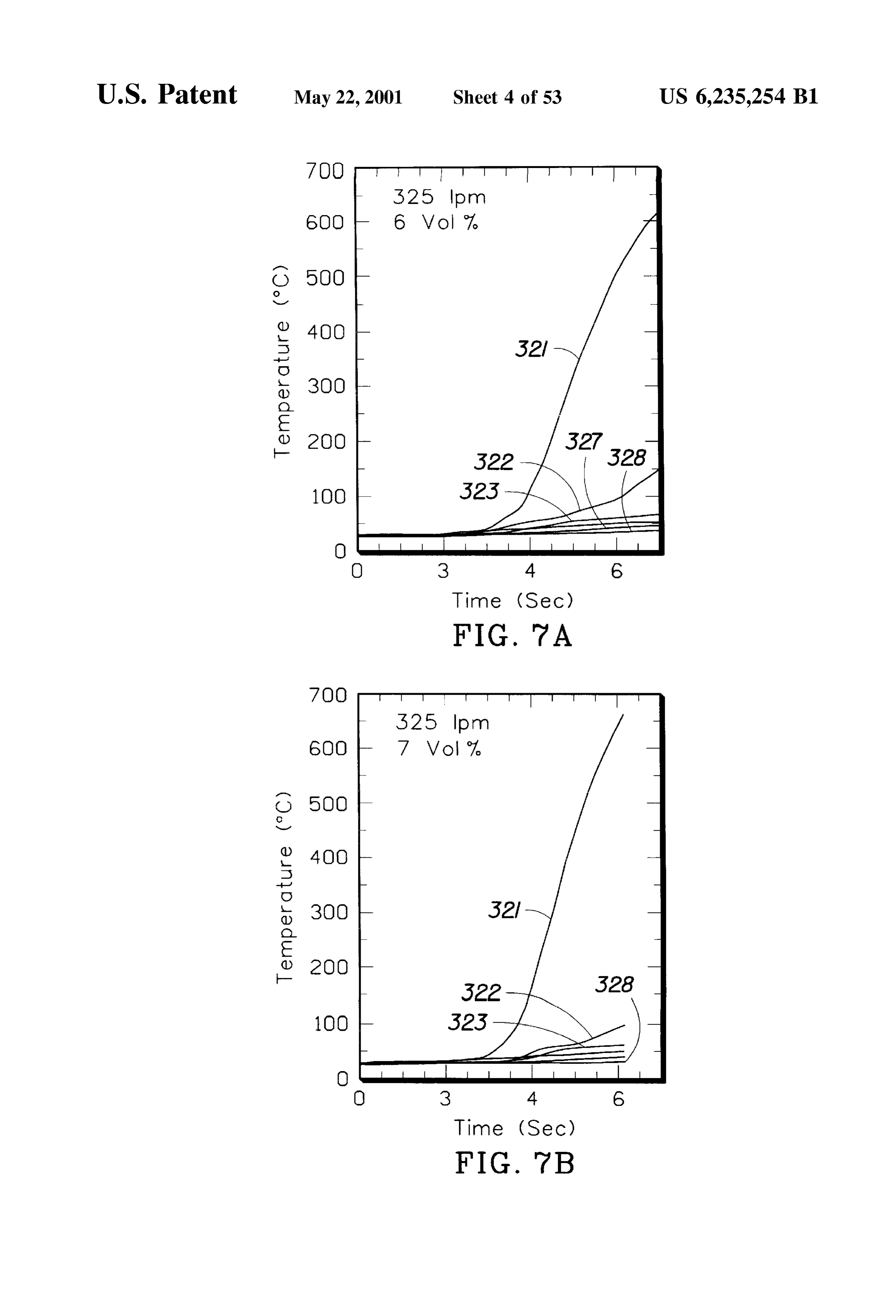
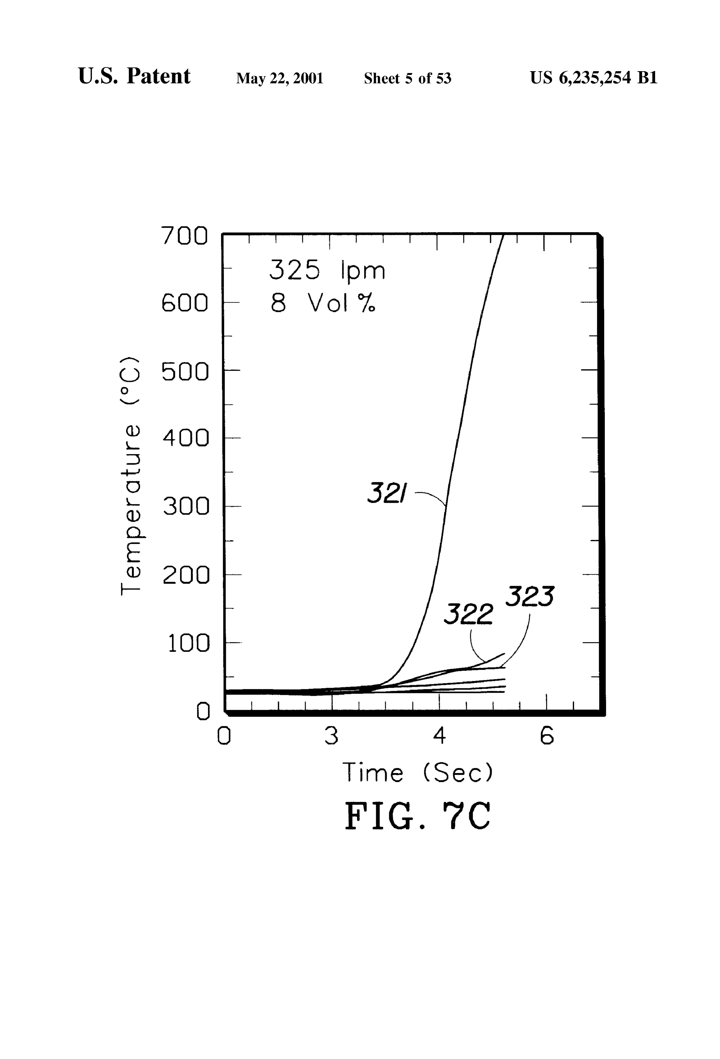
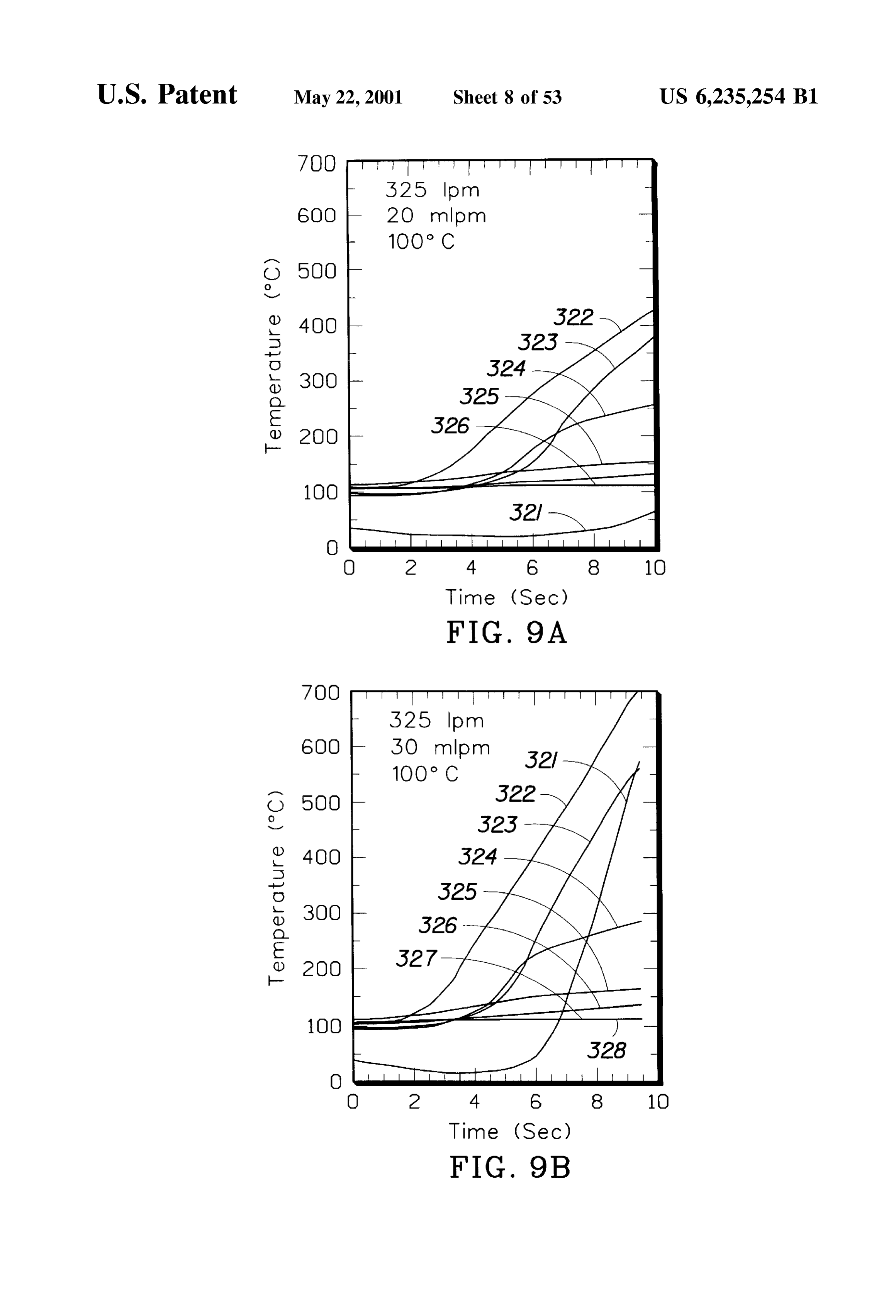
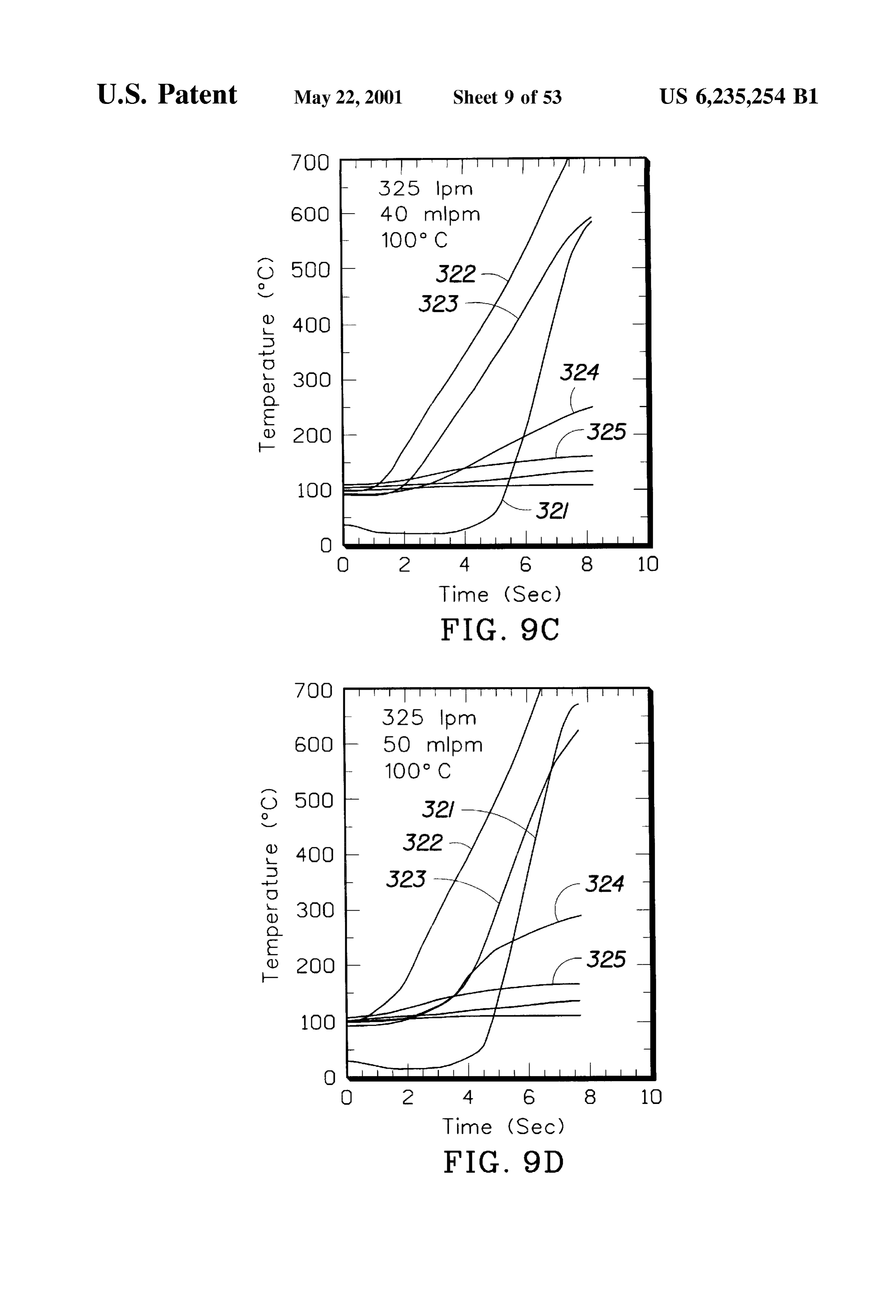
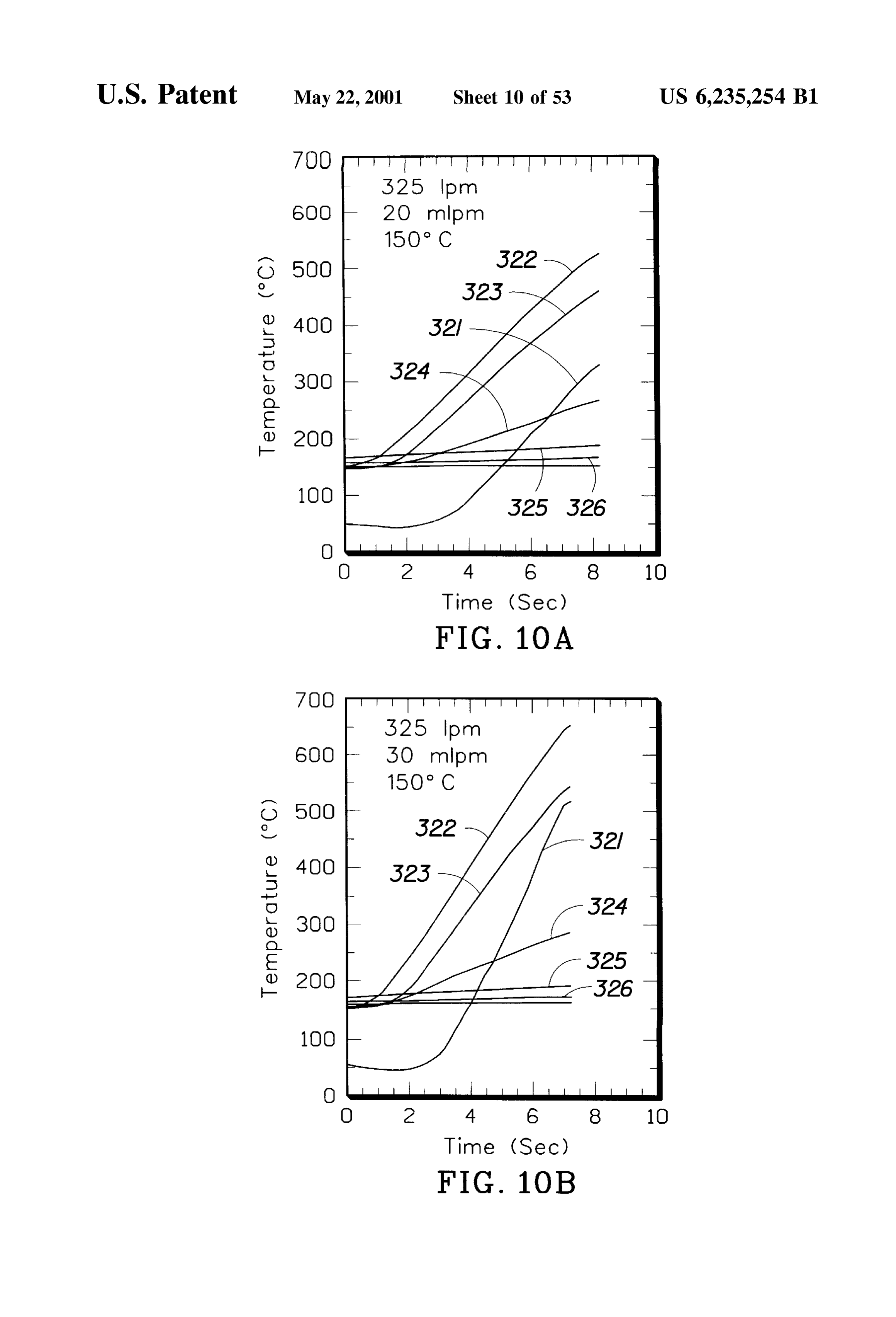
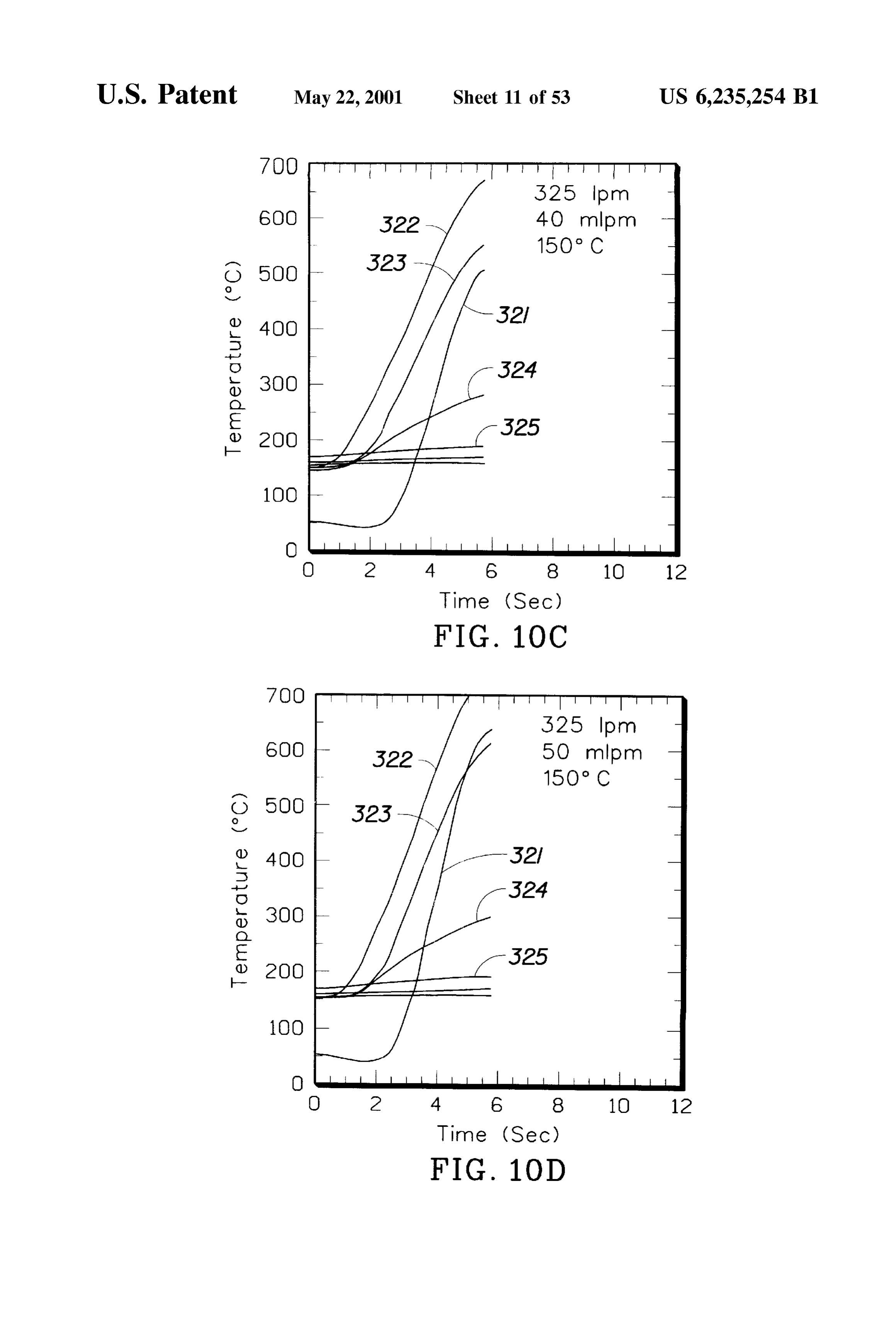
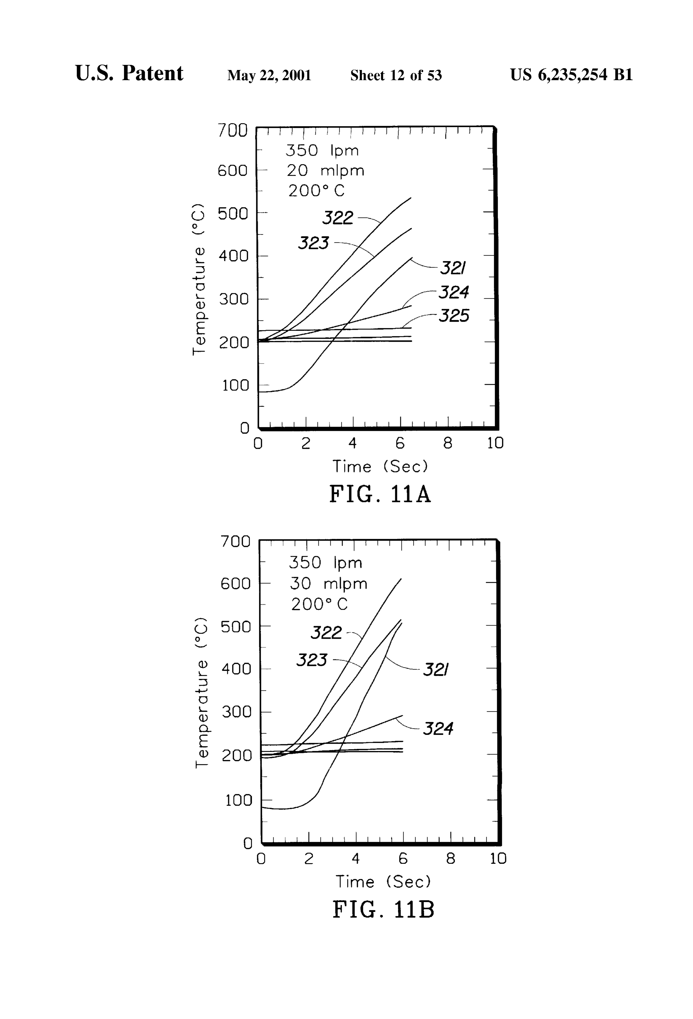
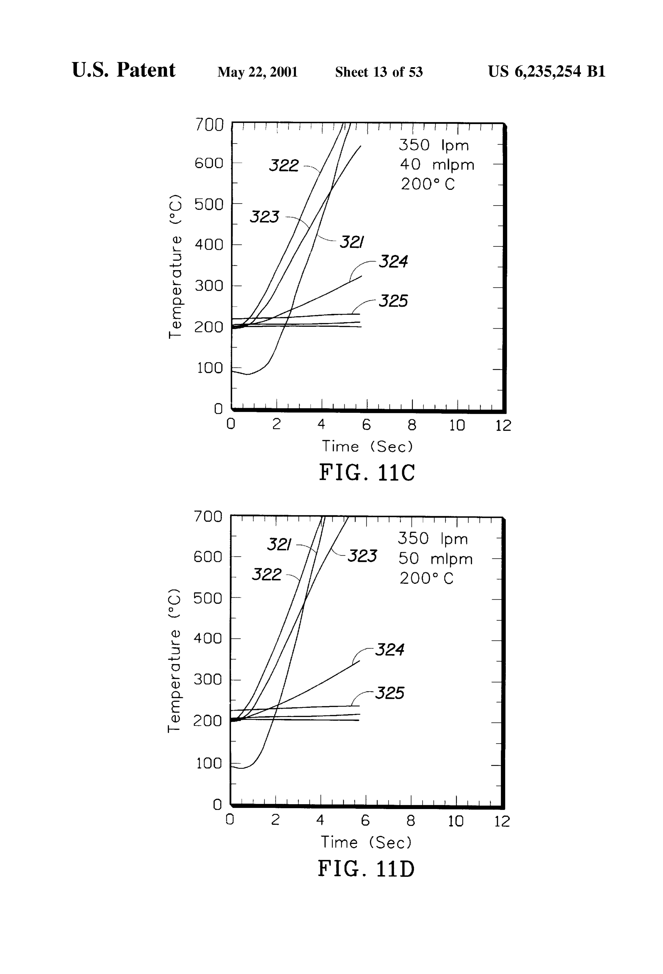
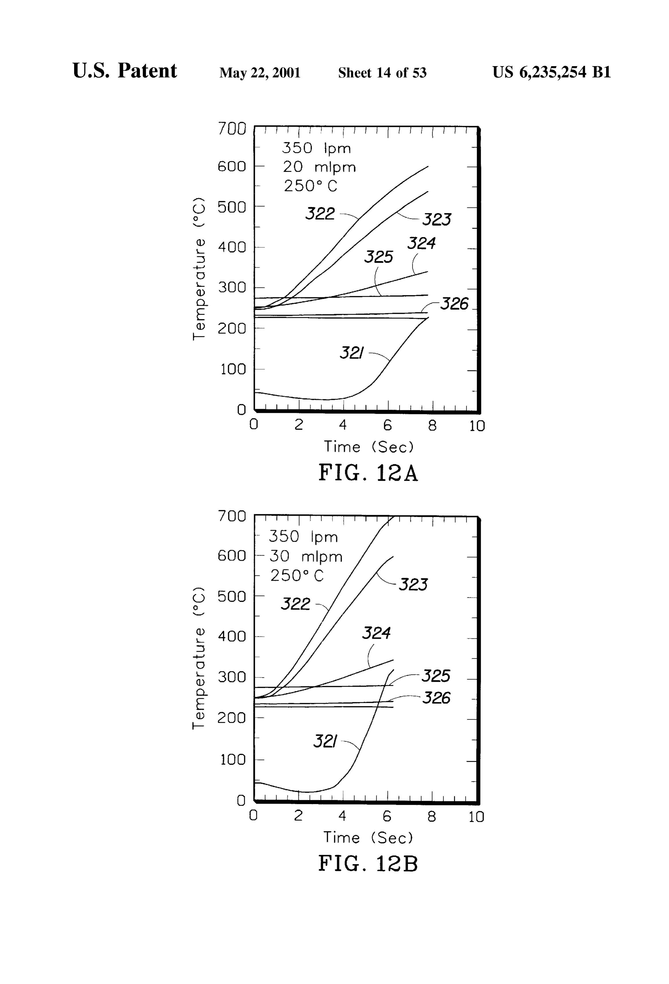
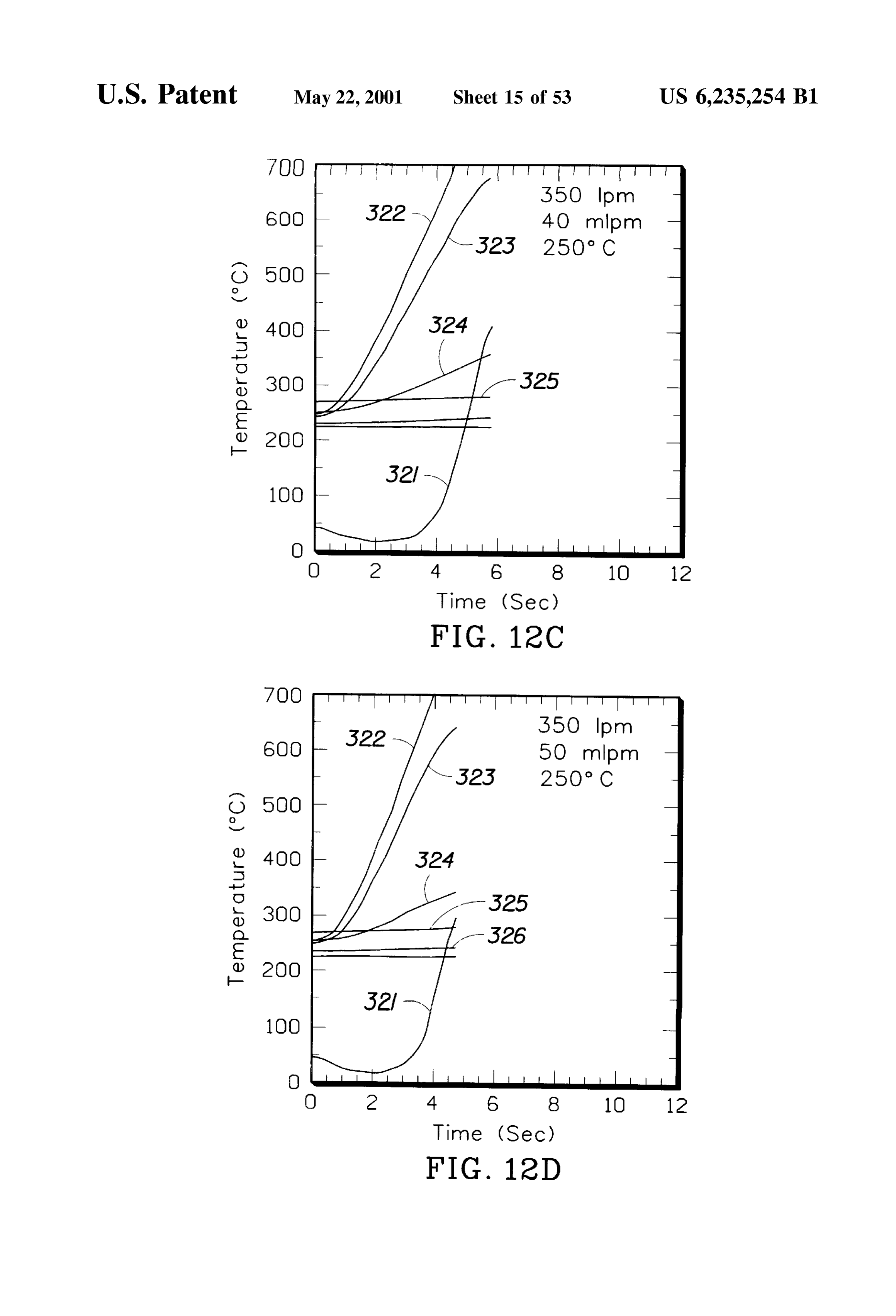
oxygen and fuel on the catalyst monolith may be provided to yield a temperature Sufficiently high to provide Substan FIG. 4 is a Schematic diagram of a Second experimental tially complete oxidation of the pollutant gas. The flow rate 25 setup for testing the catalytic converter of FIG. 3. of the fuel or the oxygen may be adjusted to obtain a desired FIG. 5 is a cross-sectional view of a catalytic converter temperature. In one embodiment of the invention, a Second monolith having a porous ceramic Substrate. fuel that undergoes low temperature catalytic oxidation is FIG. 6 is a magnified croSS-Sectional view of the porous catalytically combined with oxygen in the catalyst monolith, ceramic Substrate, washcoat and catalyst particles. wherein the Second fuel is a liquid fuel. FIG. 7 is a graph of catalyst temperature over time with The invention also includes a method of heating a of introduction of hydrogen and air into the catalytic converter catalyst, comprising the Steps of electrically heating a region FIG. 1.
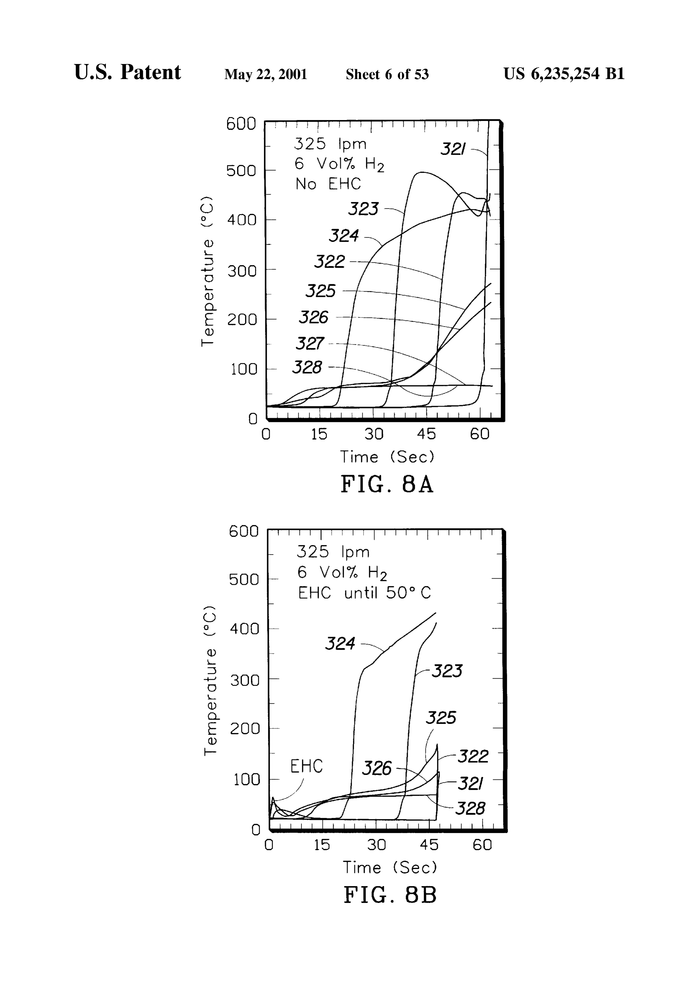
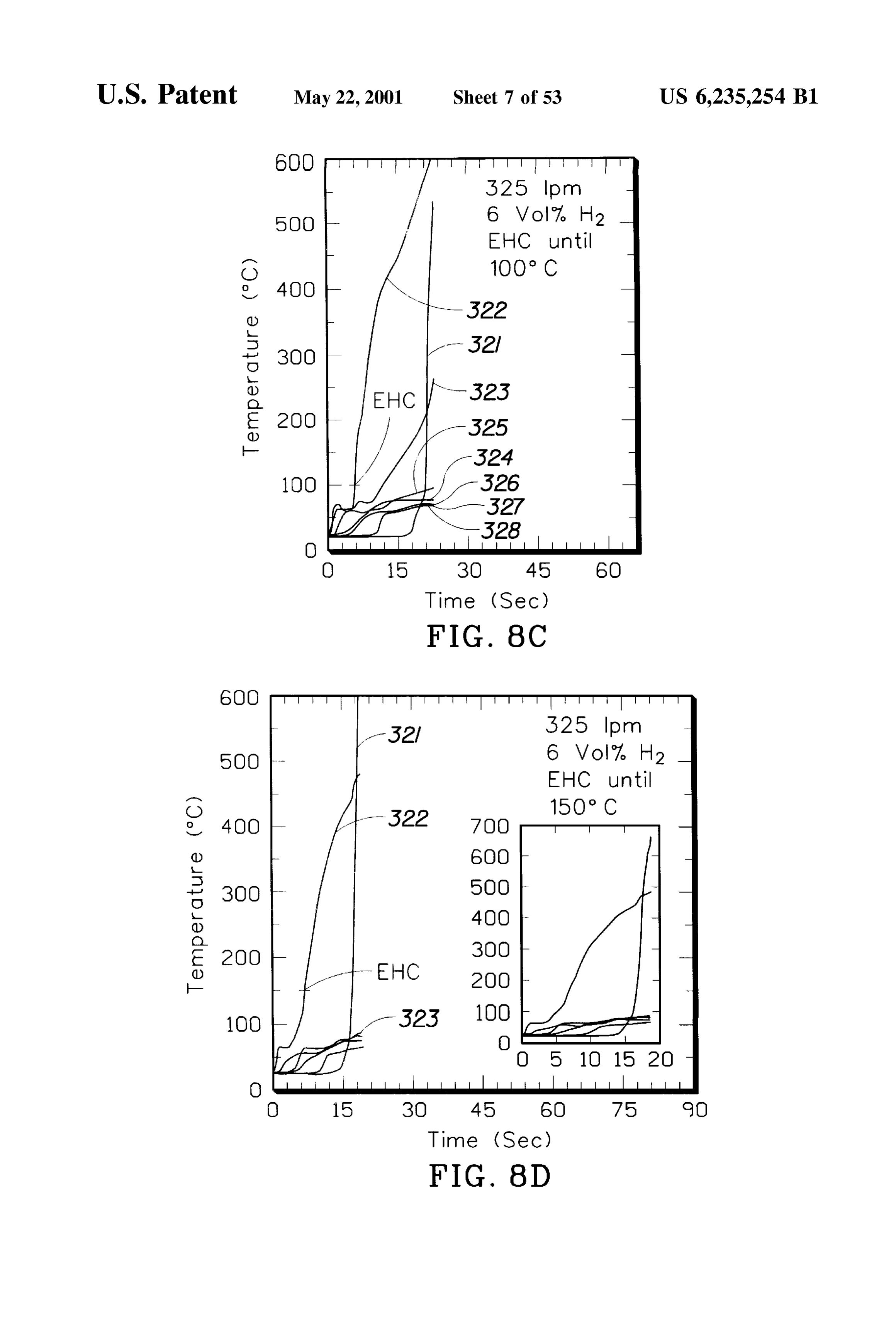
of the catalyst monolith to a first temperature, and then FIG. 8 is a graph of catalyst temperature over time chemically heating the region of the catalyst monolith to a 35 illustrating the benefits of using both electrical heating and Second temperature greater than the first temperature. The introduction of hydrogen and air into the catalytic converter Step of chemically heating may comprise combining a fuel of FIG. 1 when the catalyst is wet.
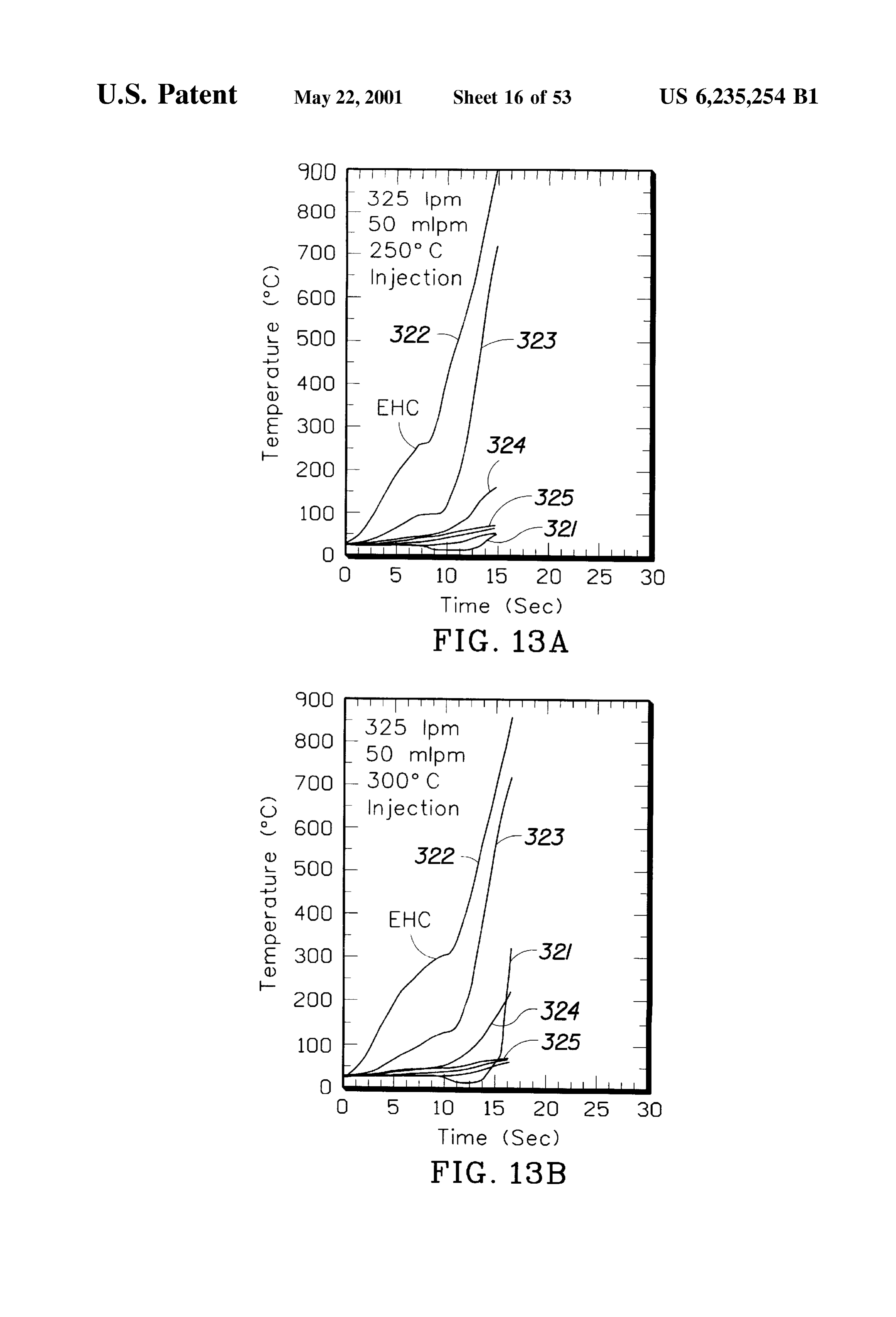
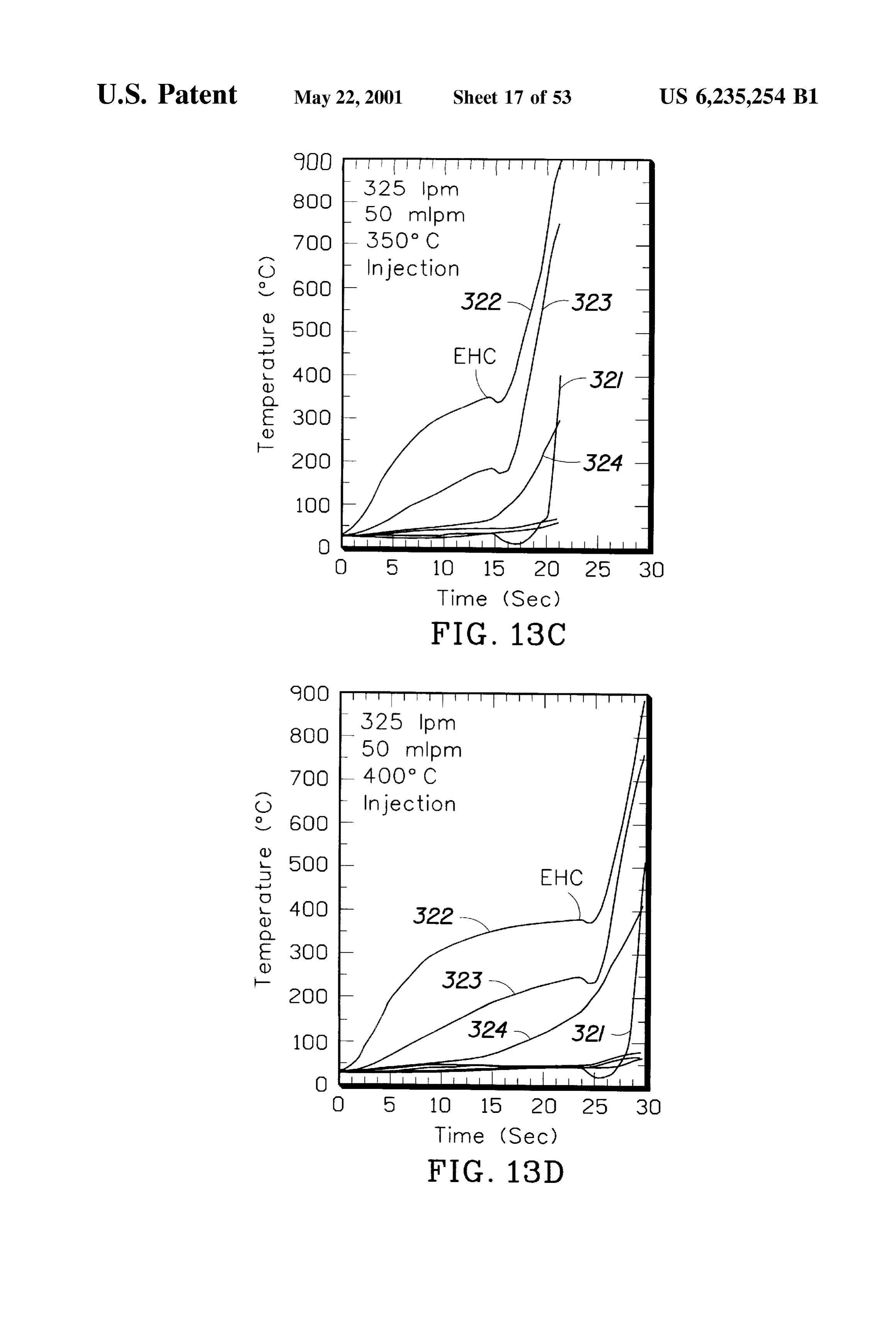
that undergoes low temperature catalytic Oxidation with FIGS. 9-12 are graphs of catalyst temperature over time OXygen. with introduction of methanol and air into the catalytic The invention also provides a catalyst bed, comprising a 40 converter of FIG. 1 initially at a steady state temperature of porous Substrate, a porous washcoat covering a Surface of 100° C., 150° C., 200° C. and 250° C., respectively. the porous Substrate, and catalyst particles exposed over a FIG. 13 is a graph of catalyst temperature over time Surface of the Washcoat, wherein the Washcoat and ceramic illustrating the benefits of using both electrical heating and Substrate have Sufficient porosity to draw condensates into introduction of methanol and air into the catalytic converter the ceramic substrate. Preferably the porous metal or 45 of FIG. 1.
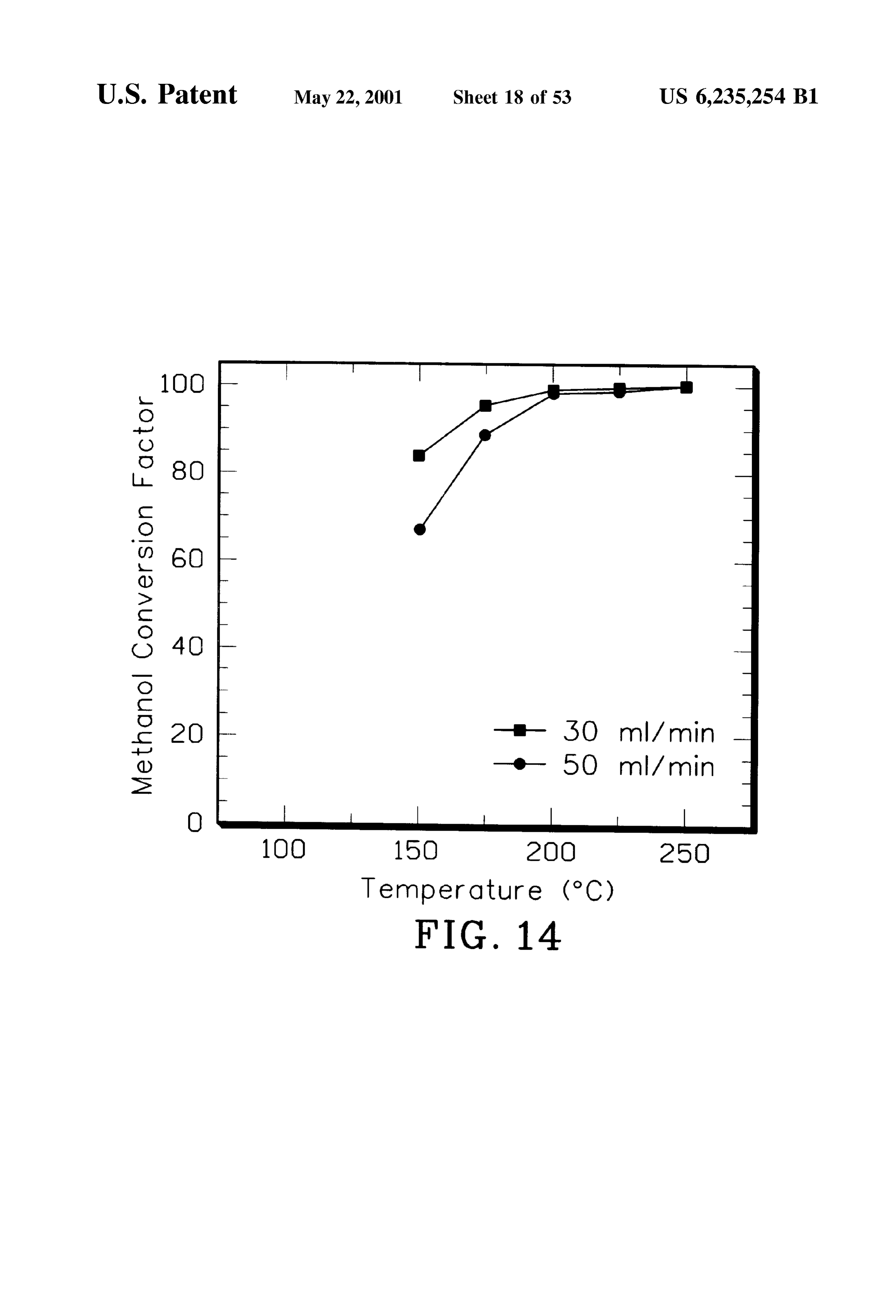
ceramic Substrate is hydrophilic and may contain both FIG. 14 is a graph of methanol conversion factor as a nano-pores and micro-pores, perhaps having pores with a function of the catalyst monolith Steady State temperature diameter between about 5 and about 1000 Angstroms. prior to introducing methanol.
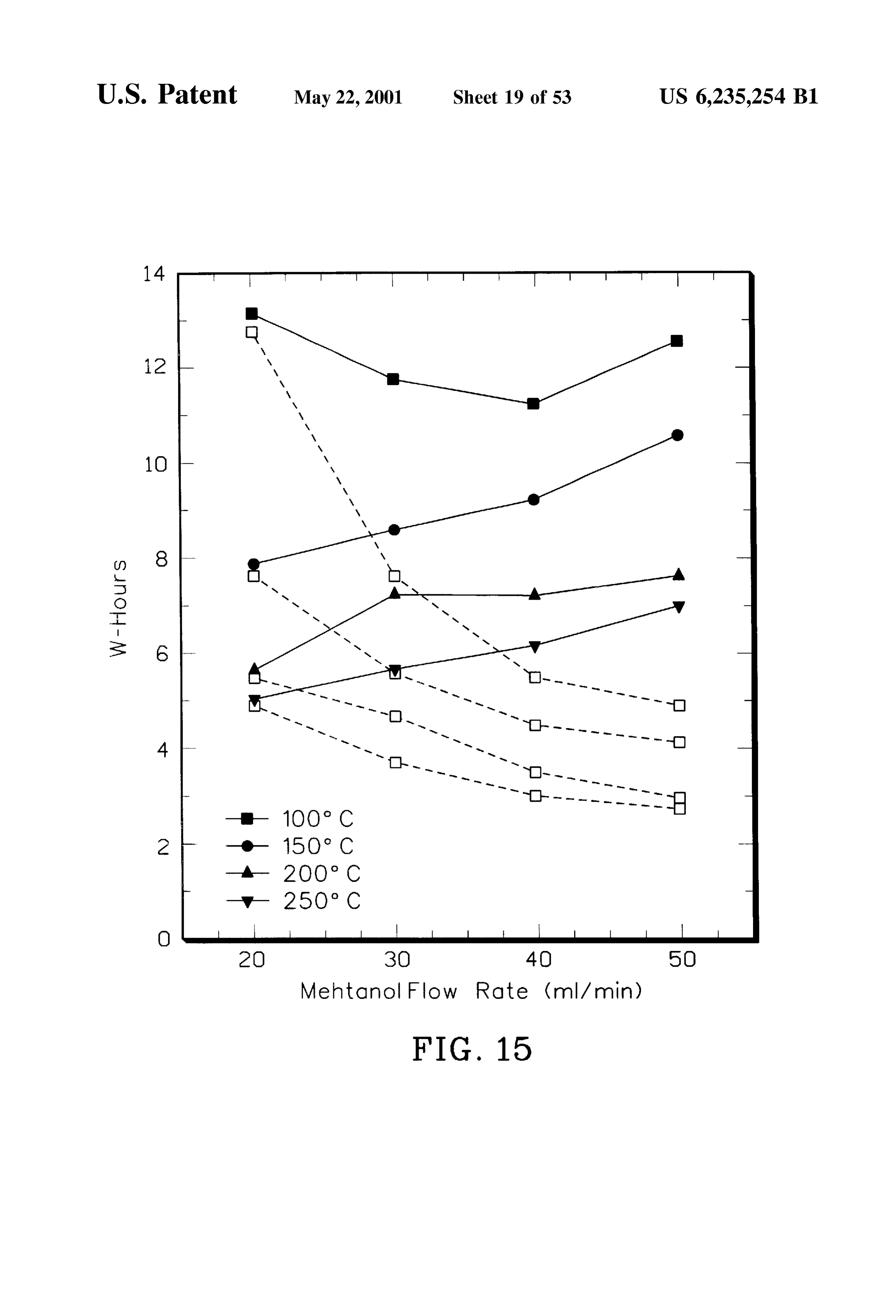
Porous metal Substrates may comprise Sintered metal par FIG. 15 is a graph of the chemical energy required and the ticles and may be electrically conductive to form a resistive 50 time to reach 400 C. in a catalyst monolith preheated element of an electrical heater. electrically under steady state conditions to 100° C., 150 C., The invention further provides a System for heating a 200° C. and 250° C.
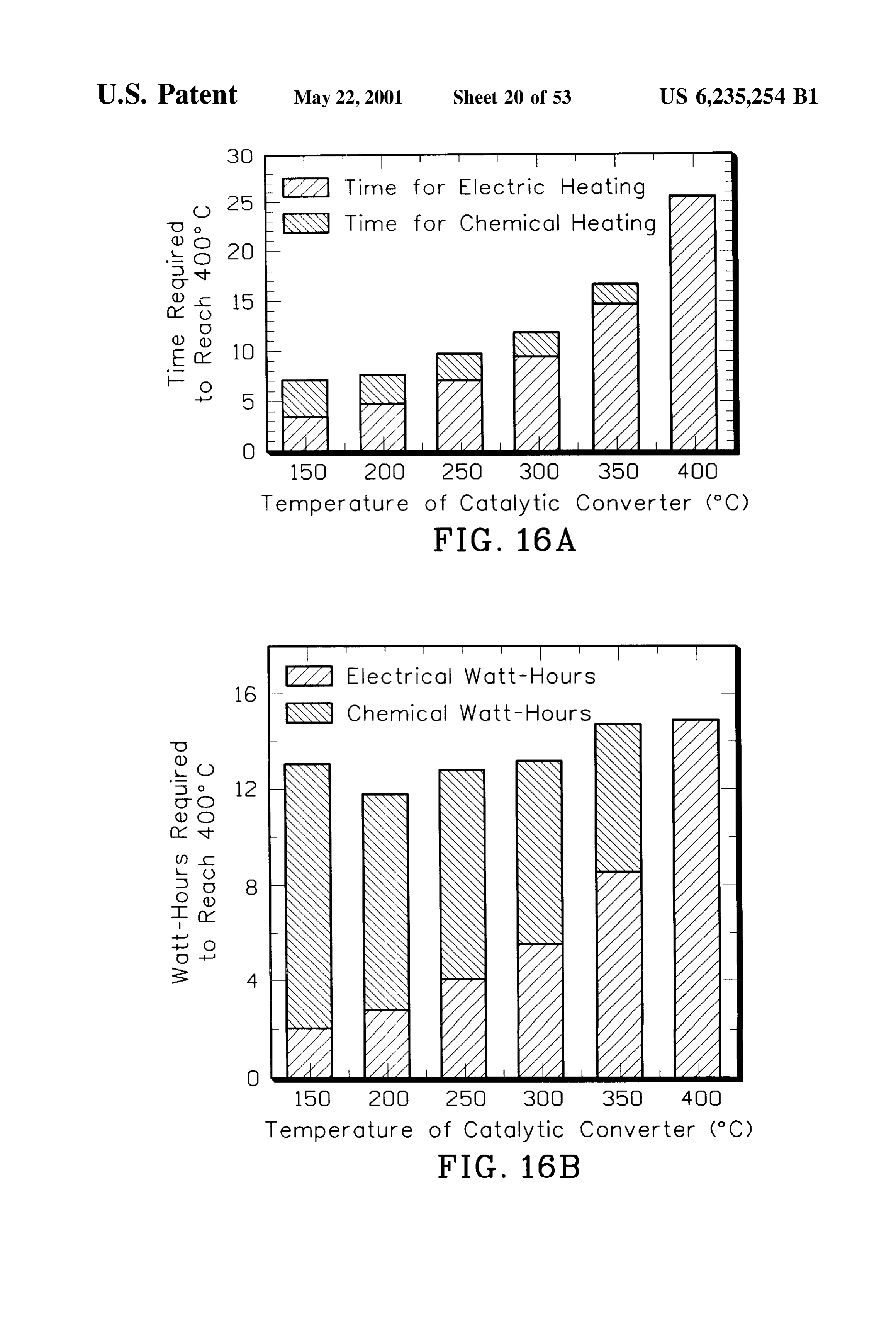
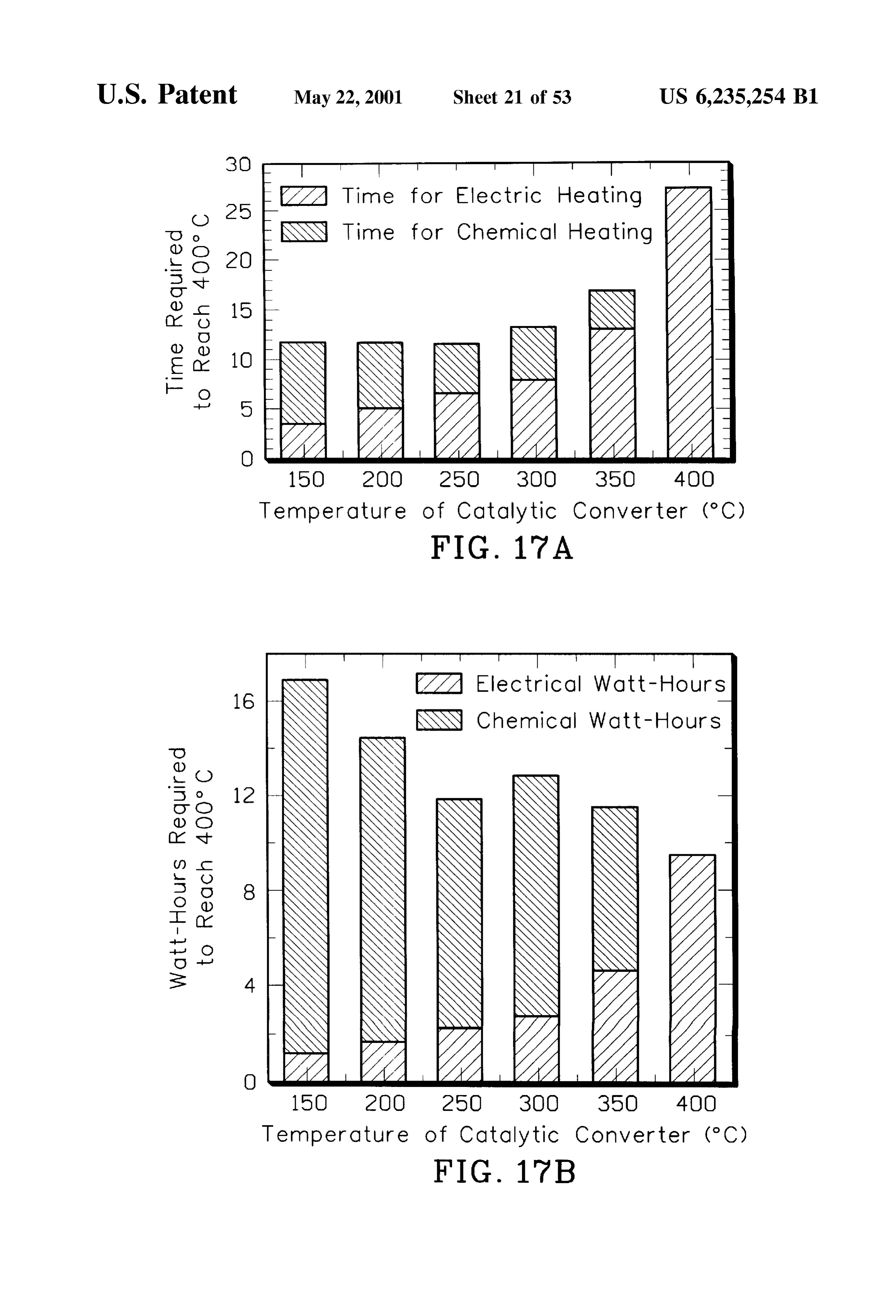
catalyst monolith in an exhaust gas line, comprising an FIGS. 16 and 17 each show two bar charts illustrating the electrical heater in thermal communication with a region of time and energy required for the catalyst to reach 400° C. as the catalyst monolith, a fuel Source, and a conduit disposed 55 a function of the catalyst temperature at which methanol between the fuel source and the catalyst monolith. The injection was commenced.
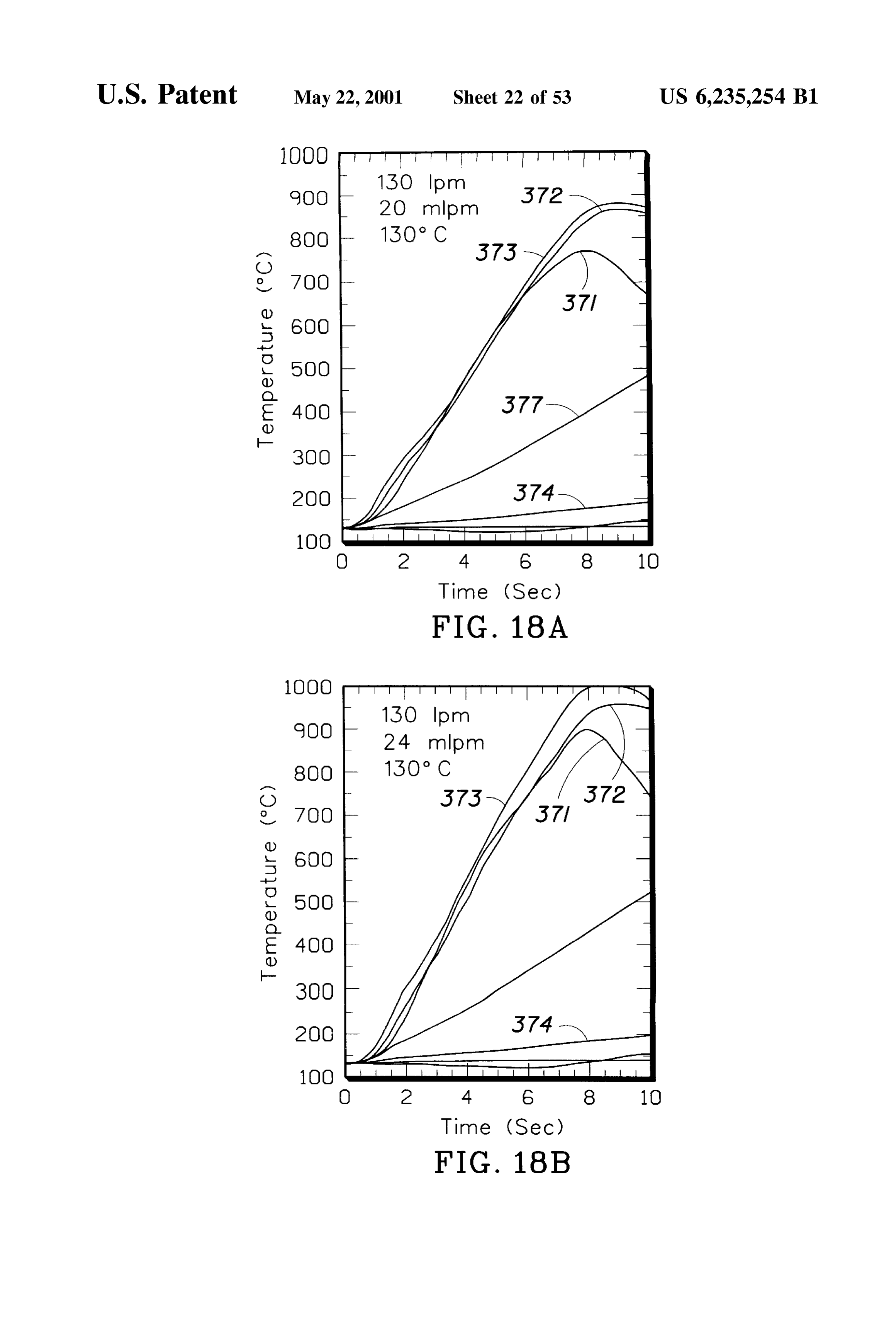
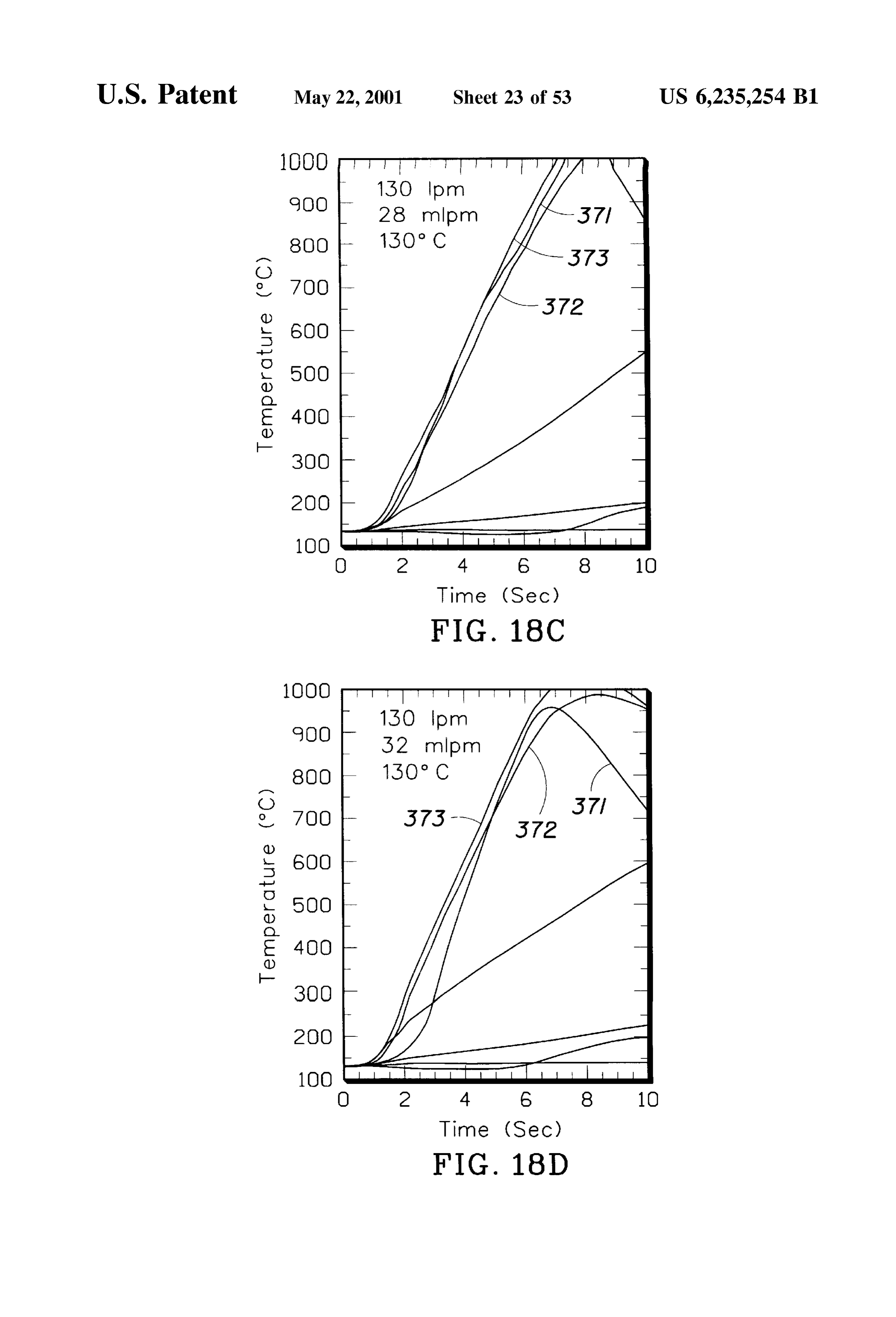
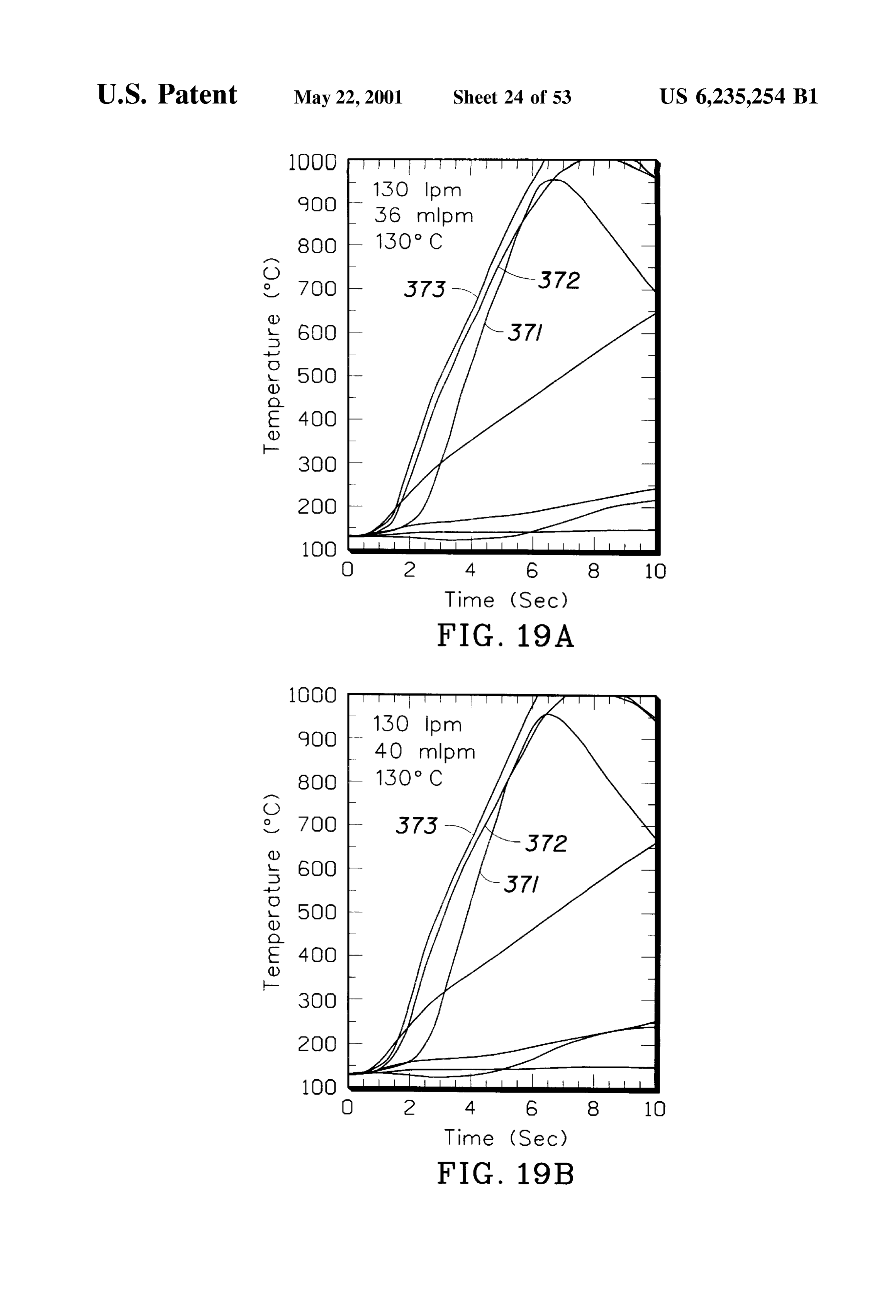
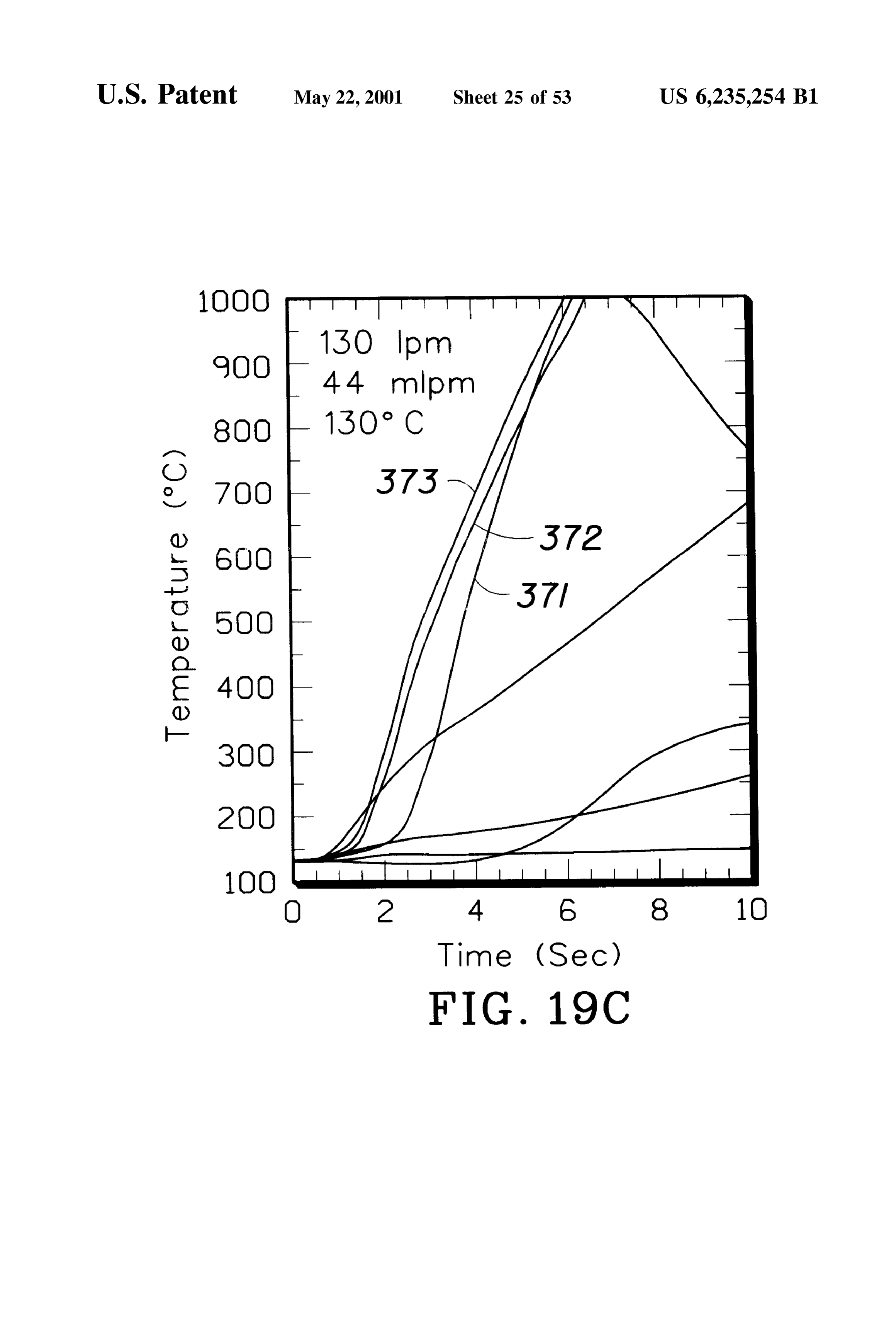
electrical heater may comprise a Second catalyst monolith FIGS. 18 and 19 are graphs of catalyst temperature over having a metal Substrate. Further, the electrical heater may time with introduction of trimethoxymethane at various flow be disposed in the exhaust gas line upstream from the rates and air into the catalytic converter of FIG. 3 preheated catalyst monolith. Preferably, the system will further com 60 at 130° C.
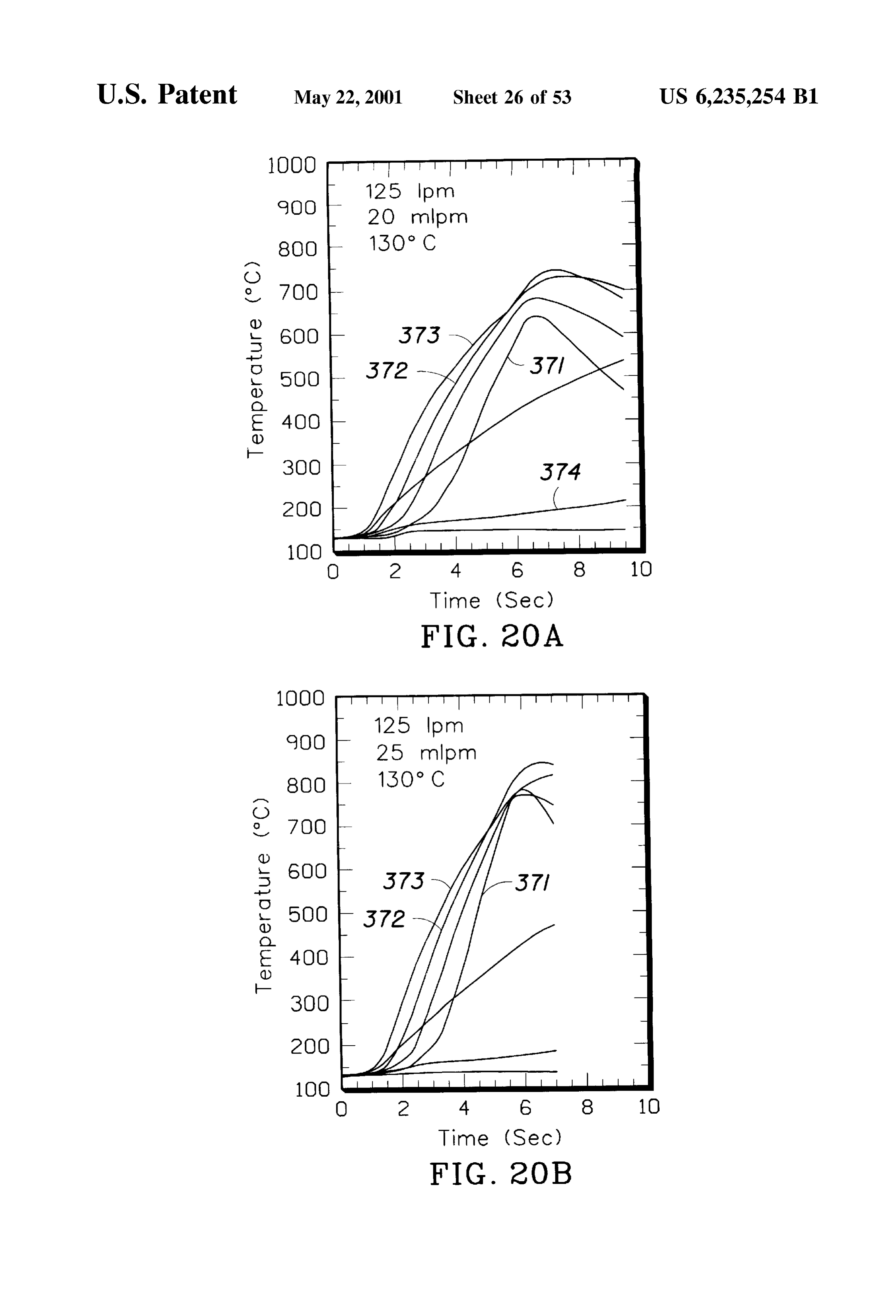
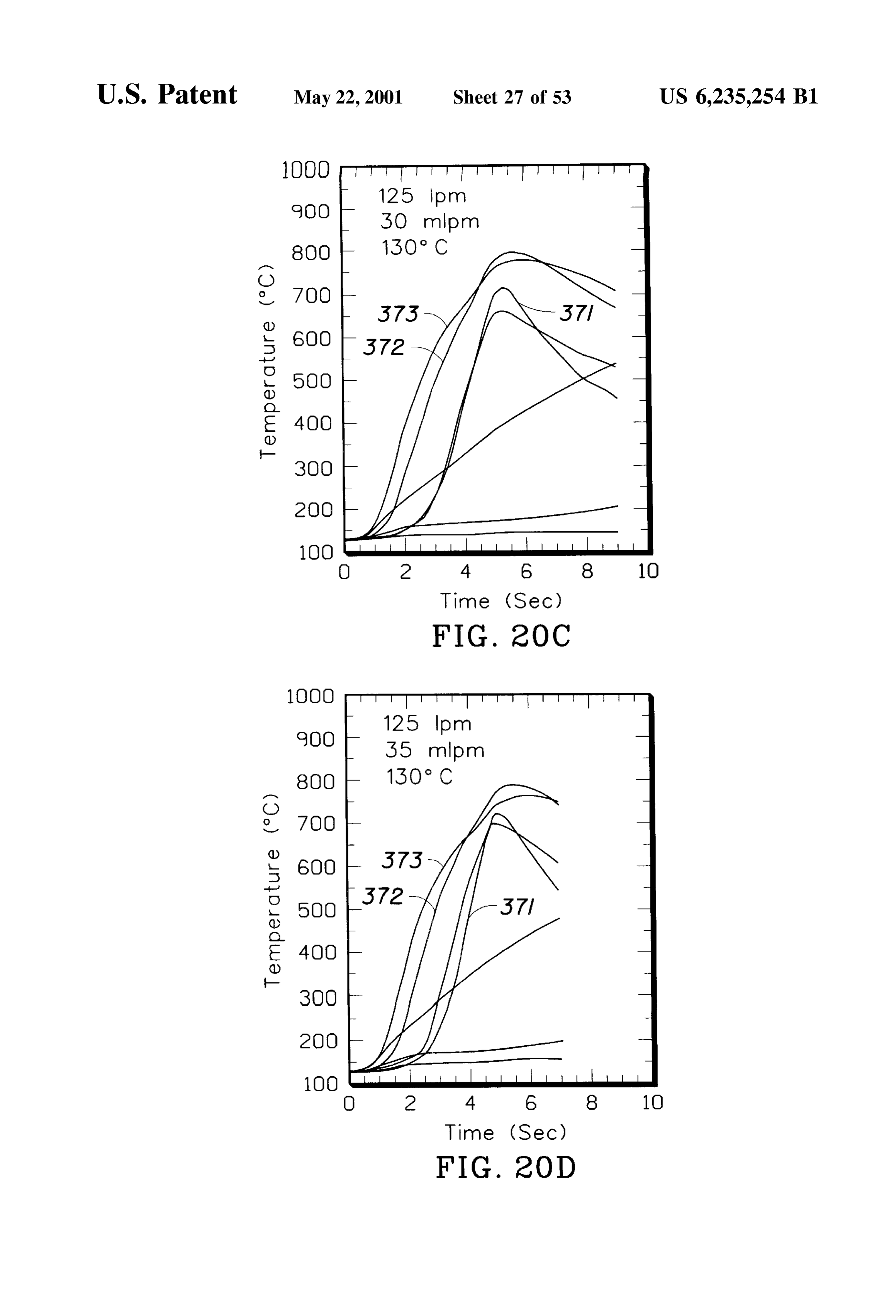
prise a flow control member disposed in the conduit. The FIG. 20 is a graph of catalyst temperature over time with fuel Source may be a hydrogen generator, Such as an introduction of dimethoxymethane at various flow rates and electrolyzer, or any Suitable fluid container. Additionally, the air into the catalytic converter of FIG. 3 preheated at 130 System may further include an oxygen Source Selected from C.
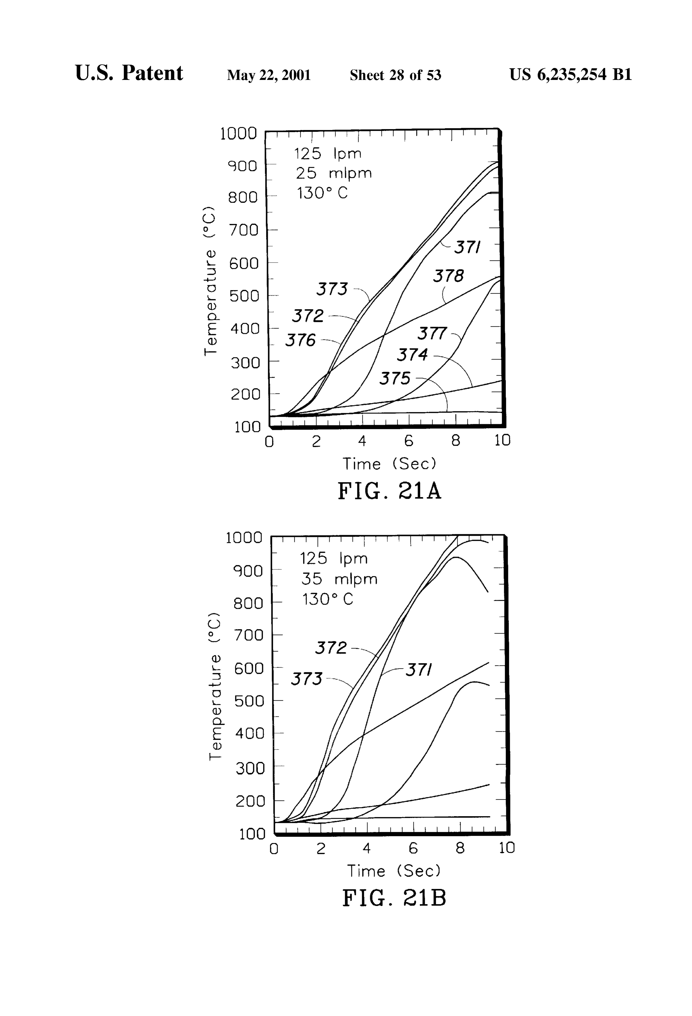
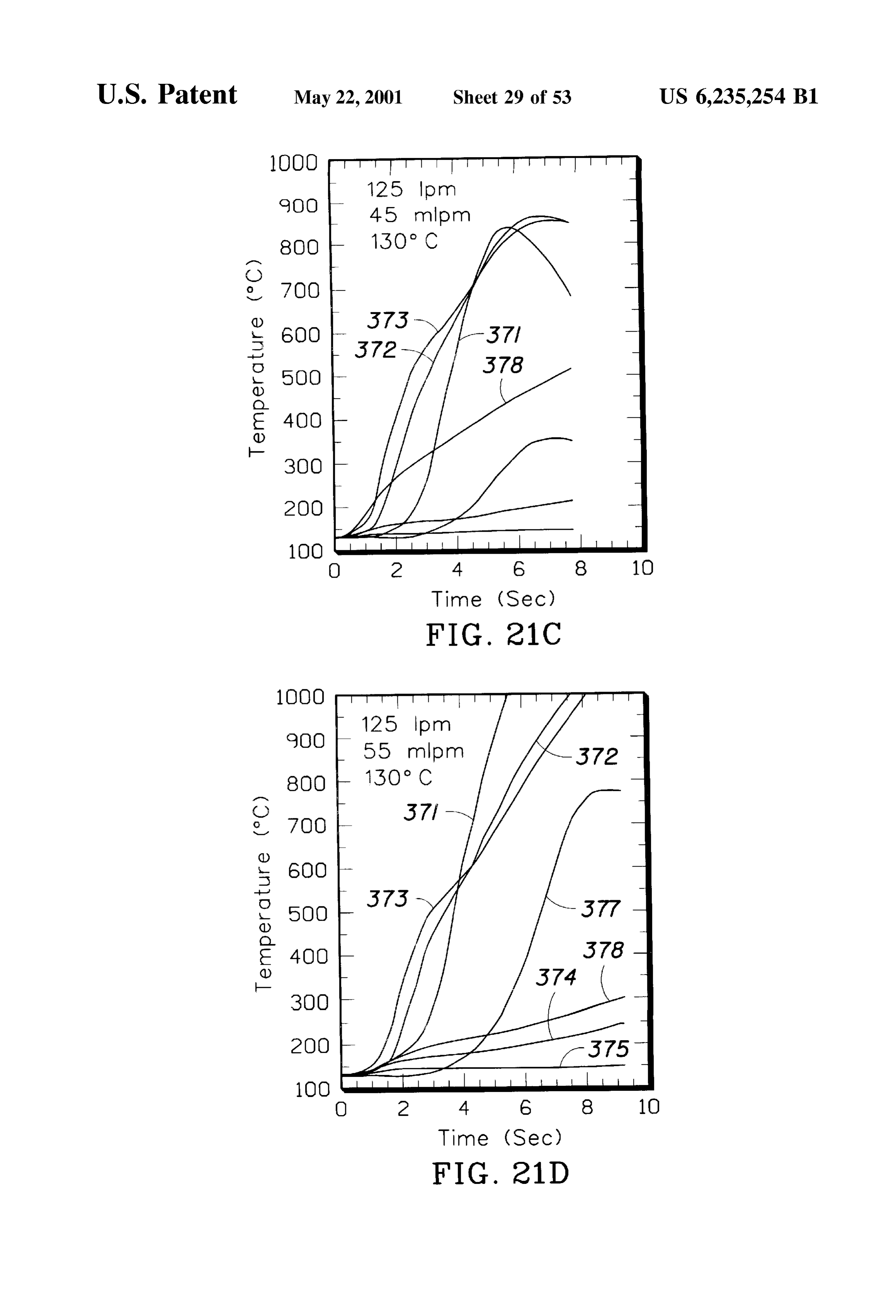
air, Stored oxygen and an oxygen producing electrolyzer. 65 FIG. 21 is a graph of catalyst temperature over time with Yet another aspect of the invention provides an electri introduction of methyl formate at various flow rates and air cally heated device for catalytic conversion of exhaust gases into the catalytic converter of FIG. 3 preheated at 130 C.
Page 59
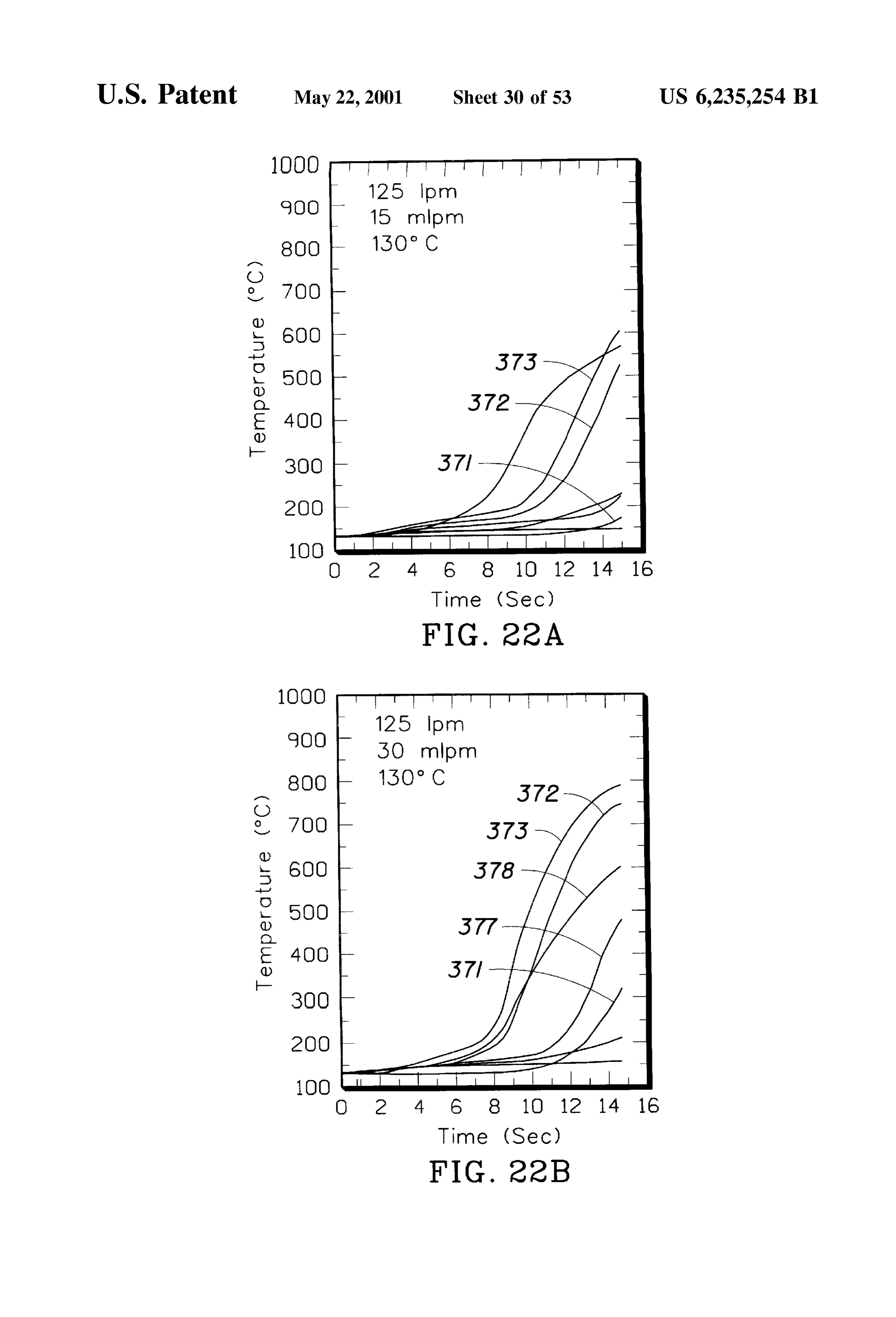
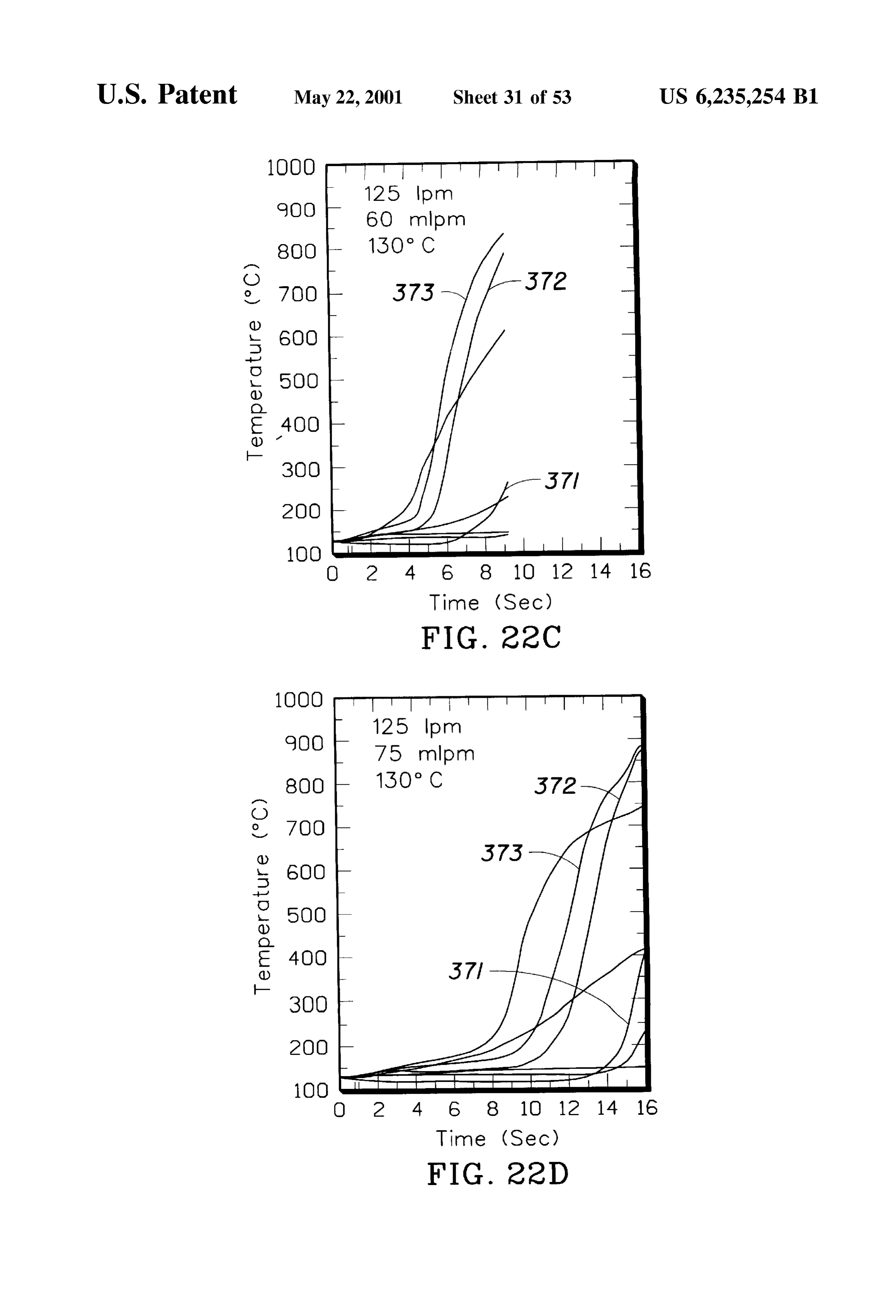
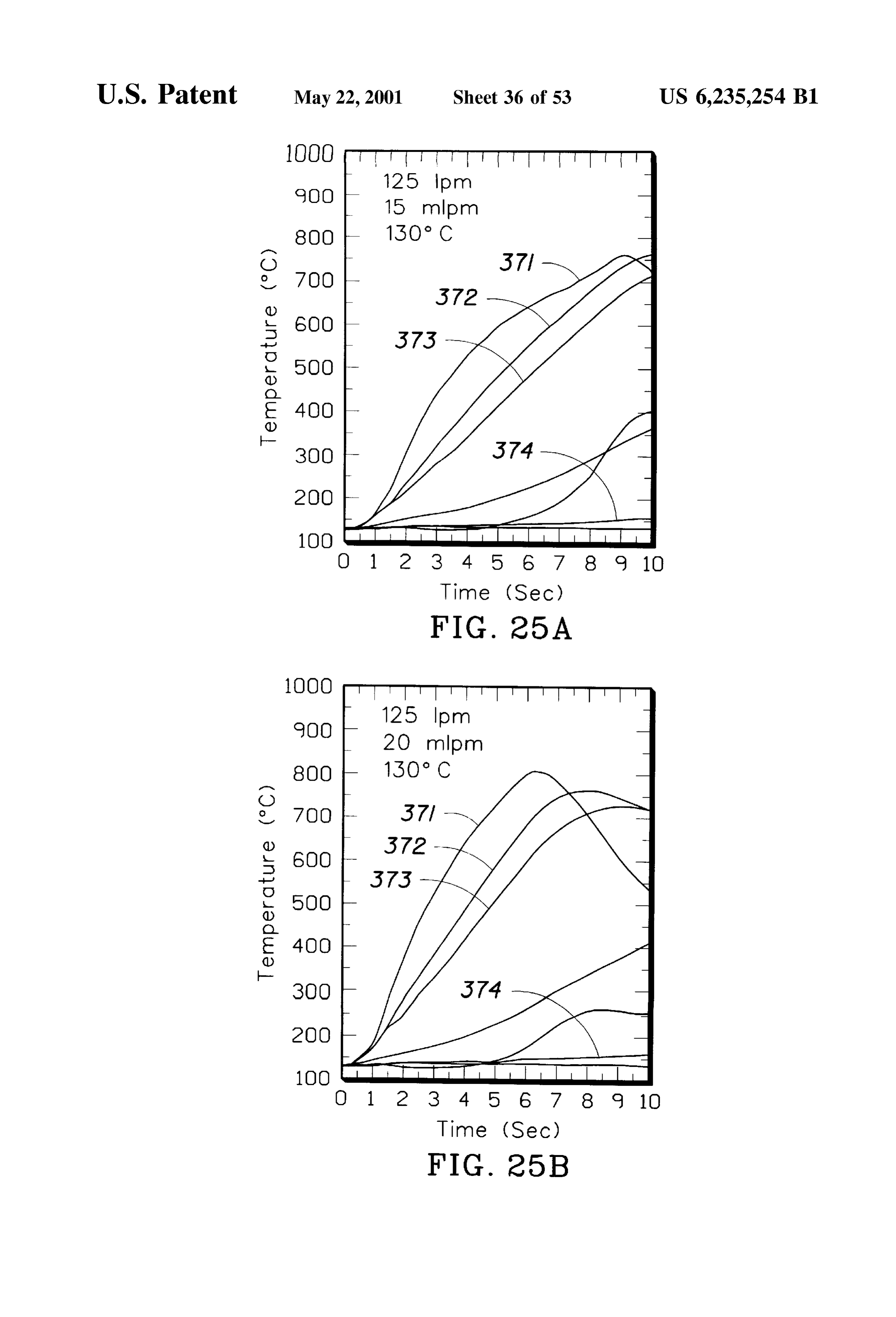
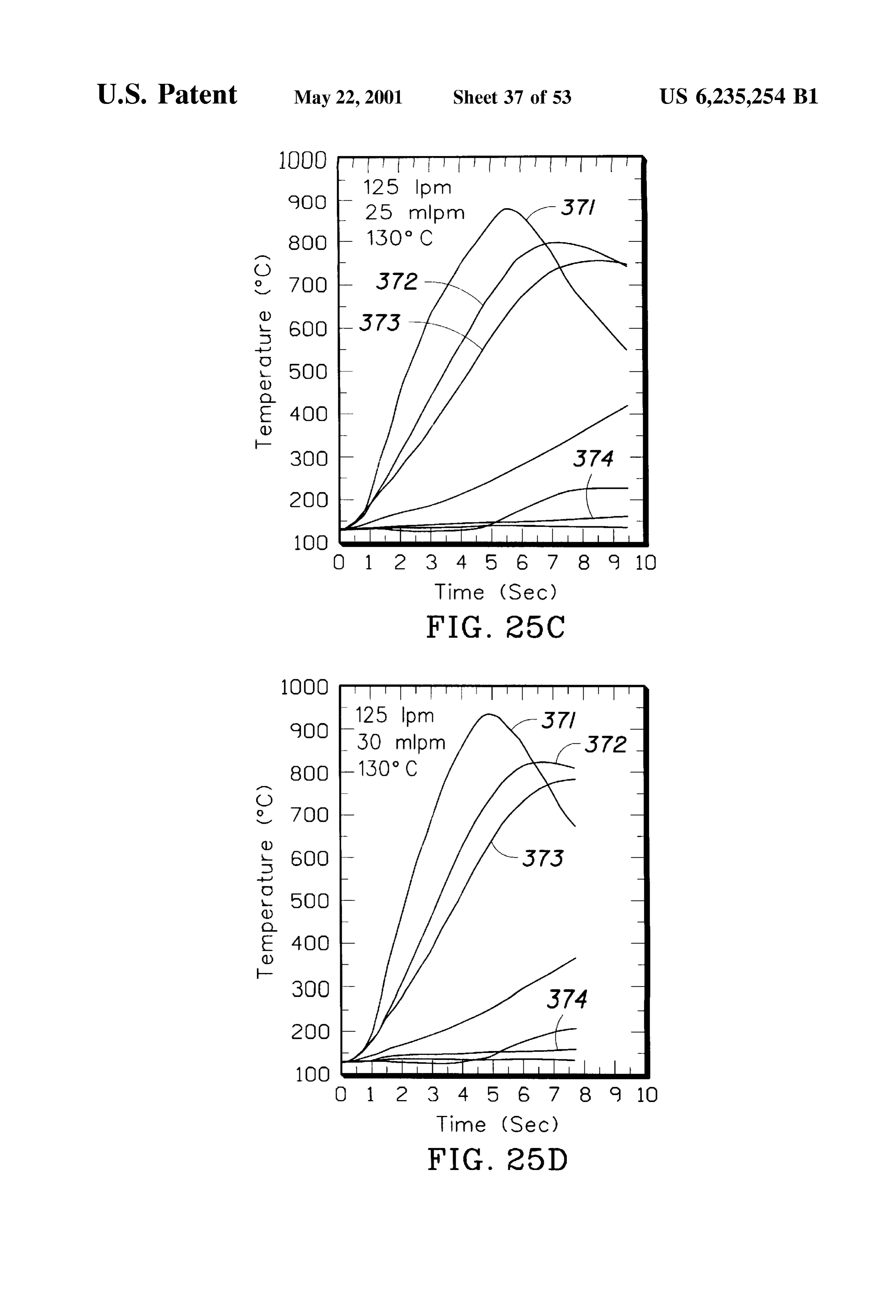
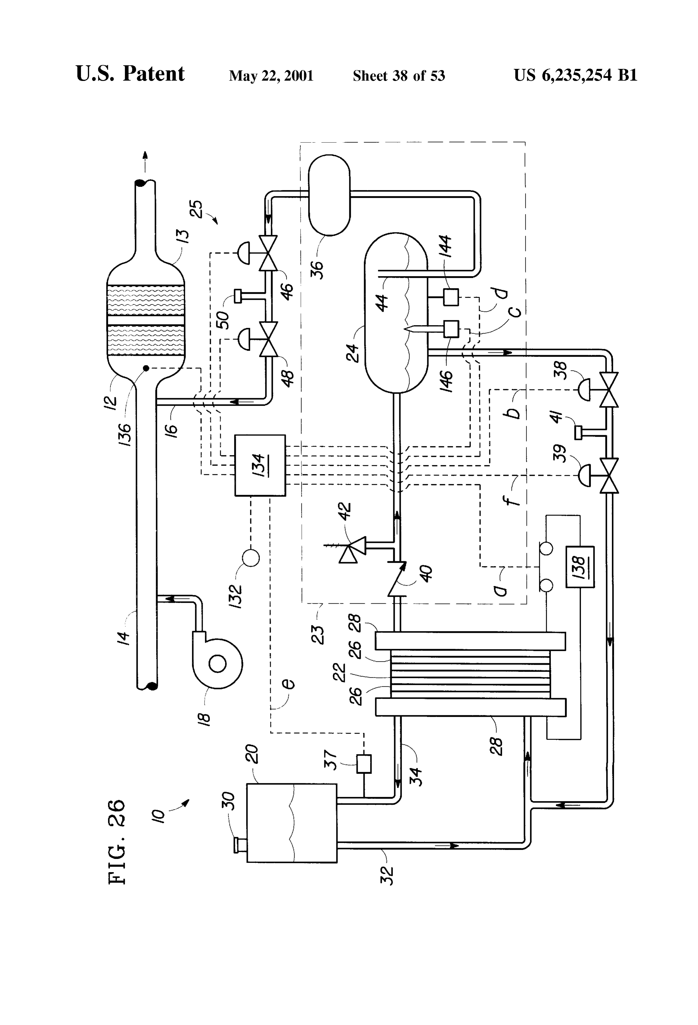
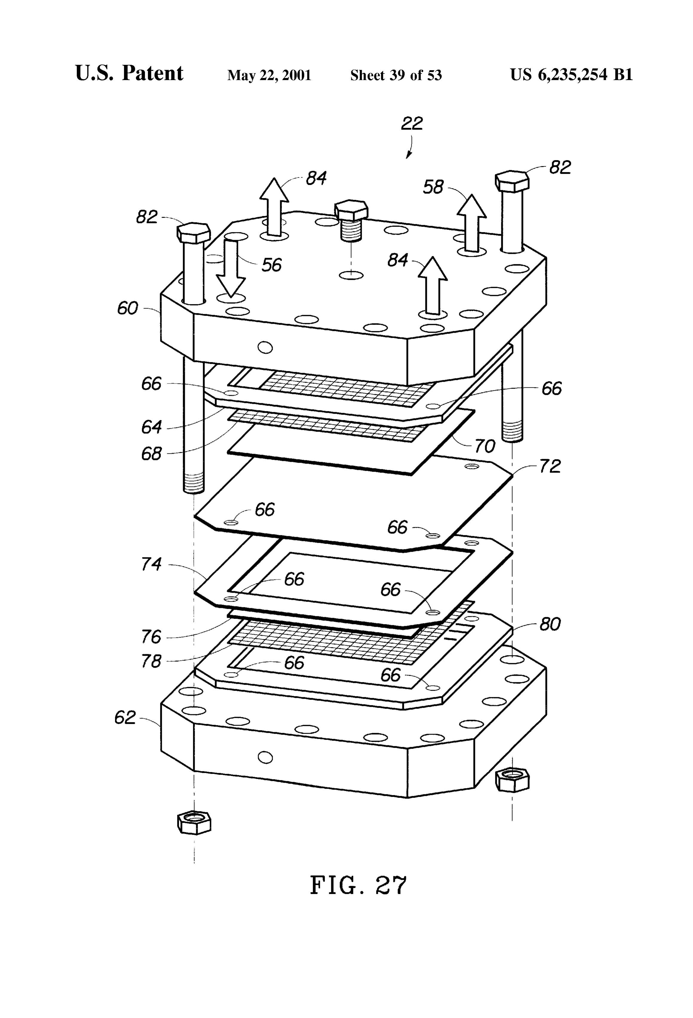
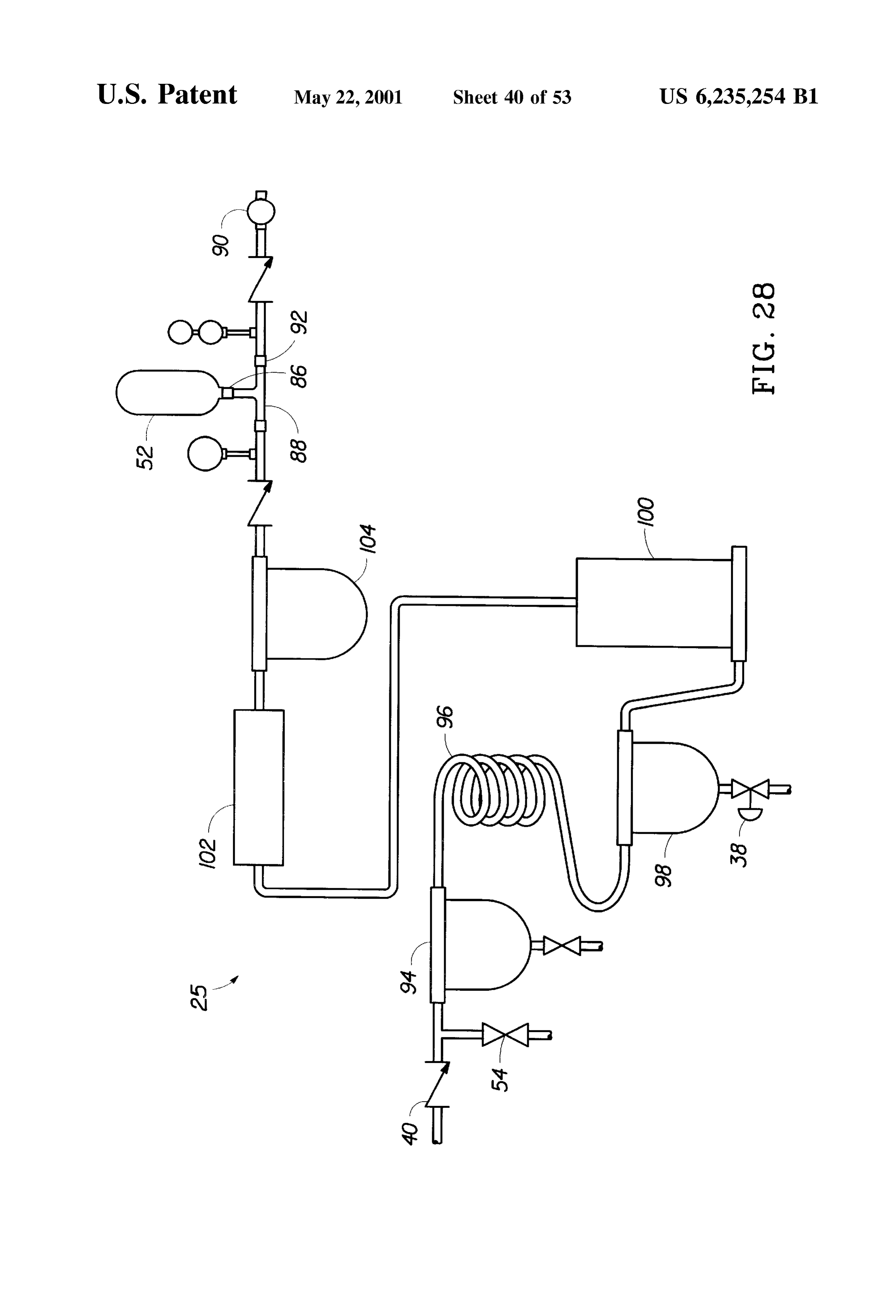
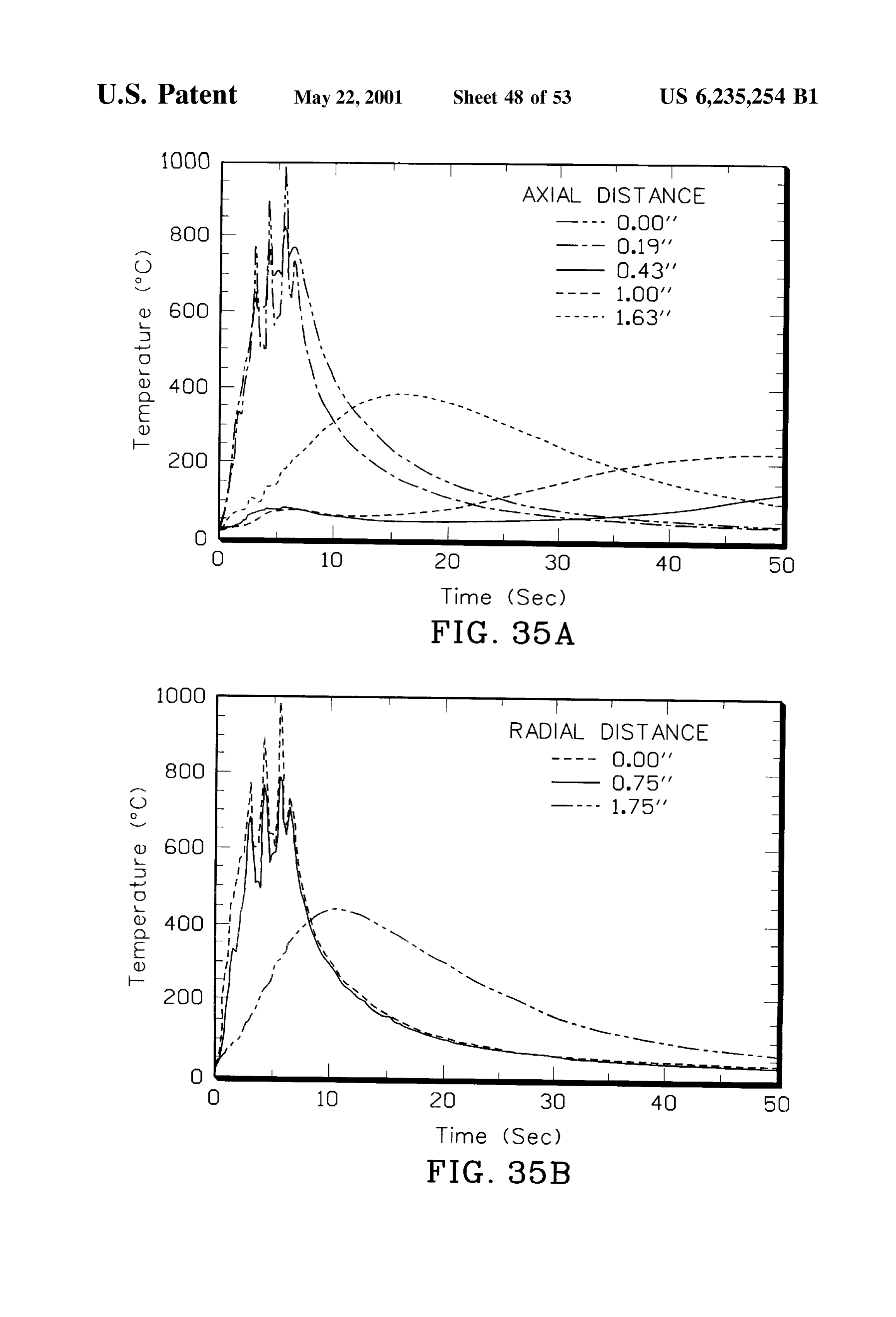
FIG.22 is a graph of catalyst temperature over time with or thermally conditioning a catalyst in accordance with the introduction of ethanol at various flow rates and air into the invention rapidly brings the catalyst up to the light off catalytic converter of FIG. 3 preheated at 130 C. temperature for the efficient conversion of pollutant gases, FIG. 23 is a graph of catalyst temperature over time with Such as unacceptable emissions emanating from an internal introduction of diethyl ether at various flow rates and air into combustion engine, into water, carbon dioxide and other acceptable emissions. In particular, the invention provides the catalytic converter of FIG. 3 preheated at 130 C. efficient heating of the catalytic converter despite the poten FIG. 24 is a graph of catalyst temperature over time with tial presence of water on the catalyst during Startup. introduction of methanol and air into the catalytic converter In one aspect of the invention, a novel catalytic converter of FIG. 3 preheated at 25° C., 45° C., 65° C. and 85°C. monolith is provided which includes a porous Substrate, a FIG. 25 is a graph of catalyst temperature over time with porous washcoat and catalyst particles. Unlike highly Sin introduction of methanol at various flow rates and air into tered ceramics or metal, the Substrate of the present inven the catalytic converter of FIG. 3 preheated at 130 C. tion may be provided with sufficient porosity to draw FIG. 26 is a Schematic diagram of a hydrogen production moisture or condensates from the Washcoat layer into the and delivery System of the present invention for heating a 15 Substrate layer. The pores throughout the Substrate, which catalytic converter. may include both nano-pores and micro-pores, provide a FIG. 27 is an exploded view of a preferred electrolyzer reservoir in which water can be stored until the temperature that may be employed in the present invention. of the catalytic converter rises to vaporize and remove the FIG. 28 is a Schematic of an alternate hydrogen Storage rather Water water. vapor preferentially condenses within the pores than the exposed Surfaces of the catalyst particles.
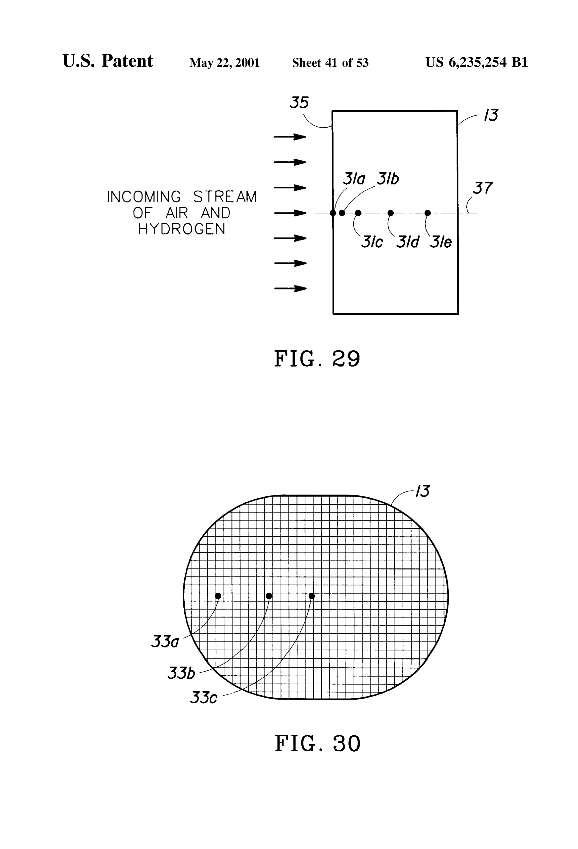
System of the present invention. Therefore, at least a major portion of the catalyst particles FIG. 29 is a cross-sectional side view of a catalytic will remain relatively dry and active for immediate catalytic converter monolith Showing air and hydrogen flow in the oxidation of a fuel that undergoes low temperature catalytic axial direction.
oxidation in the presence of oxygen. The porous Substrate
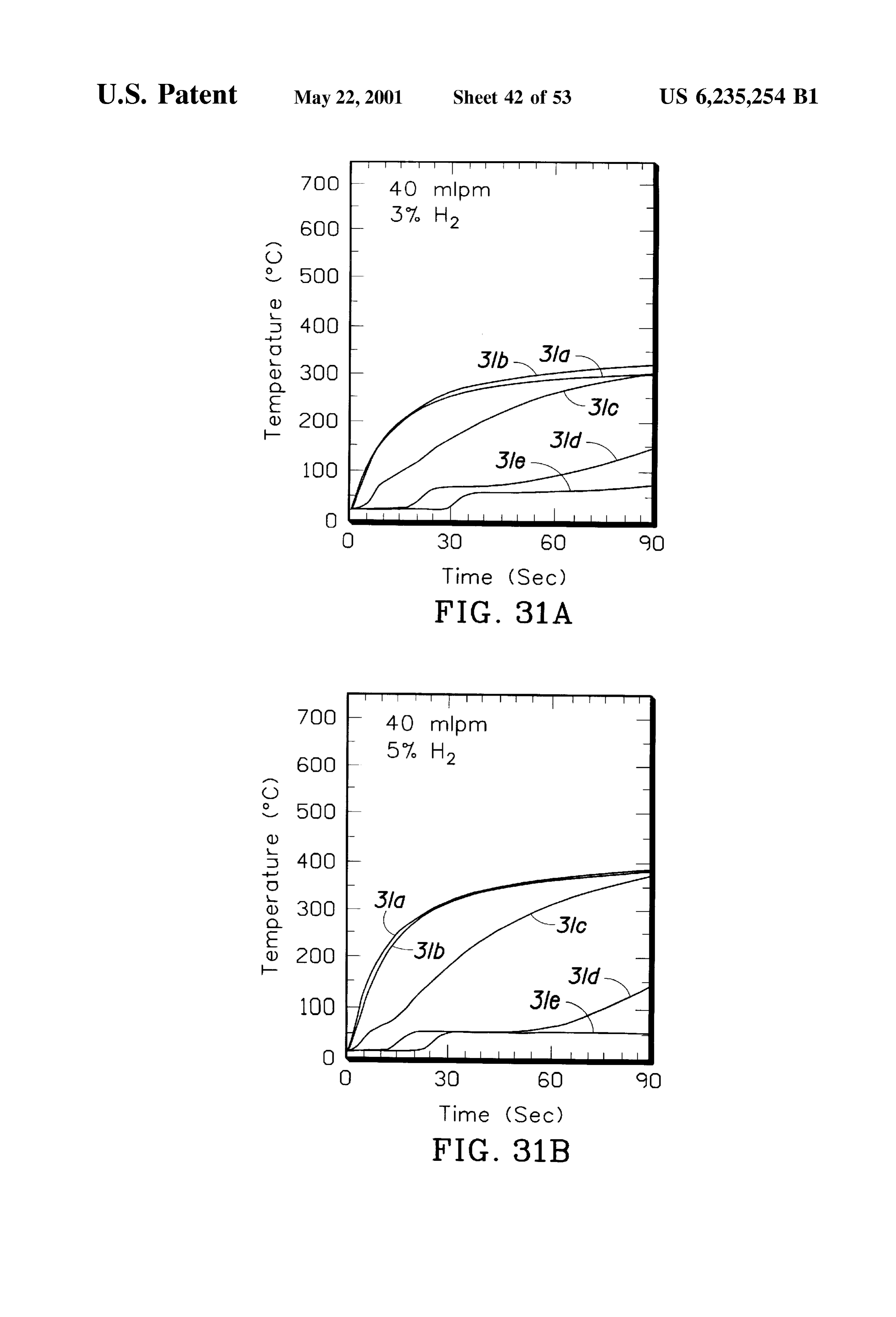
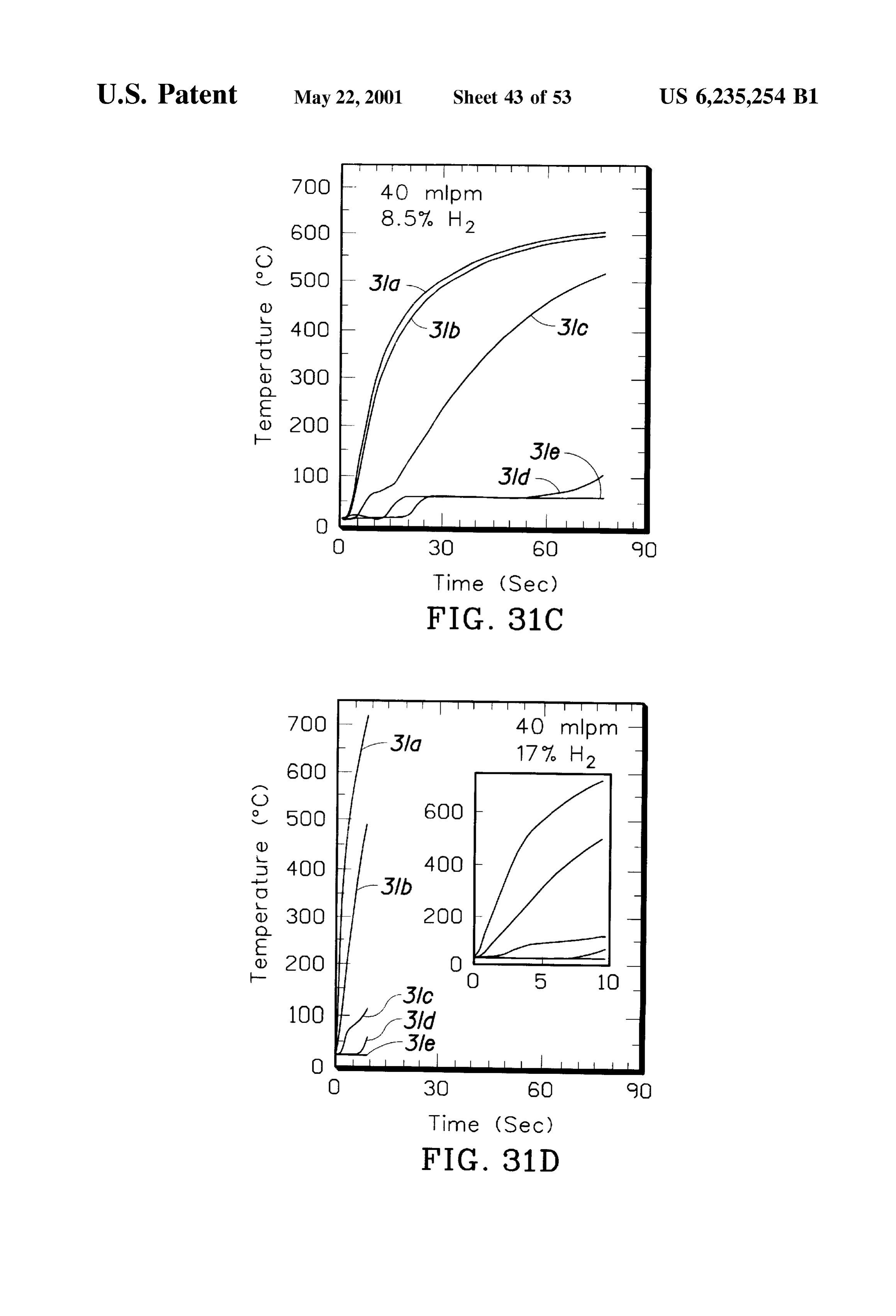
FIG. 30 is a cross-sectional front view of the catalytic 25 may comprise a porous metal or a porous ceramic. converter monolith in FIG. 29; Furthermore, the porous metal may be electrically conduct FIGS. 31(a-d) are graphs of the catalyst temperature ing and perhaps also serve as the element for electrical measured at axial positions within the monolith as indicated heating.
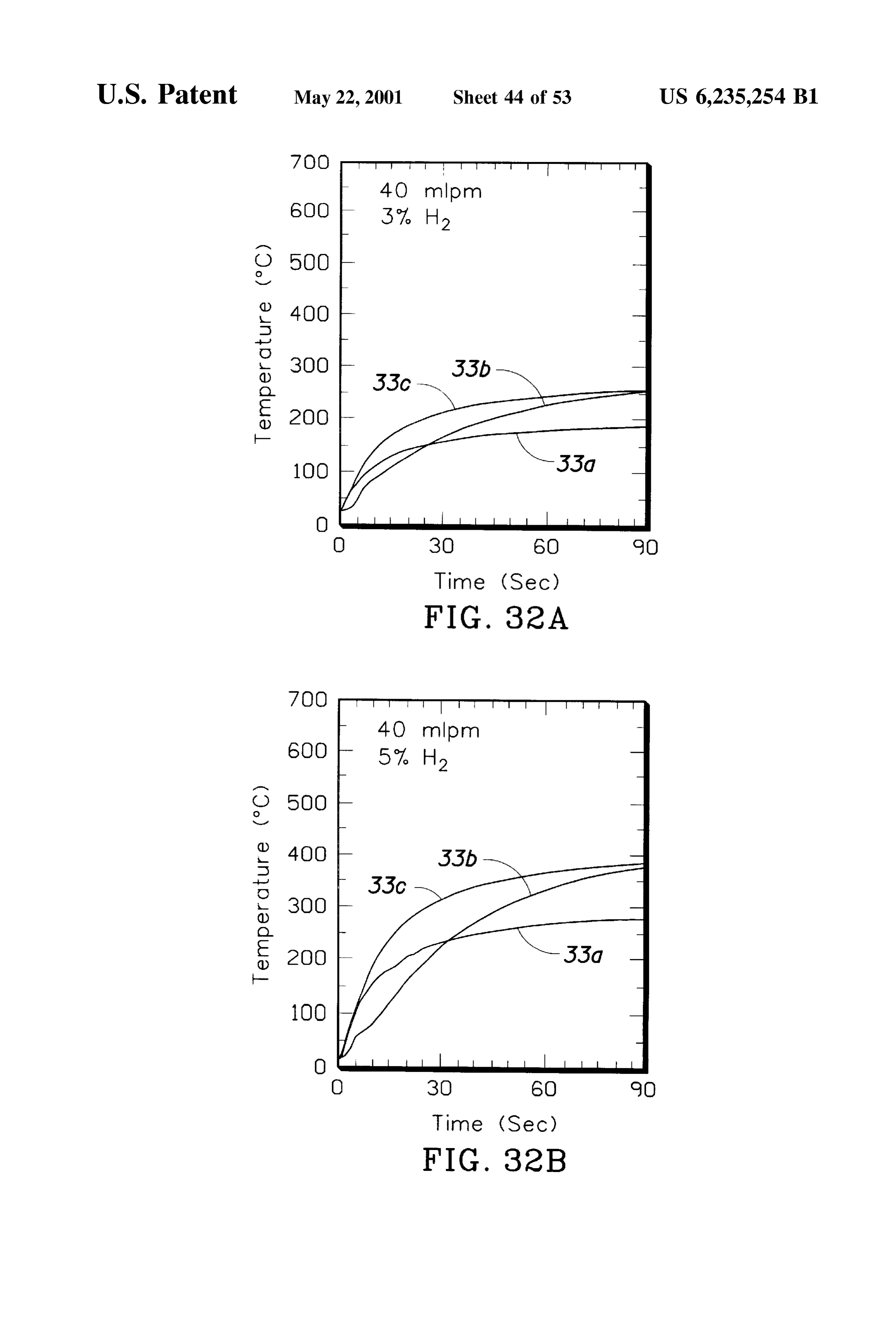
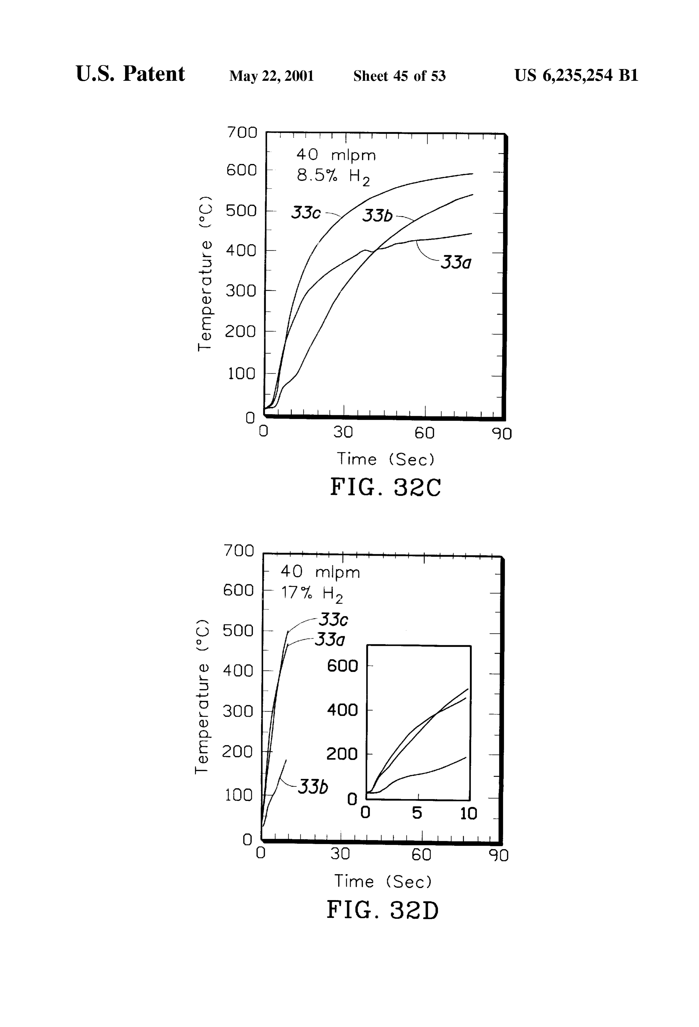
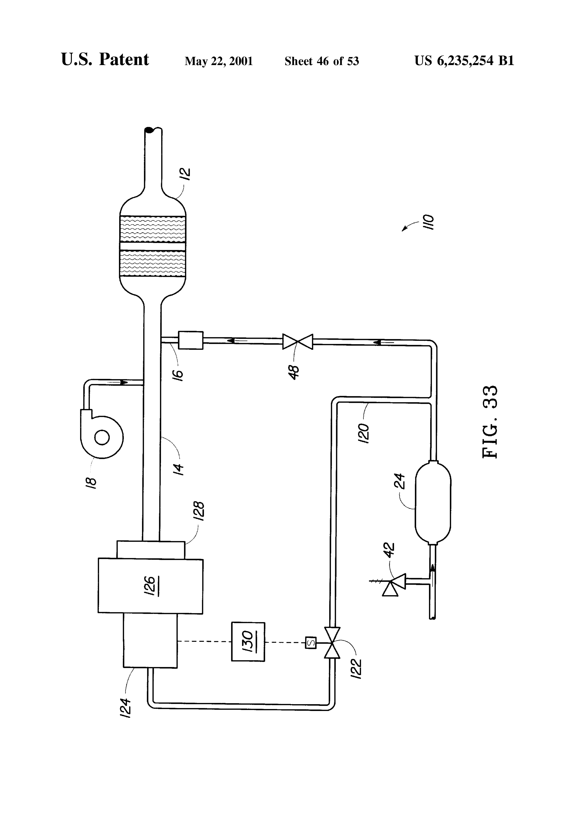
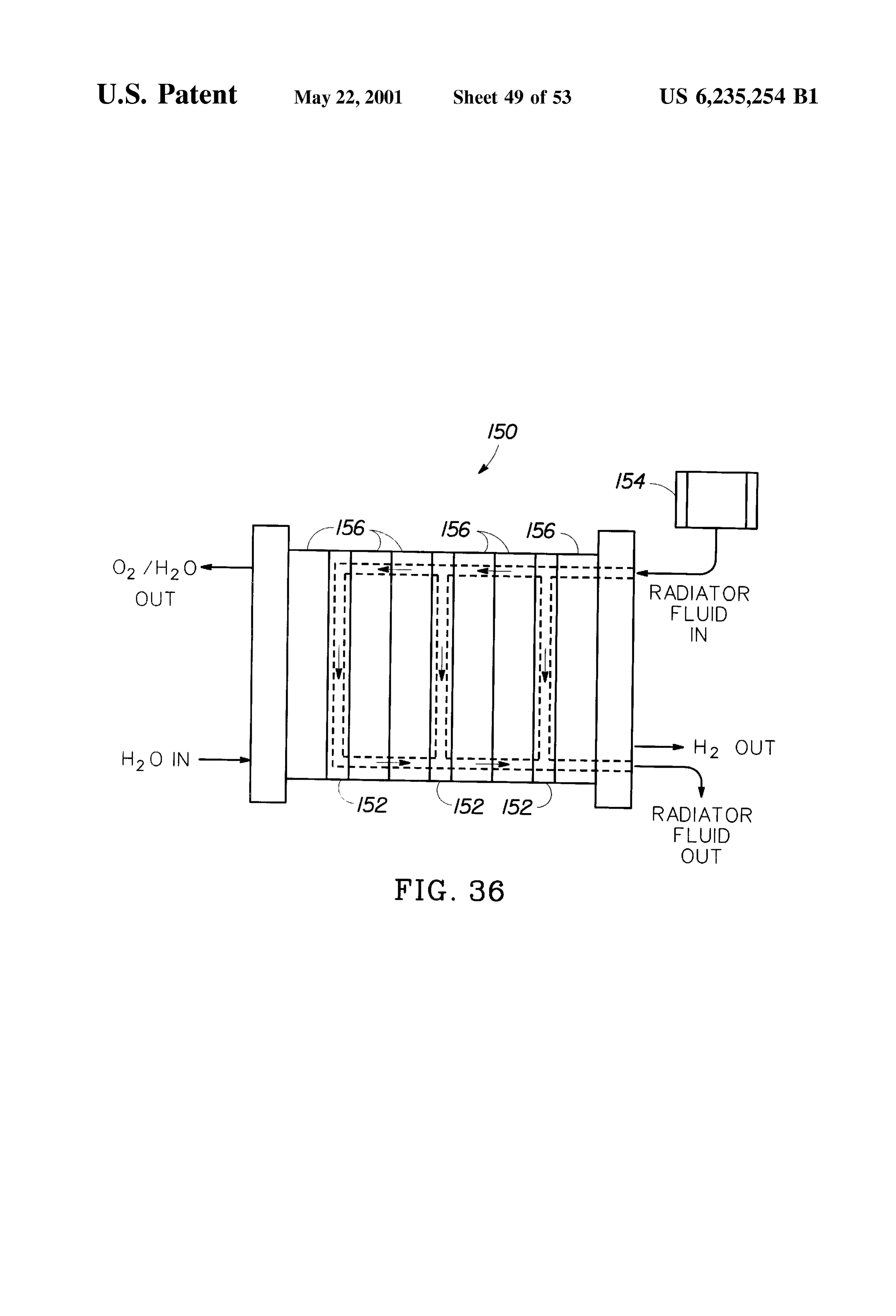
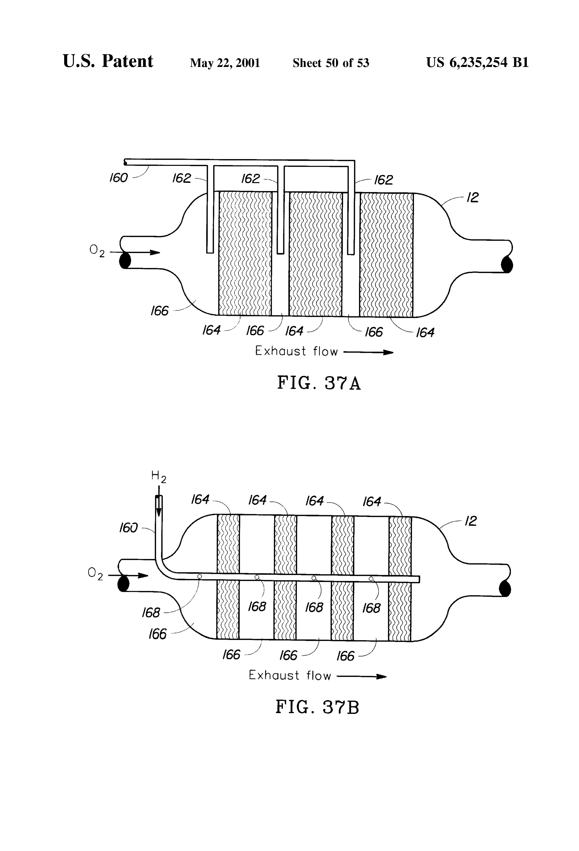
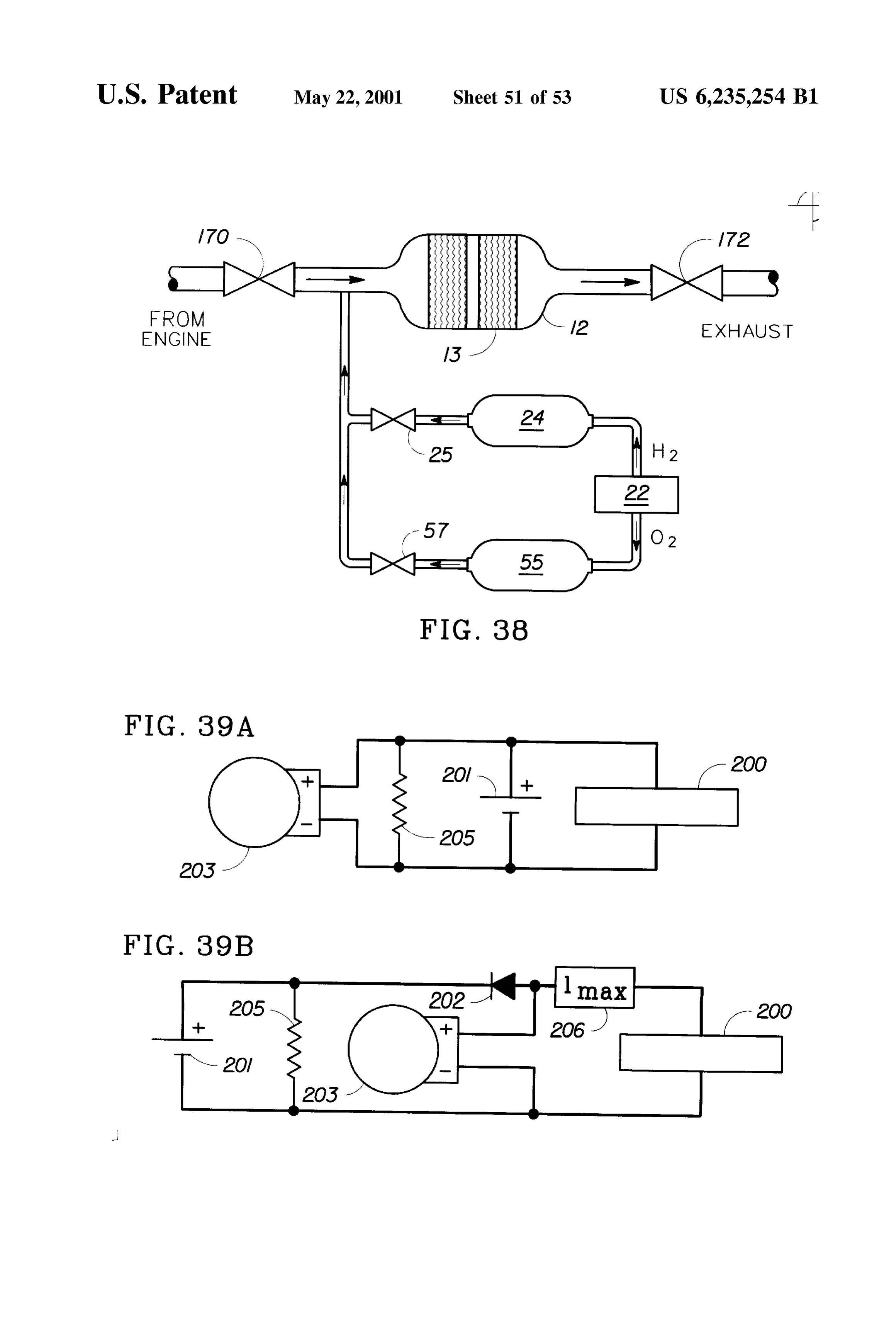
in FIG. 29. In another aspect of the invention, a method is provided FIGS. 32(a-d) are graphs of the catalyst temperature for conditioning a catalyst for catalytic combination of a measured at radial positions within the monolith as indicated pollutant gas, Such as an exhaust gas, with Oxygen. This in FIG. 30. method comprises the Steps of electrically heating a first FIG. 33 is a schematic diagram of a system for the oxygenofandthea catalyst region monolith and catalytically combining fuel that undergoes low temperature catalytic combustion of hydrogen in an internal combustion engine.
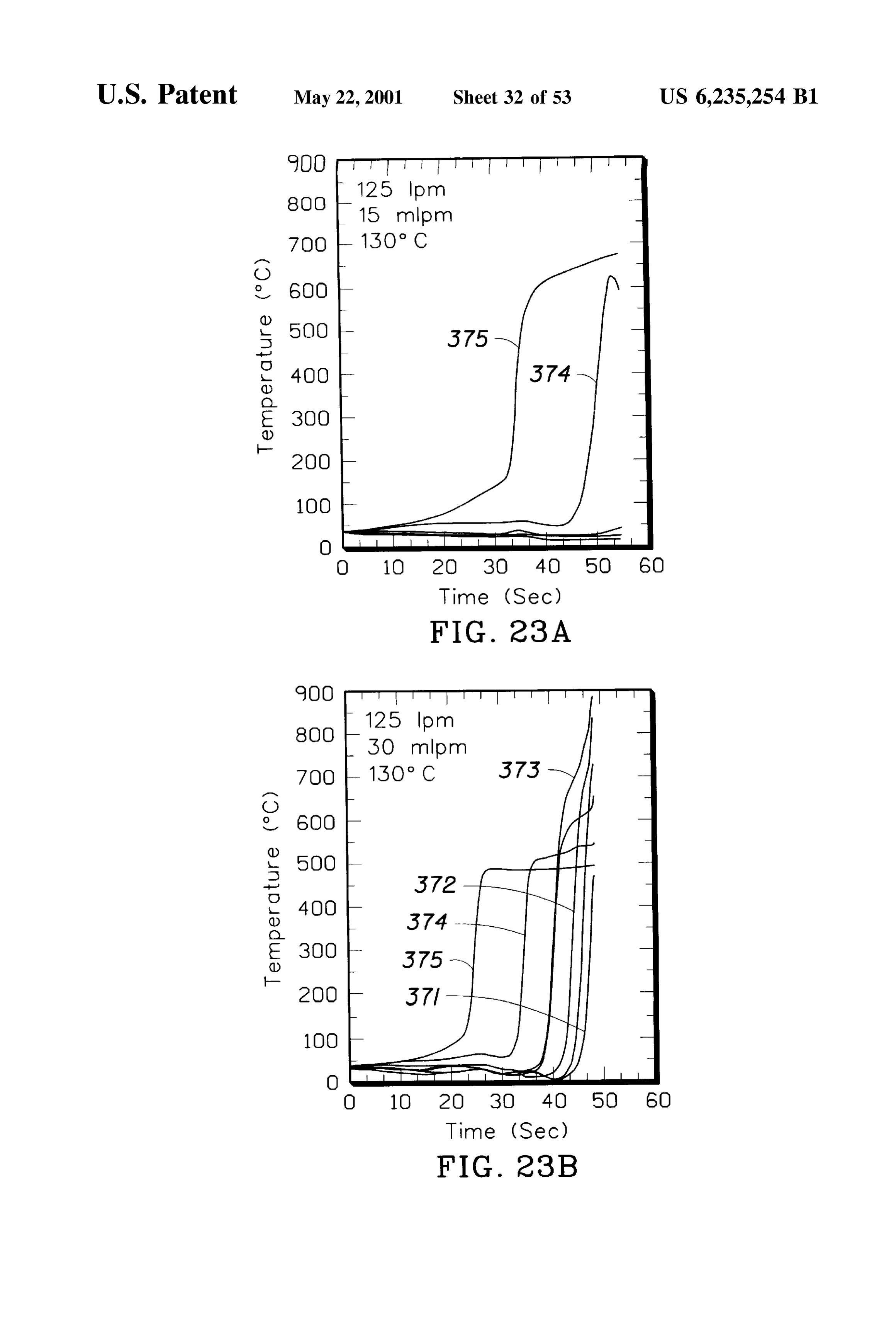
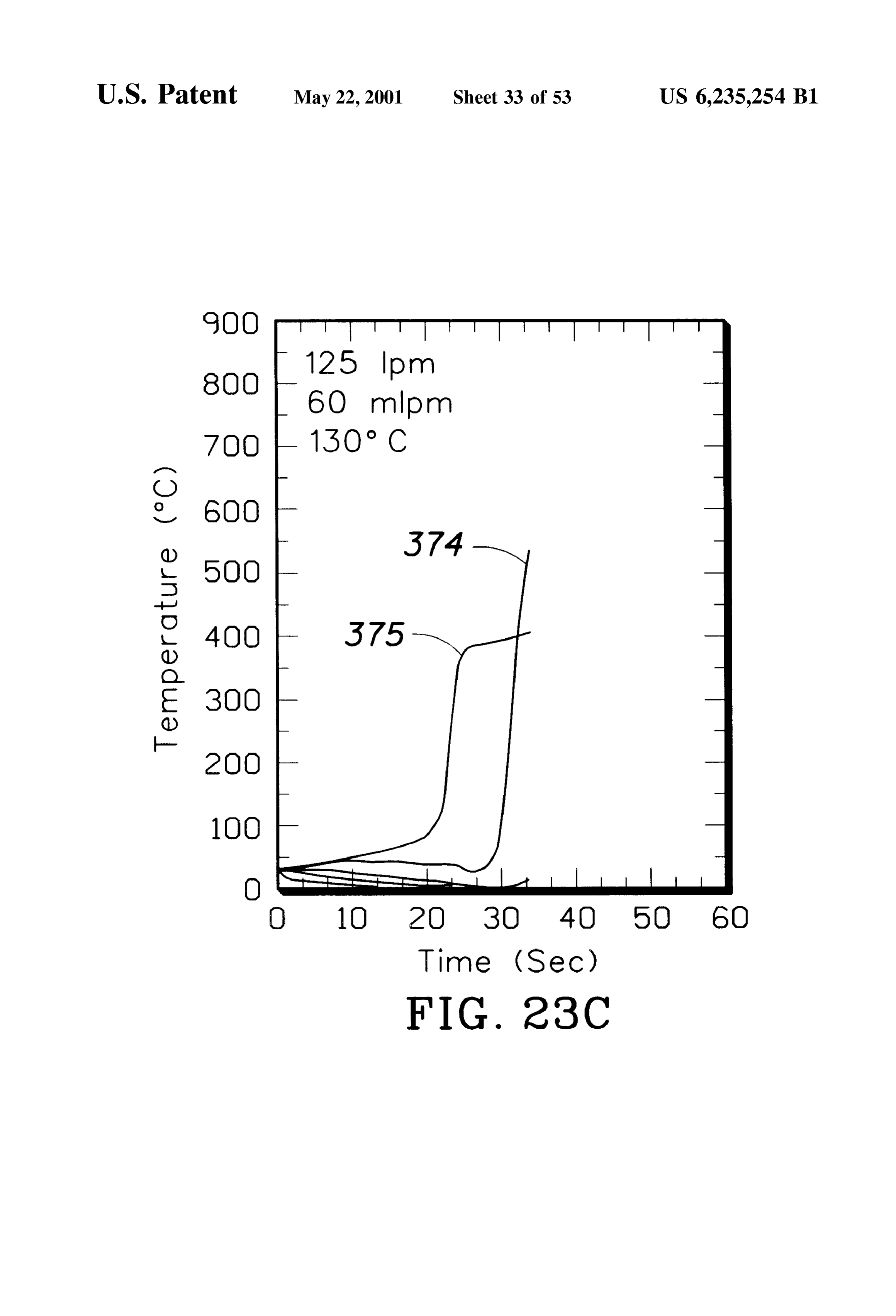
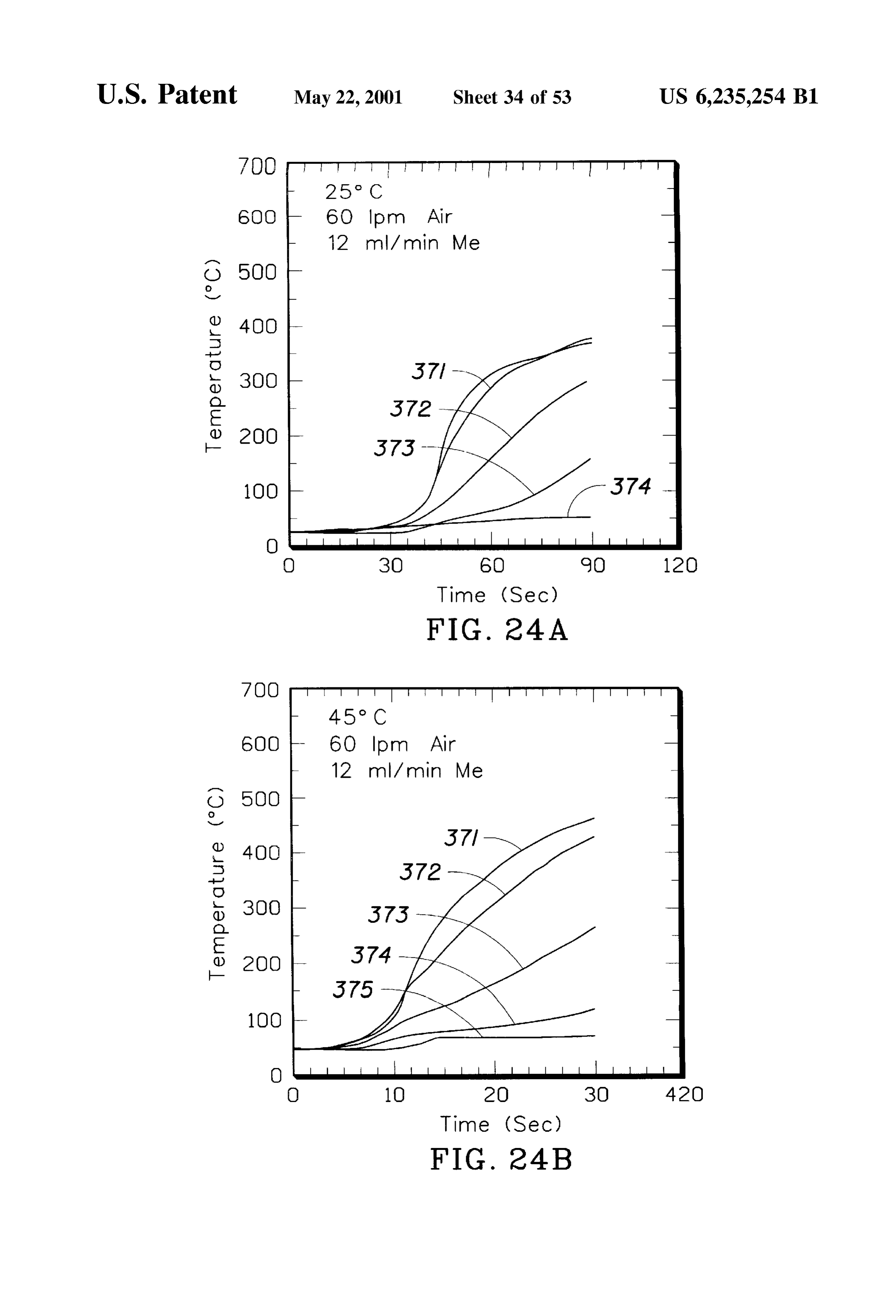
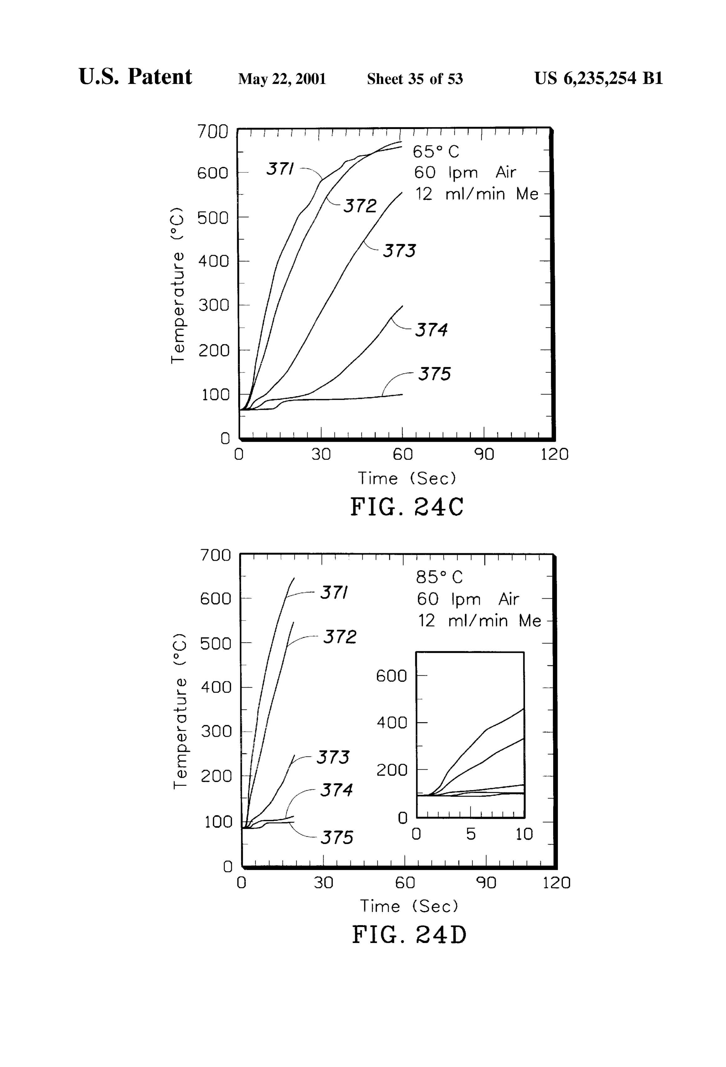
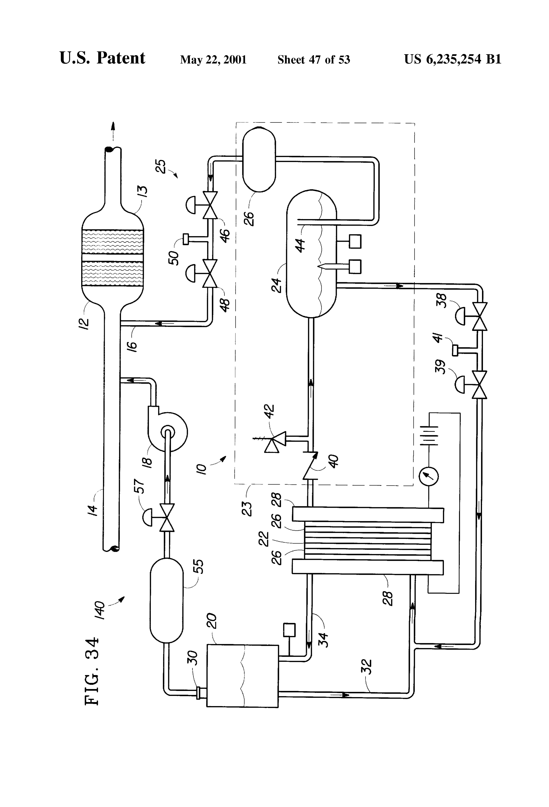
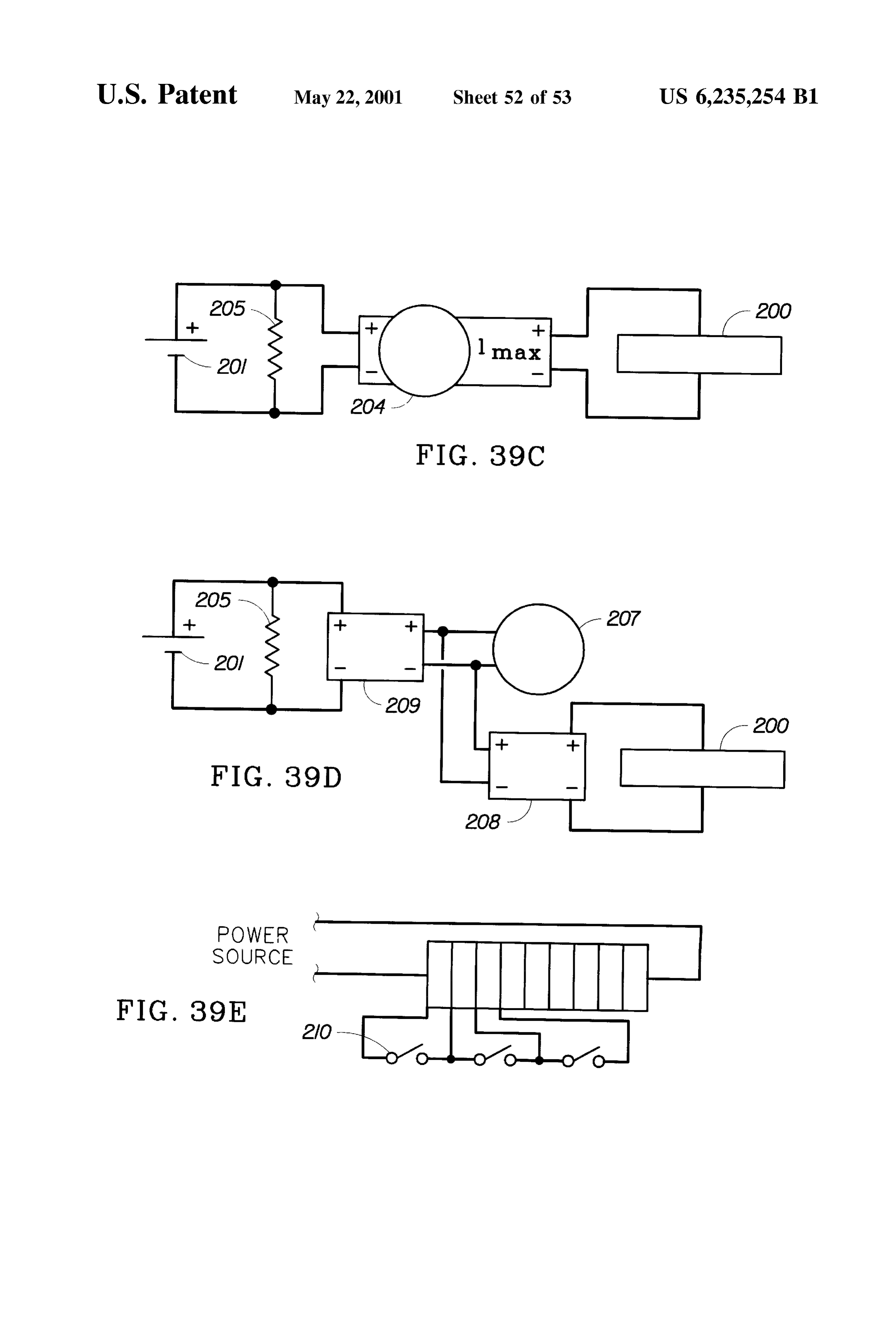
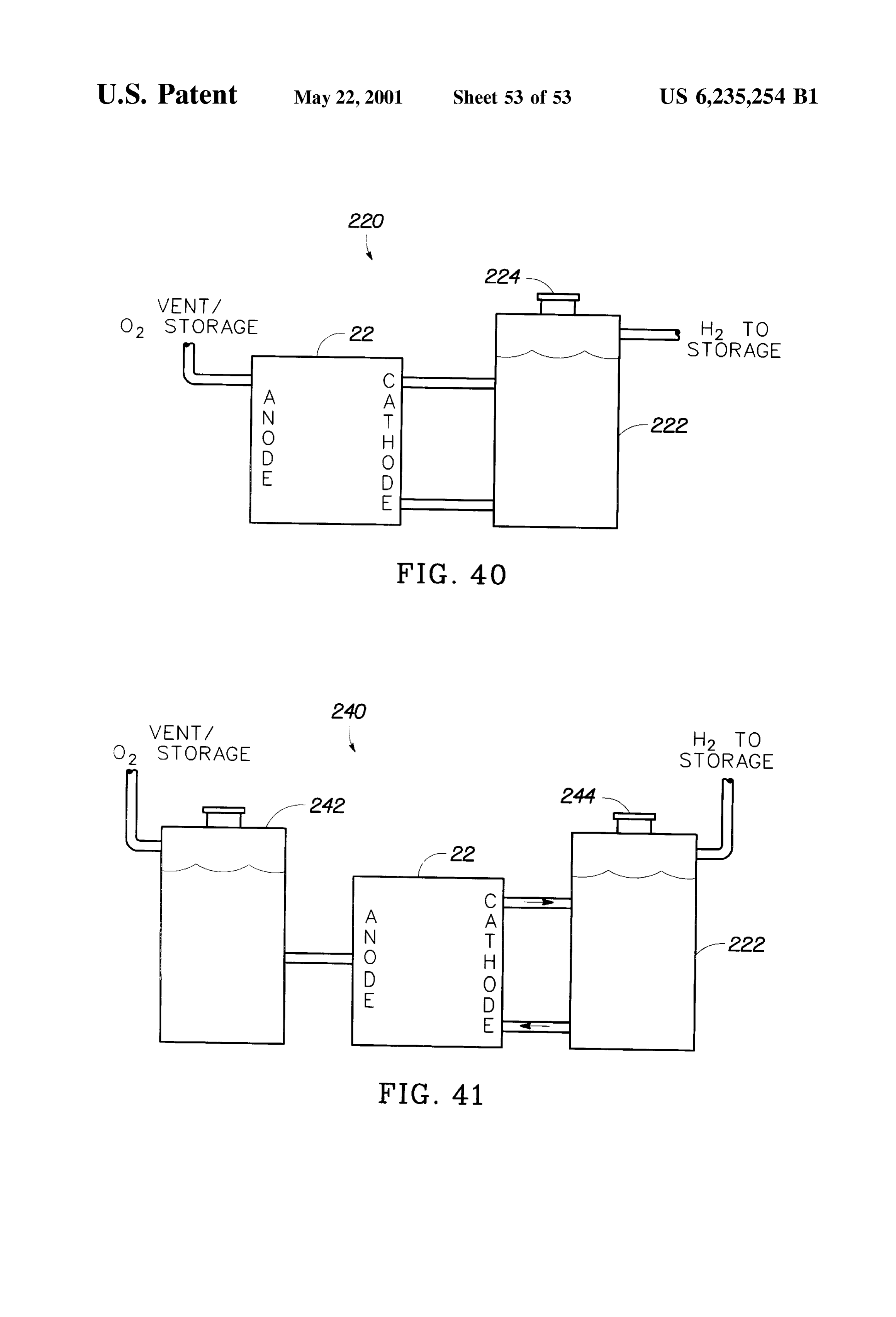
FIG.34 is a Schematic diagram of a System having oxygen 35 oxidation in the catalyst monolith. The electrical heating and recovery and Storage equipment and means for injecting Simultaneously or may catalytic oxidation be performed Simultaneously, Semi in Sequence. Preferably, the electrical oxygen into the catalytic converter. heating renders the first region of the catalyst monolith FIGS. 35(a-b) are graphs of the catalyst temperature at substantially dry. The method may further comprise the step various axial and radial distances in the catalyst monolith 40 of passing an exhaust gas through the catalyst monolith, over a period of 50 Seconds using a pulsed release of either Simultaneous with a portion of one or more of the hydrogen into an air Stream. previous Steps or following completion of the previous FIG. 36 is a Schematic diagram of an electrolyzer having Steps. While the fuels may be organic gases or liquids, the dummy cells for heating or cooling the electrolyzer using preferred fuels are Selected from hydrogen, methanol, liquid from a vehicle radiator. 45 ethanol, dimethoxymethane, trimethoxymethane, FIGS. 37(a-b) are catalyst monoliths having hydrogen methylformate, diethyl ether, and combinations thereof. injection distributors. Both liquid and gaseous fuels are preferably mixed with FIG. 38 is a schematic diagram of a catalytic converter oxygen or air to provide a Substantially homogeneous mix having isolation valves allowing hydrogen or oxygen to ture prior to introducing the fuels to the catalytic converter. diffuse evenly throughout the monolith before delivery of 50 In another aspect of the invention, a plurality of chemical another gas to provide a combustible mixture. heating agents may be used. One preferred method com FIGS. 39(a-e) are schematic diagrams of alternative prises themonolith, Steps of electrically heating a first region of the electrical Systems for providing electrical power to the catalyst fuel that undergoes catalytically combining oxygen and a first low temperature catalytic Oxidation in electrolyzer. 55 the catalyst monolith, and then catalytically combining FIGS. 40 and 41 are schematic diagrams of two alternate oxygen and a Second fuel that undergoes low temperature embodiments of the system of FIG. 26, wherein the water catalytic oxidation in the catalyst monolith. While the first recovery System in the vessel is eliminated. and Second fuels may be in the same phase or different DETAILED DESCRIPTION OF THE phases, it is most preferred that the first fuel undergo 60 catalytic oxidation at a much lower catalytic oxidation
PREFERRED EMBODIMENT
temperature than the Second fuel. A preferred first fuel is
The present invention provides a method and apparatus hydrogen and a preferred second fuel is methanol. While for heating a catalytic converter at least to a light off hydrogen could be used Satisfactorily for the entire chemical temperature. In accordance with the invention, the catalytic heating process, it is impractical to Store Sufficient amounts converter may be heated using a novel monolith 65 of gaseous hydrogen for any significant number of heating construction, electrical heating, catalytic combination of a cycles. Furthermore, the oxygen may be provided to the fuel and oxygen or combinations of these methods. Heating catalyst monolith as air or Stored oxygen in either excess,
Page 60
Stoichiometric, or Sub-Stoichiometric quantities. Again, it is 124 mm and an electrically heated region 304 was provided preferred that the electrical heating render the catalyst with five thermocouples 321,322.323,324.325 located at monolith Substantially dry. distances of about 3 mm, 16 mm, 32 mm, 57 mm and 114 While the present invention includes any combination of mm, respectively, from the front face of the monolith. A electrical and chemical heating, it is beneficial to electrically 5 second having catalyst monolith section 308 includes a member 310 a length of about 46 mm disposed downstream from heat the catalyst monolith to a temperature above about 100 the first catalyst monolith section 302 by a gap 318 of about C., thereby vaporizing water. It may also be beneficial to further heat the catalyst monolith to a temperature above 40 mm and member 312 having a length of about 79 mm about 250 C. Alternatively, electrically heating may be used disposed downstream from the member 310 by gap 314 of about 25 mm. The monolith member 310 was provided with to raise the catalyst monolith to a temperature Sufficiently two thermocouples 326,327 located at distances of about 6 high to provide Substantially complete oxidation of the fuel. and 38 mm from the front face 315. The monolith member The Step of catalytically combining oxygen and the fuel on 312 was provided with a single thermocouple 328 located at the catalyst monolith is preferably continued until the cata a distance of about 38 mm from the front face 317. Both lyst monolith reaches a temperature Sufficiently high to monolith sections 302,308 were wrapped in an insulation provide Substantially complete oxidation of the pollutant 15 and placed inside a glass tube.
gas. To efficiently reach a desired temperature or avoid an undesirably high temperature, the method provides for 330FIG. 2 is a Schematic diagram of an experimental Setup adjusting the flow rate of the fuel or the oxygen. Where the testingdesigned the to simulate a vehicle exhaust system for catalytic converter system 300 of FIG. 1. The fuel is a liquid, the present invention includes introducing Setup included an air blower 332, representative of an engine liquid fuels to the catalyst monolith as a fine mist or spray. exhaust gas flow, communicating through pipe Sections 334 The present invention also provides a method of heating and 301 to the catalytic converter system 300. A flowmeter a catalyst, comprising the Steps of electrically heating a 342 was installed in the pipe section 334. The gases exiting region of the catalyst monolith to a first temperature, and the system 300 were collected by a gas sampling loop 336 then chemically heating the region of the catalyst monolith 25 and delivered to a gas chromatograph 338 having a Suction to a Second temperature greater than the first temperature. It pump 340 coupled to the outlet thereof. is preferred that the Step of chemically heating comprises The setup 330 was also provided with two separate catalytically combining a fuel that undergoes low tempera Subsystems 344, 354 for delivering gaseous and/or liquid ture catalytic oxidation with oxygen in the catalyst monolith. fuels, respectively, that undergo low temperature catalytic Furthermore, the present invention provides a System for oxidation with oxygen in the catalytic converter 300. The heating a catalyst monolith in an exhaust gas line, compris gaseous fuel Subsystem 344 included a hydrogen tank 346 ing an electrical heater in thermal communication with a (with a regulator and control valve), a conduit 348 coupling region of the catalyst monolith, a fuel Source, and a conduit the tank 346 with the pipe 334, and a flowmeter 350 disposed between the fuel Source and the catalyst monolith. disposed in the conduit 348 for monitoring the hydrogen The electrical heater may comprise a Second catalyst mono 35 flow rate. The gaseous fuel Subsystem 344 was also lith having a metal Substrate and may be disposed in the equipped with a mixer, Such as a Static mixer 352, disposed exhaust gas line upstream from the catalyst monolith. The in the pipe 334 to mix the gases before entering the catalytic System preferably includes a flow control member disposed converter 300. The liquid fuel Subsystem 354 included an air in the conduit. One preferred fuel Source is a hydrogen tank 356 (with a regulator and control valve), a conduit 358 generator. The System also preferably includes a Source of 40 coupling the tank 356 with a nozzle 360 upstream of the oxygen, Such as air or an electrolyzer. catalytic converter 300, and a flowmeter 359 for monitoring Finally, the present invention provides a regenerable the air flow rate. The liquid fuel Subsystem 354 also included diesel particulate filter having both electrical and chemical a Syringe pump 362 for metering a liquid fuel, Such as heating as described above. The construction and operation methanol, through a conduit 364 also communicating with of a regenerable diesel particulate filter is disclosed by U.S. the nozzle 360. The simultaneous flow of air and liquid fuel Pat. No. 5,259,190 which is incorporated herein by refer to a suitable nozzle 360 will produce a fine mist or spray of CCC. the fuel to the catalytic converter 300. FIG. 1 is a cross-sectional view of a catalytic converter FIGS. 3(a) and 3(b) are cross-sectional side and face system 300 of the present invention. The system 300 views of an alternative catalytic converter 370 which com includes a pollutant gas passage 301, a first catalyst monolith 50 prises a Single continuous catalyst monolith. For use in section 302 having an electrical heater element 304 near its various experiments, the catalytic converter 370 had a length front face 306, and a second catalyst monolith section 308 of about 53 mm and an oval-like cross-section about 121 disposed downstream from the first section 302. The second mm in width and about 80 mm in height. Again, eight catalyst monolith section 308 may comprise one or more thermocouples were disposed within the monolith 370. Five monolith members, such as monoliths 310 and 312 having 55 thermocouples 371,372.373.374,375 were disposed near the a gap 314 therebetween. The electrical heater element 304 radial center of the monolith 370 at distances of about 0 mm, may be of any known design capable of heating the monolith 5 mm, 11 mm, 22 mm, and 41 mm, respectively. Three section 302, either internal or external, but preferably incor additional thermocouples were disposed at other radial posi porates a resistive metal Substrate having electrical connec tions about 22 mm into the monolith 370. One thermocouple tions 316 for coupling with a power Supply (not shown). A 60 376 was disposed about 19 mm to the side of the thermo catalyst monolith having a resistive metal Substrate Suitable couple 374, a second thermocouple 377 was disposed about for heating the monolith is disclosed in U.S. Pat. No. 19 mm above the thermocouple 374, and a third thermo 4,928,485, which is incorporated by reference herein. couple 378 was disposed about 44 mm to the side of For use in various experiments, the system 300 was thermocouple 374.
equipped with eight thermocouples disposed within the 65 FIG. 4 is a Schematic diagram of a Second experimental catalyst monolith sections 302,308 near the radial center. setup 380 for testing the catalytic converter of FIG. 3. In The first catalyst monolith 302 having a total length of about accordance with setup 380, the air tank 356 (with a regulator
Page 61
and control valve) communicates air through a flowmeter 359, past a heating member 382 to pipe 334. Asyringe pump TABLE 1-continued 362 was used to deliver a liquid organic fuel through a Auto conduit 364 into the pipe 334 where it was mixed with the Melting Boiling ignition air and passed through the mixer 352 before coming into Compounds Point, C. Point, C. Temp, C. contact with the catalytic converter 370. During various
Cyclohexane experiments with setups 330 (of FIG. 2) and 380, the output Cyclohexene 78
from each of the thermocouples was recorded by a data Cycloheptatriene -79.5 116 logger (not shown). Cycloheptene -56 114.7
FIG. 5 is a croSS-Sectional view of a Supported catalyst Cyclopentane -94 SO.1 38O bed 390 in accordance with one aspect of the present Cyclopentene 44 invention. The catalyst bed 390 includes a porous substrate Cyclopropane -128 -33
382, a high surface area, porous washcoat 384 disposed over Cycloheptane O 72.1
the porous substrate 382, and catalyst particles 386 exposed 15 1-Propanol -126 97 413 over the Surface of the washcoat 384. 2-Propanol -89 82
FIG. 6 is a magnified partial cross-sectional view of the tert. Butyl alcohol 25 83 48O supported catalyst bed 390 of FIG. 5 including the porous sec.Butyl alcohol -115 98 ceramic substrate 382, washcoat 384 and catalyst particles Methyl ether -141 -24.8 386. The washcoat may be prepared in any fashion or Diethyl ether -123 35
formula known to those in the art, Such as those washcoats iso-Propyl ether 68 disclosed in U.S. Pat. No. 5,130,109, which is incorporated tert-Amyl ether 85 herein by reference. Accordingly, the catalyst particles 386 Butyl ethyl ether -124 91 may be applied over the washcoat or disposed throughout tert-Butyl ether -97 72 the Washcoat So long as catalyst particles have Surfaces that 25 Methano
Ethanol
are exposed. The washcoat 384 includes pores 388 that 1,1-Dimethoxyethane 64 provide a pathway from the top surface of the washcoat 384 Acetaldehyde -125 21 to the pores 392 of the porous substrate 382. The pores 388 Dimethoxymethane -105 41 and 392 are preferably sized to draw moisture away from the Diethoxymethane
catalyst particles of the washcoat layer 384 and into the 1,2-Diethoxyethane -74 121 pores of the substrate 382, thereby maintaining the catalyst Methyl formate -99.8 31.5 456 in a relatively dry condition. The pores may include both Bis(2-Methoxyethyl) ether -68 161 nano-pores and micro-pores.
Fuels Suitable for use in accordance with the present EXAMPLE if1 invention are listed in Table 1 below. 35
The experimental setup 330 of FIG. 2 was used for the
TABLE 1. introduction of hydrogen and air to a Substantially dry catalytic converter 300. The blower 332 provided air
Melting Boiling
Auto ignition through the catalytic converter 300 at a rate of about 325
40 liters per minute (lpm). Heating of the catalytic converter was tested at 6 volume percent (vol%), 7 vol% and 8 vol
Methane -182.4 -161.5 537 % hydrogen in air. FIGS. 7(a-c) are graphs showing the Ethane -182.8 88.6 results of catalyst temperature over time with introduction of
Butane -138.4 -0.5 287 hydrogen and air.
Pentane -129.7 36.1 309 45
EXAMPLE if?
Hexane
Heptane
The experimental setup 330 of FIG. 2 was used for the
Octane -56.8 125.6 2O6.1 introduction of hydrogen and air to a wet catalytic converter Acetylene -84. -80.8 298 300. About 2 milliliters per minute of water was applied to Ethylene -169.0 -103.7 449 50 the converter 300 at room temperature over a period of about
10 minutes through the liquid injection Subsystem and (trans) 2-Butene -105.5 O.8 323 allowed to Soak for a period of about 10 minutes to simulate (cis) 2-Butene -138.9 3.7 323 water that condenses in an automotive catalytic converter as 1-Pentene -165.2 29.9 273 the system cools. The blower 332 then provided air through (trans) 2-Pentene -140.2 36.3 55 the catalytic converter 300 at a rate of about 325 liters per (cis) 2-Pentene -151.4 36.9 minute (lpm) with about 6 vol% hydrogen. FIGS. 8(a-d) are
1-Hexene -139.7 63.4 265 graphs of the catalyst temperature over time with introduc (trans) 2-Hexene -133. 67.9 244 tion of hydrogen and air to a wet catalyst along with no (cis) 2-Hexene -141.1 68.8 electrical heating, electrical heating from room temperature (tran) 3-Hexene -115.4 67.1 60 to 50° C., electrical heating from room temperature to 100
1-Heptene -119.7 93.6 262 C., electrical heating from room temperature to 150 C. (tran) 2-Heptene -109.5 98.1 In the graphs, the temperature profile given by each (cis) 2-Heptene 98.4 thermocouple is labeled by the corresponding reference
(cis) 3-Heptene 95.7 number of FIG.1. Also, the point at which the thermocouple Tetrahydrofuran -106 65 65 322 within the electrically heated region 304 reached a Dioxane 11.8 101 18O termination temperature, thereby shutting off the electrical heating, is indicated by the letters “EHC'.
Page 62
Note that in FIG. 8(a), the thermocouples 321,322 in the front region of the catalytic converter, represented by ther front of the monolith are initially cooler than thermocouples mocouples 321 and 322, achieved a temperature of 700 C. 323,324 which are somewhat further into the monolith. As within a period of only 4 Seconds. This performance is electrical heating is used to greater and greater temperatures, roughly the same as the performance under Example 5 at an the thermocouple 322 records the greater temperature initial catalyst temperature of 200 C. increases. However, under each of the four conditions, the front thermocouple 321 eventually reached the highest tem EXAMPLE if7 perature due to chemical heating after the catalyst was warm The experimental setup 330 of FIG. 2 was used for and dry. It is also apparent from FIGS. 8(a-d) that electrical transient heating of the catalytic converter 300 first using heating was beneficial for rapidly heating the catalyst, electrical heating to a Set point temperature, then introducing especially to temperatures of about 100° C. or higher for the 50 mlpm methanol and air to the catalytic converter 300. The evaporation of water. blower 332 provided air through the catalytic converter 300 EXAMPLE if3 at a rate of about 325 liters per minute (lpm) throughout the experiment. FIGS. 13(a-d) are graphs of catalyst tempera 15 ture over time with electrical heating up to a Set point
The experimental setup 330 of FIG. 2 was used for the introduction of methanol and air to the catalytic converter temperature of 250° C., 300° C., 350° C. and 400° C., 300. The blower 332 then provided air through the catalytic respectively, before introducing the methanol. From these converter 300 at a rate of about 325 liters per minute (pm) Figures, it is apparent that chemical heating with methanol for a Sufficient period of time to achieve a steady State is capable of heating the catalyst much more rapidly, as temperature of 100° C. throughout the entire catalytic con evidenced by the increased slope of the temperature profiles verter. FIGS. 9(a-d) are graphs of the catalyst temperature both electrical heating and introduction of methanol and air. over time with introduction of methanol at flow rates of 20 Furthermore, delaying the introduction of methanol in favor milliliters per minute (mlpm), 30 mlpm, 40 mlpm and 50 of additional electrical heating was shown to delay attaining mlpm, respectively. The front thermocouple 321 is initially 25 a catalyst temperature of 700 C. cooled by the flow of methanol and air. It is also apparent EXAMPLE is that the higher methanol flow rates provides more rapid heating. Using the data from Examples 3-6, it was possible to calculate a methanol conversion factor that represents the
EXAMPLE if4 efficiency with which methanol was reacted to produce heat. The procedure of Example 3 was repeated, but at an initial FIG. 14 is a graph of methanol conversion factor as a steady state temperature of 150° C. FIGS. 10(a-d) are function of the catalyst monolith Steady State temperature between 150° C. and 250° C. for methanol flow rates of 30 graphs of catalyst temperature over time with introduction of mlpm and 50 mlpm. At the lower temperatures of 150-200 methanol at flow rates of 20 milliliters per minute (mlpm), C., the lower flow rate of methanol was more efficiently 30 mlpm, 40 mlpm and 50 mlpm, respectively. Comparing 35 utilized. However, at catalyst temperatures of 200-250 C., FIGS. 10(a-d) with FIGS. 9(a-d), it is shown that a higher the conversion efficiency at the two flow were roughly the initial catalyst temperature allows the chemical heating to SC.
proceed at a much faster rate than at low initial catalyst FIG. 15 is a graph of the chemical energy required and the temperatures.
40 time to reach 400 C. in a catalyst monolith preheated
EXAMPLE is electrically under steady state conditions to 100° C., 150 C.,
The procedure of Example 3 was again repeated, but at an FIGS. 16 and 17 each show two bar charts illustrating the initial steady state temperature of 200 C. and an air flow time and energy required for the catalyst to reach 400° C. as rate of 350 lpm. FIGS. 11(a-d) are graphs of catalyst 45 a function of the catalyst temperature at which methanol temperature over time with introduction of methanol at flow injection was commenced. FIGS. 16(a-b) includes data rates of 20 milliliters per minute (mlpm), 30 mlpm, 40 mlpm collected using 50 mlpm methanol. FIG. 16(a) shows that and 50 mlpm, respectively. Comparing FIGS. 11(a-d) with the shortest time period for achieving 400° C. was 7 seconds. FIGS. 10(a-d), it is again shown that a higher initial catalystThis rapid heating was performed by using electrical heating temperature allows the chemical heating to proceed at a 50 to 150° C., but roughly similar rapid heating was achieve by much faster rate than at low initial catalyst temperatures. AS electrical heating to 200° C. FIG.16(b) shows that the least shown in FIG. 11(d), the front region of the catalytic amount of energy required to reach 400° C. was achieved converter, represented by thermocouples 321 and 322, with electrical heating up to 200 C., but this was only achieved a temperature of 700 C. within a period of only 4 marginally better than electrical heating up to 150 C. Note Seconds. that FIG. 16(b) also shows that rapid heating requires more
EXAMPLE if6 chemical energy than electrical energy.
FIGS. 17(a-b) show somewhat similar results using 30
The procedure of Example 3 was once again repeated, but mlpm methanol. However, comparing FIGS. 17(a-b) with at an initial steady state temperature of 250 C. and an air FIGS. 16(a-b) it is shown that if lower flow rates of flow rate of 350 lpm. FIGS. 12(a-d) are graphs of catalyst 60 methanol were used, it was favorable to use more electrical temperature over time with introduction of methanol at flow heating. For example, it appears that at 30 mlpm methanol, rates of 20 milliliters per minute (mlpm), 30 mlpm, 40 mlpm electrical heating to 250 C. provided perhaps the most rapid and 50 mlpm, respectively. Comparing FIGS. 12(a-d) with heating.
FIGS. 11(a-d), it is once again shown that a higher initial EXAMPLE iO catalyst temperature allows the chemical heating to proceed 65 at a faster rate than at low initial catalyst temperatures, but The experimental setup 380 of FIG. 4 was used to provide there are diminishing returns. As shown in FIG. 12(d), the a flow of air at 130 lpm and a steady State temperature of
Page 63
130° C. FIGS. 18(a-d) and 19(a-c) are graphs of catalyst the previous heating mode. Most preferably, combinations temperature over time with introduction of tri of heating modes should be chosen which collectively methoxymethane at flow rates of 20 mlpm, 24 mlpm, 28 provide effective operation, i.e., high rate of temperature mlpm, 32 mlpm, 26 mlpm, 40 mlpm and 44 mlpm, respec increase and efficient conversion of energy, over the desired tively. While heating was again more rapid with greater range of temperatures. However, it should also be recog amounts of fuel (trimethoxymnethane), if the desired tem nized that the Selection of heating modes may involve a perature is, for example, 700 C., then more than about tradeoff between rate of heating and efficiency. Furthermore, 28-32 mlpm trimethoxymethane results in little, if any, other practical considerations should be considered, Such as benefit. available Storage quantities, ability to regenerate, battery life, operational Safety and the like.
EXAMPLE if 10 In various examples above, electrical heating was used in combination with chemical heating using hydrogen or
The experimental setup 380 of FIG. 4 was used to provide methanol. However, the present invention Specifically a flow of air at 125 lpm and an initial Steady State tempera anticipates the use of even three or more heating modes, ture of 130° C. FIGS. 200a-d) are graphs of catalyst tem 15 where the use of different chemicals is considered to be a perature over time with introduction of dimethoxymethane Separate mode. For example, it is believed that the Sequential at flow rates of 20 mlpm, 25 mlpm, 30 mlpm, and 35 mlpm, use of electrical heating, hydrogen oxidation, and methanol respectively. oxidation would provide an effective System. Electrical heating is largely unaffected by water on the catalyst and can
EXAMPLE if 11 rapidly bring the catalyst to a temperature above 100 C. or more. Gaseous hydrogen undergoes catalytic oxidation with
The experimental setup 380 of FIG. 4 was used to provide air at low temperatures, even temperatures below 100 C., a flow of air at 125 lpm and a steady State temperature of and, optionally, can be regenerated. Methanol is a liquid at 130° C. FIGS. 21(a-d) are graphs of catalyst temperature ambient temperatures, allowing more efficient Storage than over time with introduction of methyl formate at flow rates hydrogen, and undergoes catalytic oxidation with air at of 25 mlpm, 35 mlpm, 45 mlpm, and 55 mlpm, respectively. 25 temperatures rapidly achievable by hydrogen oxidation. Collectively, this System would provide rapid heating and
EXAMPLE if12 efficient energy conversion.
FIG. 26 is a schematic flow diagram of a system 10, for
The experimental setup 380 of FIG. 4 was used to provide use in accordance with one embodiment of the present a flow of air at 125 lpm and a steady State temperature of invention, installed on a vehicle to deliver hydrogen to the 130° C. FIGS. 22(a-d) are graphs of catalyst temperature exhaust System. The vehicle includes a catalytic converter over time with introduction of ethanol at flow rates of 15 12 located in an exhaust line 14 from a vehicle's exhaust mlpm, 30 mlpm, 60 mlpm, and 75 mlpm, respectively. manifold, as shown. The exhaust line 14 is provided with EXAMPLE if13 hydrogen from a hydrogen inlet line 16 and, preferably, air 35 from an air pump 18. The air pump could be any Suitable air
The experimental setup 380 of FIG. 4 was used to provide Source for injecting air into the exhaust line at Suitable a flow of air at 125 lpm and a steady State temperature of preSSure and Volumetric flow rate to achieve any desired 130° C. FIGS. 23(a-c) are graphs of catalyst temperature air/hydrogen ratio mixture. The air pump may be replaced over time with introduction of diethyl ether at flow rates of by a Venturi wherein the pressurized hydrogen gas provides 15 mlpm, 30 mlpm, and 60 mlpm, respectively. 40 a motive force Sufficient to draw in ambient air. The system 10 includes a water reservoir 20, an electro
EXAMPLE if14 lyZer 22, a hydrogen Storage vessel 24 and a hydrogen The experimental setup 380 of FIG. 4 was used to provide delivery system 25. The electrolyzer 22 may preferably a flow of air at 60 lpm. FIGS. 24(a-d) are graphs of catalyst 45 end platesa28.
comprise plurality of Stacked identical cells 26 between temperature over time with introduction of methanol and air only as a waterThe water reservoir 20 preferably serves not Storage chamber but also as a separator for into an electrically preheated catalytic converter at 25 C., oxygen gas and water and means of dissipating heat. The 45 C., 65 C. and 85 C., respectively. Show a dramatic reservoir 20 may be a vehicle's reduction in heating time with increasing preheated catalytic Storage container, but is preferablywindshield washer fluid a dedicated reservoir/ converter temperature. 50 Separator, optionally allowing collection and Storage of EXAMPLEif15 oxygen via port 30. Water flows by gravity drain or is pumped from the reservoir 20 to the anodes of the electro
The experimental setup 380 of FIG. 4 was used to provide lyZer 22 via a Supply line 32. AS the anodes produce oxygen, a flow of air at 601 pm and an electrically preheated catalyst the oxygen and entrained water rises naturally back to the at 130° C. FIGS. 25(a-d) are graphs of catalyst temperature 55 reservoir 20 via a return line 34. over time with introduction of methanol at flow rates of 15 The system also provides for the use of a low carbon mlpm, 20 mlpm, 25 mlpm and 30 mlpm, respectively. containing alcohol, e.g., methanol, ethanol or propanol, in In accordance with the present invention, various combi the water throughout the System in order to depress the nations of the heating modes described above may be used freezing point of the water. An alcohol, Such as methanol, Simultaneously, Sequentially, periodically or overlapping 60 may be provided in any useful concentration, but preferably with each other. However, it is generally preferred that the at an alcohol water molar ratio of between Zero and about first heating method be efficient at ambient temperatures and 1:1. The alcohol is carried with the water throughout the wet conditions. Any Subsequent heating mode will prefer System and may be oxidized at the anode to carbon dioxide ably be efficient attemperatures and conditions prevailing at gas (CO2), six hydrogen ions (H), and six electrons (e'). the point of initiating the Subsequent heating mode. AS 65 The hydrogen ions, or protons, and electrons are recombined mentioned above, these Subsequent heating modes may be at the cathode to form three molecules of molecular hydro initiated before, Simultaneous with, or after termination of gen (H2).
Page 64
A bubble detector 37 is preferably disposed adjacent or the reservoir 222 could be filled using pressurized water, around the return line 34 in order to Sense the passage of gas which would allow manufacturing control over filling if the bubbles therein. A suitable type of bubble detector is an System requires Specialized equipment. optical transmission type detector. The electronic Signal To eliminate the complexity and Safety issues involved, from the bubble detector 37 is preferably transmitted to a the system 240 shown in FIG. 41 uses an anode reservoir controller 134 and the Signal indicates that at least certain 242 and a cathode reservoir 244. This system 240 still aspects of the electrolyzer 22 are operating properly. utilizes osmotic movement of the water from the cathode to Conversely, if the Signal indicates the absence of gas bubbles the anode in normal operating mode but new water is in the return line 34, then the electrolyzer 22 may have a provided at the anode (at ambient pressure) and this water is problem, Such as a ruptured proton eXchange membrane transferred to the cathode Via electroosmosis during the (PEM), depleted or blocked water supply, etc. Furthermore, initial operation of the electrolyzer 22 after filling the anode the controller 134 receiving the signal from the bubble reservoir 242. Once all the anode water is depleted, elec detector 37 may analyze the number of gas bubbles passing troosmosis between the reservoirs 242,244 ceases and, once through the line 34 over a period of time as Some indication again, all process water is provided through the cathode. of the electrolyzer's operating efficiency. 15 Referring back to FIG. 26, the hydrogen is delivered out The hydrogen produced at the cathodes of the electrolyzer of the Storage vessel 24, preferably through a Standpipe 44, 22 is delivered under pressure to a hydrogen Storage System or from the top of the vessel 44 or 36 in accordance with the 23 comprising a hydrogen Storage vessel 24 alone or in operation of a hydrogen delivery System 25. The hydrogen communication with one or more additional hydrogen Stor delivery system 25 determines the manner in which the age vessels 36. The use of more than one hydrogen Storage hydrogen is introduced into the catalytic converter and may vessel is not necessary to the operation of the invention, but be as Simple as a single Solenoid valve. While hydrogen may may be desirable to provide Sufficient Storage capacity while be introduced through various valves or orifice plates as a making accommodation for Space limitations on board the Slow, continuous Stream, it has been found that introduction vehicle. The Storage vessel may be made from various of hydrogen pulses or packets to the catalytic converter materials, Such as aluminum, carbon Steel, StainleSS Steel or 25 provides Similar heating, yet requires leSS hydrogen. One a noncorrosive plastic material. It is preferred that the preferred delivery System 25 for providing hydrogen pulses hydrogen Storage vessel 24 or combination of vessels 24, 36 or packets comprises a first hydrogen Valve 46, a Second have a total hydrogen Storage capacity that is Sufficient to hydrogen valve 48 and a central region 50 disposed between heat up the catalyst to a light off temperature at least one the first and second valves 46, 48 having a defined volume. time. By Storing Such amount, the rate of hydrogen produc The central region 50 is filled with pressurized hydrogen tion from the electrolyzer can be reduced Substantially from the Storage vessel 24, 36 by opening the first hydrogen below the rate of hydrogen consumption by the catalytic Valve 46 communicating with the hydrogen Storage vessel converter during the start up period. Furthermore, the elec 24, 36. The first hydrogen valve 46 is then closed and the trolyzer may be controlled to refill the storage vessel with Second hydrogen valve 48 is opened to release the preSSur hydrogen at various times, preferably when the vehicle is 35 ized hydrogen from the central region 50 into the catalytic operating efficiently. converter 12, exhaust manifold 14 or engine, as desired. The System preferably also includes a water recycle line While the region 50 may be of any useful volume and with valves 38, 39 to capture and reuse most of the entrained configuration, a typical automobile will preferably have a water from the hydrogen exiting the electrolyzer 22, a check region Suitable to contain about 5 cubic centimeters (cc) at valve 40 to prevent back flow of hydrogen from the storage 40 about 400 pounds per Square inch (psi), which is released as vessel 24 into the electrolyzer 22, and a pressure relief valve about 100 cc at about 1 atmosphere (atm). Alternatively, the 42 to protect the System against over pressurization. Because hydrogen delivery System 25 may comprise a turnstile valve. the Storage vessel 24 may be designed to operate at a much It is believed that the turnstile valve may be more reliable higher pressure than the water reservoir 20 or the Supply line over a period of extended use.
32, the mere opening of the recycle valve 38 causes water to 45 The ignition Switch 132 is preferably electronically flow out of the vessel 24. Valves 38 and 39 are alternately coupled to a controller 134 which controls the operation of cycled to allow Small, well controlled amounts of water out the hydrogen valves 46, 48 of the hydrogen delivery system of the cathode reservoir. As valve 38 opens, water flows into 25. In one preferred method of operation, the hydrogen the tubing between the valves and compresses the headspace valves 46, 48 provide pulses of hydrogen to the manifold 14 in the vertical stub 41. Valve 38 closes and valve 39 opens 50 until the temperature Sensor 136 reads a temperature equal allowing the compressed hydrogen in the Stub 41 to push the to or greater than the light-off temperature. The temperature captured water into the anode reservoir. The recycle Valves Sensor provides feedback to the controller So that adjust 38 and 39 are preferably controlled to maintain the water ments in the manner of operating the hydrogen valves 46, 48 level in the vessel 24. A preferred water level will be high can be made. It should be recognized that any number of enough to cover most or all of the pipe and instrument 55 temperature Sensors could be used and that the controller couplings along the bottom of the vessel yet not So high that may take account of any number of conditions in determin the hydrogen Storage capacity of the vessel is wasted. ing the appropriate operation of the valves 46, 48, or other FIGS. 40 and 41 are schematic diagrams of two alternate hydrogen delivery Systems 25 Such as a rotary valve. It is embodiments of the system of FIG. 26, wherein the water anticipated that refinements in the hydrogen delivery may recovery system in the vessel 24 is eliminated. Both alter 60 include pulses of varying frequency and/or Volume over nate Systems 220, 240 utilize a proton eXchange membrane time to compensate for increasing catalytic converter tem with the cell 22 which, when operated at sufficiently low perature or decreasing pressure in the hydrogen Storage current density, will provide the necessary reaction water to reservoir.
the anode when that water is provided at the cathode. The The electrolyzer 22 receives power from a source 138. It system 220 of FIG. 40 includes a pressurized cathode 65 is preferred that the electrolyzer produce hydrogen when the (hydrogen) reservoir 222 with means 224 for releasing the hydrogen pressure in or near the hydrogen Storage vessel 24, preSSure and refilling the reservoir with water. Alternatively, as indicated by pressure Sensor 144, falls below a setpoint
Page 65
pressure between about 100 psig and about 400 psig. It sheet (such as KEL-F available from the 3M Company, St. should be recognized that the power to the electrolyzer 22 Paul, Minn.). The preferred anode substrate and/or current should be turned off when the pressure exceeds a high collector is a thin Sheet of porous titanium made by Sintering preSSure setpoint, Such as 400 psig. It should also be Small diameter titanium spheres and is available from recognized that many other conditions may be considered in AstroMet, Cincinnati, Ohio. A more preferred anode sub controlling the electrolyzer 22, Such as Signals from the Strate and/or current collector is a thin sheet of porous engine management unit, the length of time that the vehicle titanium made by Sintering Small diameter titanium fibers has been running, the characteristics of the power Supply and and is available from Porous Metal Products, Jacksboro, the volume of the storage vessel. The other conditions TeX.
mentioned may be relevant to the efficient operation of the The electrolyzer 22 further includes a cathode substrate vehicle and the timely replenishment of the hydrogen Supply and/or current collector 76 and an expanded Stainless Steel for use during the next cold start. However, in order for the flow field 78 retained in a cathodic cell frame 80 formed of System to account for multiple conditions, it is preferred that polysulfone. The preferred cathode Substrate and/or current the System communicate with a microprocessor controller collector is a carbon paper consisting of pressed carbon 134, whether the controller is dedicated to the system 10 or 15 fibers or a carbon cloth made from a weave having a provided as part of the vehicle (Such as the engine manage cathodic electrocatalyst layer on one Side containing poly ment controller.) or Some combination of controllers. tetrafluoroethylene (PTFE)-bonded high surface area colloi The microprocessor controller 134 may also be used to dal platinum or palladium, Supported on carbon black or monitor and control the water level in hydrogen Storage preferably an electrolessly deposited or electroplated thin vessel 24. The hydrogen Storage vessel 24 is preferably film of platinum or palladium, most preferably having a equipped with a water level Sensor 146, most preferably a platinum or palladium loading of at least 0.1 mg/cm. Sensor without any moving parts Such as an optical Sensor. Alternatively, the cathode may be constructed using a Semi When the water level is too high, the water outlet valve 38 compressible Stainless Steel felt, Suitably Supported, having is opened so that the pressure in the vessel 24 will drive high porosity and Sufficient catalytic activity. water out of the vessel into the reservoir 20 or supply line 32. 25 The various components of the PEM electrolyzer are When the water level is within an acceptable range, the Stacked together and retained with a plurality of tie rods 82, Valve 38 is closed. Again, it is preferred to maintain a preferably 16 Such tie rods. Stainless steel tubes, such as sufficient level of water in the vessel 24 in order to provide SS316, are then screwed into four threaded ports on one of additional protection against hydrogen leaks. Other various the titanium end plates. The ports are the anode water inlet control Schemes and considerations may be employed as port 56, the anode water/oxygen outlet port 58, and a pair of will be readily recognized by those with skill in the art which cathode hydrogen/water outlet ports 84. To minimize elec are within the Scope of the present invention. For example, trical contact resistance between components, the titanium the microprocessor may also be programmed to carry out end plates 60 and 62 and the expanded titanium metal timed control functions apart from responding to Sensory current collectors 68 and 78 may be electroplated with a thin inputs, and may also serve various Safety functions. 35 film of gold or noble metals, Such as platinum. FIG. 27 is an exploded view of a preferred electrolyzer 22 The cathode and the anode of the electrolyzer are of that may be employed in the present invention. In the Special construction. The cathodic electrode Structure for following description of the electrolyzer 22, the materials of hydrogen evolution may be fashioned from a commercially construction referred to as "preferred” are the materials available fuel cell gas diffusion layer on a carbon cloth actually used in a test device to prove that the invention 40 backing (such as ELAT available from E-TEK, Inc., Natick, would work for its intended purpose. In commercial pro Mass.), which acts as a Support for the active hydrophilic duction models of the present invention, where possible, leSS electrocatalyst layer. This active layer contains high Surface expensive materials may be used throughout, Such as carbon area colloidal platinum (about 100 m/g), Supported on Steel replacing titanium where possible, and plastics, Such as carbon black (between about 10 and about 50 wt % Pt on C), polypropylene, where heat and StreSS will permit the use of 45 yielding a platinum loading of at least about 0.1 mg/cm. Such materials. The cathodic electrode Structure may be hot-pressed onto The electrolyzer 22 may be referred to herein as a proton one Side of a Segment of a precleaned PEM material. exchange membrane (PEM) electrolyzer. The proton Hot-pressing of the cathodic electrode and PEM is prefer eXchange membrane 72 may itself prove corrosive in this ably carried out between the plates of a hot-press elevated to environment in contact with certain Substances, thus requir 50 about 200 C. for about 60 seconds, and using a force of ing the careful Selection of the material of construction of the about 15,000 pounds.
electrolyzer. For example, the PEM 72 should only come in One Suitable anodic electrocatalyst layer contains mixed contact with carbon, graphite, valve metals (Such as titanium iridium and ruthenium dioxides at a molar ratio of about 1:1. or tantalum), noble metals (Such as platinum or palladium) The layer is prepared by dissolving iridium and ruthenium or gold. However, those of skill in the art will readily 55 chlorides in about 8 ml of concentrated HCl and heating the recognize where leSS exotic materials than those listed in the mixture to almost dryneSS. The resulting chlorides are then following discussion that are located away from the PEM dissolved in isopropanol to make an ink-line coating. A material itself and the oxygen electrode catalyst can be porous titanium plate (such as a 0.05" thick plate available readily employed without penalty. For example, graphite from Astro Met of Cincinnati, Ohio) is etched in 12% HBF will be the material of choice in certain Structural elements, 60 for about 60 seconds and rinsed with isopropanol. This and not Some obvious candidates Such as copper, aluminum, Substrate is then coated with the ink-like mixture and the or iron, which can corrode thus forming ions that can poison solvent evaporated under low heat of about 90° C. This the anode and/or cathode electrocatalysts. coating and drying procedure is repeated Several times, then The electrolyzer 22 includes an anodic electrocatalyst the electrode is heated in a furnace at 400° C. for 10 minutes Substrate and/or current collector 70 and a flattened 65 in ambient air. The coating, drying, and furnace treatment is “expanded' titanium flow field 68 held within an anodic cell repeated twice more, but with a final baking time of two frame 66 made of polychlorotrifluoroethylene (PCTFE) hours instead of 10 minutes. A preferred anodic electrocata
Page 66
lyst consists of high Surface area platinum-ruthenium metal After the catalyst ink has been applied Successfully to one alloy powder having an atomic ration of 1:1, platinum:ru side of the membrane the membrane and electrode (M&E) thenium and which is available from E-TEK, Inc., Natick, assembly is Subjected to a hot press Step. In this step, the Mass. A more preferred anodic electrocatalyst consists of electrodes and membranes are fused under elevated tem high Surface area platinum-ruthenium oxide (Pt-RuO) perature and pressure in a hydraulic press equipped with powder having an atomic ratio of 1:1, platinum:ruthenium. resistively-heated platens. To press the M&E, a “press The synthesis of the Pt-RuO electrocatalyst employs package' is created which consists of the M&E and various anhydrous chloride Salts of platinum and ruthenium. Quan insulative and Support layers to facilitate the release of the tities of the two salts are utilized Such that the Pt-Ru atomic M&E from the package after the press Step. In this package, ratio is 1:1. The Salts are ground together with NaNO using the M&E assembly is sandwiched typically between two a mortar and pestle until a homogenous powder is obtained.
The resulting mixture is then deposited in a crucible, placed thin Teflon sheets to protect the electrode Surface(s), and this into a 500 C. oven, and fired in ambient atmosphere for 10 Sandwich is placed between two thin, flat metal plates that minutes. After heating, the crucible is removed from the provide Support and heat transfer between the platens and oven and allowed to cool to room temperature. Ashiny black 15 the M&E during the press step. The complete M&E, Teflon, crystalline solid is observed in the crucible which consists of and metal plate preSS package is positioned quickly between the desired Pt-RuO product dispersed in a salt matrix. To the two pre-heated platens (ca. 150 to 200° C.), and pressure dissolve the salt and liberate the insoluble catalyst product (1000 to 1500 psi) is applied to the package for 60 to 120 from the matrix, the crucible is placed into a beaker of seconds to finish the M&E fabrication process. distilled/deionized water for 24 hours. The product is then For the longest component lifetime it is important to isolated using vacuum filtration, washed with copious prevent the movement of internal electrolyzer components amounts of deionized water, and dried in a heated vacuum as the cathode (hydrogen) pressure is changed. This is OVC.
accomplished by Selecting an anode flowfield and a porous
To ensure that Surface atoms of platinum and ruthenium electrocatalyst Substrate that are noncompressible and in the Pt-RuO crystallites are activated completely, the Selecting cathode components which provide Sufficient elas catalyst is Subjected to a heated reduction Step. The catalyst 25 ticity such that the PEM is pressed firmly against the anode is placed into a cool ceramic heating tube which is housed regardless of the cathode pressure.
in a muffle furnace and equipped for the external Supply of gaseous reactant. Initially, argon is allowed to flow for one In the preferred structure the anode flowfield consists of hour in the tube to remove potential oxidizing species from flattened “expanded” metal and the cathode flowfield the ceramic. Hydrogen is then introduced into the ceramic includes at least one piece of non-flattened (as expanded) tube and the temperature of the furnace/ceramic tube is metal to provide compression.
increased slowly to 200 C. This environment is maintained An alternative flow field would be perforated corrugated for Six hours. The resulting catalyst is a very fine powder Steel. The corrugates could be designed to provide more which displayS catalytic activity toward methanol oxidation rigidity on the low pressure Side and more elasticity and in the presence of air. 35 resiliency on the high pressure Side of the membrane. An even more preferred anodic electrocatalyst consists of In mass production, where components Such as the cell a homogenous mixture of high Surface area iridium and frames are molded, the anode flowfield components could be ruthenium oxides with either high Surface area platinum molded into the cell frame. This would increase the rigidneSS ruthenium metal alloy powder or high Surface area of the noncompressible Side as well as Simplify assembly. Pt-RuO. In each case, the mole ratio of iridium and 40 FIG. 28 is an alternative hydrogen storage system 25 ruthenium oxides to platinum-ruthenium metal alloy or to which utilizes a metal hydride type storage vessel 52. Prior Pt-RuO should preferably be 1:1. to operation, the system 25 of FIG. 28 permits purging all air The anodic eletrocatalysts described above are applied to from the System with an inert gas, Such as nitrogen, by one side of a proton eXchange membrane in the form of a attaching a nitrogen gas feed line at a purge gas inlet 54 catalyst ink that is prepared using the following procedure. 45 downstream of the check valve 40. During the purging The catalyst is first dispersed into distilled water using a operation, the metal hydride vessel 52 is detached at a quick water:catalyst ratio of approximately 1:1 by weight. The disconnect 86. This operation effectively seals both the mixture is then Sealed into an appropriate container to vessel 52 and a gas line 88, to keep the purge gas out of the prevent Solvent evaporation and agitated using high energy vessel 52. The remainder of the system 25 is then purged Sonication for one hour or more until complete dispersion is 50 from the purge gas inlet 54 through a back preSSure regulator achieved. Following dispersion and wetting of the catalyst, 90.
a quantity of commercially-available, dissolved ionomer, To charge the system 25 with hydrogen, a needle valve 92 Solution, Such as the 5 wt % Nafion(E) Solution available from between the Storage vessel 52 and the back preSSure regu Solution Technologies, Mendenhall, Pa., is added to the lator 90 is shut. Hydrogen gas generated by the electrolyzer dispersion Such that the final concentration of ionomer is 55 (See FIG. 26) is preferably processed through a four-stage approximately 15 wt %. process to remove entrained water (liquid or vapor) and any This mixture is resealed into a container to minimize oxygen contaminant from the hydrogen Stream before Stor evaporation and Subjected to high energy Sonication until a age in the vessel 52. The first step involves removal of a homogenous, well-dispersed catalyst ink is achieved. The Small amount of entrained liquid water coming from the ink is applied directly to the Surface of a dry membrane as 60 electrolyzer in the hydrogen gas. The entrained liquid water a single layer or as a multilayer coating using a brush is removed without a preSSure loSS by means of the entrained technique. For multilayer coatings, the Solvent of the pre liquid water trap 94. The second step involves cooling the viously applied layer is evaporated to dryneSS prior to the hydrogen gas Stream from the electrolyzer temperature to application of the next coat. The procedure could be modi ambient in a condensing coil 96. The electrolyzer typically fied to make use of other coating application techniques Such 65 operates at between about 20 and about 60° C. above as air Spraying or Spin coating which are more amenable to ambient, with the exact temperature depending on Specific mass production. electrolyzer operating conditions. This Second Step con
Page 67
denses a Substantial portion of the water vapor in the This heating along the face 35 of the converter is fortuitous hydrogen gas Stream. This condensed water could absorb a because it has been found that the most effective site for Significant amount of alcohol, which may be present during providing local heating is along and near the upstream face operation using windshield washer fluid as the electrolyzer 35 of the catalyst monolith 13. In fact, where the monolith reactant feed. The condensate is collected in a condensate 13 is made of a material that heats slowly when used in collector 98 and removed through the drain valve 38. asSociation with the present invention, the face 35 may At this point, the hydrogen gas Stream is Still Saturated comprise a more reactive catalytic material to bring the with water vapor, but now at a lower temperature. This entire catalytic converter to light-off more quickly. In Saturated gas Stream is next passed into a Zeolite-filled gas addition, the heat Supplied by the Spontaneous combination drier 100. This drier absorbs water vapor and any alcohol of hydrogen with oxygen or air in the presence of the Vapor present when using a windshield washer fluid feed. catalyst monolith 13 produces only a Small quantity of water Any Oxygen contaminant present in the hydrogen gas Stream as a product of the reaction, which does not degrade the is then eliminated in a catalytic recombiner or oxygen performance of the catalytic converter.
eliminator 102 to reduce it to water. Final clean-up of the The air flow rate through the monolith 13, depending on hydrogen gas Stream is accomplished in a Second Zeolite 15 engine size and tuning parameters, typically falls in the absorber bed in a polishing drier 104. The polishing drier range between about 40 and about 400 liters per minute removes traces of water produced by the catalytic recom (lpm). The ideal range is between 80 and 300 lpm, depend biner 102. ing on engine size. Effective concentrations of hydrogen for The hydrogen storage system 25 of FIG. 28 is designed these flow rates are between about 1 and about 28 volume for relatively short term operation. The system 25 may be percent, with a preferred range between about 5 and about designed for longer term operations, for example 100,000 18 Volume percent. The most preferred range of hydrogen miles or more, utilizing other methods of water removal concentration, again depending on engine size, is between known in the art. A Satisfactory metal hydride hydrogen about 8 and about 15 volume percent. For example, at an air Storage unit is available from Hydrogen Consultants of 25 flow rate of about 150 lpm across the catalytic converter, the Littleton, Colo. Such an available unit can store 30 liters of ideal range of hydrogen concentration in that flow is hydrogen which can be delivered at 30-45 psig, with between about 12 and about 13 volume percent. Under those recharging using hydrogen gas at 100-200 psig. Still, the conditions, light-off temperature at the face 35 is reached in most preferred hydrogen Storage means is a pressure vessel, about one second. At an air flow rate of about 90 lpm and a Such as vessel 24 of FIG. 26, made of a composite Structure, hydrogen concentration between about 8.5 and about 11 involving the use of aluminum or ferrous-based alloys. A Volume percent, light-off is achieved in about two Seconds. Suitable hydrogen Storage vessel of this type is available The energy consumption to heat the catalyst varies from Harless Specialties of Irwin, Pa. depending on the air flow rate and the concentration of FIG. 29 is a simplified cross-sectional view of a catalytic hydrogen. For example, at an air flow rate between about 30 converter monolith Showing air and hydrogen flow in the 35 and about 50 lpm and a hydrogen concentration between axial direction through the monolith 13. The temperature of about 10 and about 11% volume percent, the chemical the monolith is measured with a thermocouple at points energy required to heat the monolith to light-off is approxi 31(a)-(e) along the central axis, with point 31(a) being on mately 1.5 Watt-hours. An electrically heated catalyst (EHC) the front face where the gases first contact the catalyst and unit requires between about 10 to about 15 Watt-hours to the other points 31(b)-(e) located at positions Successively 40 heat the same monolith at the air flow rate of 30 to 50 lpm. further into the monolith. The results of these temperature The present invention is also suitable for use in low measurements at 40 liters per minute (lpm) total gas flow ambient temperature conditions, for example where the rate containing 3%, 5%, 8.5% and 17% hydrogen is shown outside temperature is as low as -7°C. or lower. Depending in FIGS. 31(a)-(d). FIGS. 31(a)-(d) are graphs of the on the active catalyst compositions used, these extremely catalyst temperature measured at axial positions within the 45 low temperatures may cause the amount of time required to monolith as indicated in FIG. 29. achieve light-off to double. In those conditions, it may be Now referring to FIG. 30, a simplified cross-sectional desirable to add a small electrical heater, which would be view of the catalytic converter monolith 13 of FIG. 29 is much Smaller than an EHC heater and require only about presented. The temperature of the monolith 13 is measured 200 Watts of power, in order to achieve the results similar to with a thermocouple at points 33(a)-(c) along the monolith 50 those achieved at typical ambient temperatures. radius, with point 33(c) being in the center of the monolith Now referring to FIG. 33, one aspect of the invention and the other points 31(b) and (a) located at greater distances provides an on-board hydrogen ignition assist System 110. A from the center. The results of these temperature measure Source of hydrogen, Such as the electrolyzer described above ments at 40 liters per minute (lpm) total gas flow rate or any Suitable means, fills the hydrogen Storage cylinder 24. containing 3%, 5%, 8.5% and 17% hydrogen is shown in 55 An ignition Supply line to a control valve 122 controls the FIGS. 32(a)-(d). FIGS. 32(a)-(d) are graphs of the catalyst Supply of hydrogen into an engine ignition 124. The engine temperature measured at radial positions within the monolith ignition 124 includes the fuel, air, and electrical components as indicated in FIG. 32. for an internal combustion engine 126. Thus, the hydrogen The face of the monolith should be noted as the beginning can be Supplied at any convenient location So that it is of the active catalyst Sites, not the physical front of the brick. 60 injected into the cylinders of the engine 126. For example, Using this definition, the face will move as the catalyst ages. hydrogen under pressure can be Supplied to the intake It has been found that the introduction of a relatively small manifold where there is already a fuel/air mixture (during percentage of hydrogen in an air Stream within a typical the inlet cycle), or the hydrogen can be mixed with air before automobile exhaust System provides nearly Spontaneous it goes to the engine's fuel injection System, or other means. heating of a major portion of a face 35 (see FIG. 29) of the 65 The system 110 of FIG. 33 turns the internal combustion catalyst material almost immediately following ignition in engine 126 into a hydrogen fuel injected engine for the first the internal combustion engine providing the exhaust gas. few Seconds of Start-up, before any gasoline is introduced
Page 68
into the engine. This way, the catalytic converter can be diffusion. In FIG.37(a), the injection means 160 is primarily brought to light-off temperature before the engine begins external to the converter 12 with a plurality of injection producing undesirable emissions. Then, when gasoline is tubes 162 delivering hydrogen into the gaps 166. finally injected into the System, the catalytic converter has Conversely, in FIG. 37(b) the injection means 160 passes already been heated to a more efficient operating through the monoliths 164 with a plurality of holes or ports temperature, preferably the light off temperature. 168 for hydrogen delivery into the gaps 166. In a very Expended fuel gases are collected in an output manifold multiple manner,
Similar air or air/oxygen may be introduced in locations to improve mixing, distribution, or hydro 128 and flow into the exhaust line 14. An ignition controller gen and oxygen combination characteristics Such as unifor 130 provides control signals to the control valve 122 for the mity acroSS the face of the catalyst. introduction of hydrogen to the engine ignition 124 to FIG.38 is a schematic diagram of a catalytic converter 12 coordinate hydrogen introduction during cold Start opera having tions. The on-board hydrogen ignition assist System 110 isolationanvalve upstream isolation valve 170 and a downstream 172. When the valves 170, 172 are closed, functions with or without the hydrogen delivery system 25 hydrogen can be injected into the monolith 13 and allowed for introducing hydrogen directly into the catalyst monolith, to diffuse evenly throughout the monolith. After only a but the system 110 is preferably used in combination with 15 fraction of a second for difflusion, the valve 172 is opened hydrogen delivery to the catalyst. When using both Systems and oxygen is delivered to provide a combination mixture. 25, 110, the hydrogen generation and on-board Storage can Alternatively, because oxygen is a larger molecule and be used for both. diffuses more slowly, it may be similarly advantageous to Another aspect of the invention provides oxygen recovery first diffuse oxygen into the isolated monolith, then intro from the electrolyzer. FIG. 34 is a schematic diagram of a duce hydrogen while opening valve 172. System 140 providing equipment for oxygen recovery, Stor Now referring to FIGS. 39(a)-(e) which are schematic age and injection into the catalytic converter. The oxygen diagrams outlining four possible topologies for the powering Separated from water in the water reservoir 20, passes of the electrolyzer system 200. In FIG. 39(a) the primary Source of electrolyzer power is drawn directly from the through the port 30 and is collected in a Storage vessel or 25 vehicle battery 201 as well as from the alternator 203. FIG. cylinder 55. During ignition, and perhaps during all opera tion of the vehicle, the oxygen may be released from the placing diode 202the 39(b) eliminates electrical draw on the battery 201 by between the alternator 203 and the battery vessel 55 by opening a valve 57 and input into the intake of 201. Diode 202 allows current flow from the alternator to the the air pump 18. In this manner, the oxygen enriches the air battery and other vehicle loads 205 but stops current flow and provides more efficient combustion of the hydrogen or from the battery to the electrolyzer 200. The current limiting exhaust gases within the catalytic monolith 13. It should be circuit 206 protects the electrical system from over currents recognized that the pump 18 of FIGS. 26 and 36 may be that could be drawn by the electrolyzer as the electrolyzer replaced with a Venturi for drawing air into the catalytic resistance changes. FIG. 39(c) is shown having an alternator cOnVerter.
204 having an additional winding in which the magnetic
Now referring to FIGS. 35(a) and (b), graphs are provided 35 circuit provides current limiting to the electrolyzer 200. This showing the catalyst temperature at various axial distances Second winding would also allow higher Voltages to be and radial distances in the catalyst monolith over a period of delivered to the electrolyzer 200, allowing the number of 50 Seconds using a pulsed release of hydrogen into an air cells within the stack to be increased. FIG. 39(d) shows a Stream. The graphs show the temperature rise in the catalytic System in which the vehicle alternating current is drawn converter monolith at an air flow rate of 90 lpm and pulsed 40 from the alternator 207 before the vehicle regulator 209 and hydrogen flow controlled by a microprocessor. The pulsed a separate current control/regulator 208 provides electrical hydrogen flow was provided by opening the hydrogen power to the electrolyzer 200. This topology is able to release valves 46 and 48 (see FIG. 26) for 0.01 seconds and current limit the electrolyzer load and provide higher Volt closing the valves for 0.66 Seconds, Successively 10 times. ages to the electrolyzer while using a conventional alterna Comparing the temperature profiles of FIG. 35(a) with 45 tor.
those of FIGS. 31(a)-(d) and the temperature profile of FIG. FIG. 39(e) shows a method of controlling the electrolyzer 35(b) with those of FIGS. 32(a)-(d) it is shown that light-off current while maintaining overall electrical conversion effi temperatures of between about 400° C. and about 600 C. ciency. In this mode of operation, the full potential of the can be readily attained even with pulsed hydrogen flow. One vehicle's electrical System is placed acroSS the electrolyzer advantage of pulsed flow is the better utilization of the 50 200. Individual cells are then bypassed by external mechani hydrogen and therefore conservation of the hydrogen Sup cal or Solid state Switches 210, to lower the effective ply. resistance of the electrolyzer, in Steps, until a current close FIG. 36 is a schematic diagram of an electrolyzer 150 to the desired current is achieved. Cells may be switched in having non-gas producing cells 152 used for heating or and out as desired to maintain the current within a window. cooling the electrolyzer using liquid from a vehicle radiator 55 FIGS. 40 and 41 are schematic diagrams of two alternate 154. These cells 152 may be comprised of plates providing embodiments of the system of FIG. 26, wherein the water a passage for the radiator fluid between electrolytic cells 156 recovery system in the vessel 24 is eliminated. Both alter in order to absorb or deliver heat to the electrolyzer. Because nate Systems 220, 240 utilize a proton exchange membrane electroly ZerS operate most efficiently at elevated with the cell 22 which, when operated at sufficiently low temperatures, the radiator may be used to warm the elec 60 current density, will provide the necessary reaction water to trolyzer in cold weather conditions. Alternately, the radiator the anode when that water is provided at the cathode. The fluid may be used to cool the electrolyzer after an extended system 220 of FIG. 40 includes a pressurized cathode period of use. (hydrogen) reservoir 222 with means 224 for releasing the FIGS.37(a) and (b) are two catalytic converters 12 having preSSure and refilling the reservoir with water. Alternatively, different hydrogen injection means 160. In each of the 65 the reservoir 222 could be filled using pressurized water, figures, the converters 12 have multiple monoliths 164 which would allow manufacturing control over filling if the Separated by a region 166 for hydrogen introduction and System requires Specialized equipment.
Page 69
To eliminate the complexity and Safety issues involved, 14. The method of claim 13, wherein the liquid fuel has the system 240 shown in FIG. 41 uses an anode reservoir droplets sized less than about 25 lum. 242 and a cathode reservoir 244. This system 240 still 15. The method of claim 11, wherein the fuel is selected utilizes osmotic movement of the water from the cathode to from pentane, hexane, heptane, pentene, hexene, heptene the anode in normal operating mode but new water is and combinations thereof.
provided at the anode (at ambient pressure) and this water is 16. The method of claim 1, further comprising the step of: transferred to the cathode via electroosmosis during the (c) providing a Source of oxygen to the catalyzed mono initial operation of the electrolyzer 22 after filling the anode lith.
reservoir 242. Once all the anode water is depleted, elec 17. The method of claim 16, further comprising the step troosmosis between the reservoirs 242,244 ceases and, once of:
again, all process water is provided through the cathode. (d) providing to the catalyzed monolith an excess of While the foregoing is directed to the preferred embodi Oxygen with respect to the fuel.
ment of the present invention, other and further embodi 18. The method of claim, 16, further comprising the step ments of the invention may be devised without departing of:
from the basic Scope thereof, and the Scope thereof is 15 (d) providing to the catalyzed monolith a Substantially determined by the claims which follow. Stoichiometric amount of oxygen with respect to the What is claimed is: fuel.
1. A method of conditioning a catalyzed monolith 19. The method of claim 16, further comprising the step included in the exhaust System of an internal combustion of:
engine for catalytic destruction or decomposition of a pol (d) providing to the catalyzed monolith a Sub lutant exhaust gas having a lightoff temperature, comprising Stoichiometric amount of oxygen with respect to the the Steps of: fuel.
(a) Substantially drying only a first region of the catalyzed 20. The method of claim 1, further comprising the step of: monolith immediately prior to, during or just after (c) electrically heating the catalyzed monolith to a tem Starting of the engine on electrically heating only the 25 perature above about 100 C.
first region of the catalyzed monolith, and then 21. The method of claim 20, further comprising the step (b) catalytically oxidizing a fuel that undergoes catalytic of:
oxidation with oxygen in the catalyzed monolith at a (c) electrically heating the catalyzed monolith to a tem temperature less than the lightoff temperature of the perature Sufficiently high to provide Substantially com pollutant exhaust gas. plete oxidation of the fuel that undergoes catalytic 2. The method of claim 1, wherein the fuel catalytically Oxidation at a temperature less than the lightoff tem oxidizes at a temperature below about 250 C. perature of the pollutant exhaust gas. 3. The method of claim 1, wherein the fuel catalytically 22. The method of claim 21, further comprising the step oxidizes at a temperature below about 130 C. of:
4. The method of claim 1, wherein the fuel catalytically 35 (c) catalytically combining oxygen and the fuel in the oxidizes at a temperature below about 75 C. catalyzed monolith to yield a temperature to provide 5. The method of claim 1, further comprising the step of: Oxidation of the pollutant exhaust gas. (c) passing the pollutant exhaust gas through the catalyzed 23. The method of claim 22, further comprising the step monolith. 40
6. The method of claim 1, wherein the fuel is selected (d) adjusting the flow rate of the fuel or the oxygen to from hydrogen, methanol, ethanol, dimethoxymethane, obtain a catalyst temperature Sufficiently high to pro trimethoxymethane, methylformate, diethyl ether, and com vide oxidation of the pollutant exhaust gas. binations thereof. 24. The method of claim 22, wherein the fuel that under 7. The method of claim 1, further comprising the step of: 45 goes catalytic Oxidation at a temperature less than the (c) after Step (b), catalytically combining oxygen and a lightoff temperature of the pollutant exhaust gas is a liquid Second fuel that undergoes catalytic oxidation at a fuel, and further comprising the Step of introducing the temperature less than the lightoff temperature of the liquid fuel to the catalyzed monolith as a fine mist or spray. pollutant exhaust gas in the catalyzed monolith. 25. The method of claim 20, further comprising the step 8. The method of claim 1, wherein the fuel is an organic 50 of:
gaS. (c) electrically heating the catalyzed monolith to a tem 9. The method of claim 8, further comprising the step of: perature above about 250 C. (c) mixing the gaseous fuel with oxygen to obtain a 26. The method of claim 1, further comprising the step of: Substantially homogeneous mixture prior to introduc (c) after Step (b), catalytically combining oxygen and a ing the fuel to the catalyzed monolith. 55 Second fuel that undergoes catalytic Oxidation in the 10. The method of claim 8, wherein the fuel is selected catalyzed monolith at a temperature less than the light from propane, butane, propene, butene and combinations off temperature of the pollutant exhaust gas, wherein thereof. the Second fuel is a liquid fuel; and 11. The method of claim 1, wherein the fuel is an organic (d) introducing the liquid fuel to the catalyzed monolith as liquid. 60 a fine mist or spray.
12. The method of claim 11, further comprising the step 27. The method of claim 1, wherein the fuel is hydrogen of: gaS.
(c) mixing the liquid fuel with oxygen to obtain a Sub 28. The method of claim 1, wherein step (b) is initiated Stantially homogeneous mixture prior to introducing before step (a) is terminated.
the fuel to the catalyzed monolith. 65 29. A method of heating a catalyzed monolith included in 13. The method of claim 11, wherein the liquid fuel is the exhaust System of an internal combustion engine, com introduced to the catalyzed monolith as a fine mist or spray. prising the Steps of
Page 70
(a) Substantially drying only a first portion of the cata 43. The method of claim 31, wherein the steps of elec lyzed monolith and raising the temperature of the trically heating and catalytically oxidizing hydrogen are catalyzed monolith to a first temperature immediately performed in Sequence or overlapping with each other. prior to or during Starting of the engine on electrically 44. A method of conditioning a catalyzed monolith heating Said portion of the catalyzed monolith, and then included in the exhaust System of an internal combustion (b) chemically heating the portion of the catalyzed engine, wherein the catalyzed monolith is contained within monolith to a Second temperature greater than the first a canister having an inlet end and an outlet end, and further, temperature. wherein the monolith includes a Substrate having a Surface 30. The method of claim 29, wherein the step of chemi coated with a washcoat containing catalyst particles for the cally heating comprises catalytically combining a fuel that catalytic destruction or decomposition of a pollutant exhaust undergoes catalytic oxidation with oxygen at a temperature gas compound, comprising the Steps of: less than the lightoff temperature of a pollutant exhaust gas (a) partially drying only a first, region of the catalyzed produced by the internal combustion engine. monolith and raising the temperature of the monolith to 31. A method of conditioning a catalyzed monolith a temperature of 100 C. making at least a portion of the outer Surface of the washcoat Substantially dry on included in the exhaust System of an internal combustion 15 electrically heating only the first region of the catalyzed engine, wherein the catalyzed monolith is housed within a monolith immediately prior to or during Starting of the canister having an inlet end and an outlet end, and further, engine;
wherein the monolith includes a Substrate having a Surface (b) catalytically combining hydrogen with oxygen on the coated with a washcoat layer containing catalyst particles for Outer dry catalyzed Surface to heat the catalyst particles the catalytic destruction or decomposition of a pollutant to a temperature in the range 120° C. to 250 C.; and exhaust gas compound, comprising the Steps of then (a) partially drying only a first region of the catalyzed (c) catalytically oxidizing an organic fuel that readily monolith immediately prior to, during or just after Oxidizes on the Surface of the dry and heated catalyst Starting of the engine to render the catalyst particles on particles to heat the catalyst particles to a light-off the outer Surface of the Washcoat layer Substantially dry 25 temperature for the pollutant exhaust gas compound. on electrically heating only the first region of the 45. The method of claim 44, wherein the step of catalyti catalyzed monolith, and cally oxidizing the organic fuel heats the catalyst particles to (b) catalytically oxidizing hydrogen on the dry catalyst at 46. least 3000 C.
particles to heat the catalyst particles to a light-off is pureThe method of claim 44, wherein the source of oxygen oxygen or air.
temperature for the pollutant exhaust gas compound.
32. The method of claim 31, wherein the step of drying catalytically oxidizesofatclaim 47. The method
44, wherein the organic fuel temperature below 250 C.
only a first region of the catalyzed monolith continues until 48. The method of claim 44, wherein the organic fuel the catalyst particles reach a temperature of at least 100° C. catalytically oxidizes at a temperature below 130 C. 33. The method of claim 32, wherein the porous substrate 49. The method of claim 44, wherein the organic fuel is Selected from porous metals or porous ceramic materials. 35 catalytically oxidizes at a temperature below 75 C. 34. The method of claim 32, wherein the porous substrate 50. The method of claim 44, wherein the organic fuel is is hydrophilic and contains nano-pores and micro-pores. a gas or a liquid at room temperature and atmospheric 35. The method of claim 32, wherein the Substrate and preSSure.
washcoat have Sufficient porosity to draw condensates into 40 51. The method of claim 44, wherein the steps of elec the Substrate.
36. The method of claim 31, wherein the catalyzed trically heating, catalytically combining hydrogen with monolith comprises: oxygen, and catalytically oxidizing an organic fuel are carried out Sequentially or overlapping each other.
(a) a porous Substrate; 52. The method of claim 44, wherein a plurality of organic (b) a porous washcoat covering a Surface of the porous 45 fuels are used.
Substrate; and 53. The method of claim 44, wherein the hydrogen (c) catalyst particles exposed over a Surface of the porous undergoes catalytic oxidation at a lower catalytic oxidation washcoat. temperature than the organic fuel.
37. The method of claim 36, wherein the porous metal 54. The method of claim 44, wherein the organic fuel is Substrate comprises: 50 Selected from pentane, methanol, hexane, ethanol, heptane, (a) sintered metal particles forming a resistive element of dimethoxymethane, pentene, trimethoxymethane, hexene, an electrical heater. methylformate, heptene, diethyl ether, and combinations 38. The method of claim 36, wherein the porous substrate thereof.
has pores with a diameter between about 5 and about 1000 55. The method of claim 44, wherein the organic fuel is Angstroms. 55 Selected from methanol, ethanol, dimethoxymethane, 39. The method of claim 31, wherein the catalyzed trimethoxymethane, methylformate, diethyl ether, or com monolith is a three-way catalytic converter monolith or a binations thereof.
catalyzed regenerable particulate filter. 56. A method of conditioning a catalyzed monolith 40. The method of claim 31, wherein the pollutant exhaust included in the exhaust System of an internal combustion gas compound is contained in the exhaust gas Stream pro 60 engine, wherein the catalyzed monolith is located within a duced by the internal combustion engine. canister having an inlet end and an outlet end, and further, 41. The method of claim 31, wherein the pollutant exhaust wherein the monolith includes a Substrate having a Surface gas compound is Selected from hydrocarbons, their partially coated with a washcoat containing catalyst particles for the oxidized derivatives Such as aldehydes and carbon catalytic destruction or decomposition of a pollutant exhaust monoxide, and oxides of nitrogen. 65 gas compound, comprising the Steps of: 42. The method of claim 31, wherein the Source of (a) partially drying only a first region of the catalyzed hydrogen is an electrolyzer. monolith and raising the temperature of the monolith to
Page 71
a temperature in the range 90° C. to 120° C. to 63. The method of claim 58, wherein the Source of Substantially dry the catalyst particles over at least a hydrogen and the Source of one or more organic fuels are portion of the outer surface of the monolith on electri delivered in a mode Selected from continuous flow or pulsed cally heating only the first region of the catalyzed flow.
monolith immediately prior to or during Starting of the 64. The method of claim 58, wherein the one or more engine; and then organic fuels is Selected from pentane, methanol, hexane, (b) catalytically oxidizing one or more fuels on the dry ethanol, heptane, dimethoxy methane, pentene, catalyst particles, Such that the temperature of the trimethoxymethane, hexene, methylformate, heptene, catalyst particles reach light-off temperature for the diethyl ether, and combinations thereof. pollutant exhaust gas compound. 65. The method of claim 58 wherein the one or more 57. The method of claim 56, wherein the one or more fuels comprise a first fuel that catalytically oxidizes on the dry organic fuels is Selected from methanol, ethanol, catalyzed Surface at a temperature below -7° C., and a dimethoxymethane, trimethoxymethane, methylformate, Second fuel that catalytically oxidizes on the dry catalyzed diethyl ether, and combinations thereof. 66. A method of conditioning a catalyzed monolith fixed surface at a temperature below 25 C.
58. A method of conditioning a catalyzed monolith fixed 15 within a canister having an inlet end and an outlet end, within a canister having an inlet end and an outlet end, wherein the monolith includes a Substrate having a Surface wherein the monolith includes a Substrate having a Surface coated with a washcoat layer containing catalyst particles for coated with a washcoat layer containing catalyst particles for the catalytic destruction or decomposition of a pollutant the catalytic destruction or decomposition of a pollutant compound, and wherein at least one temperature measuring compound, and wherein at least one temperature measuring device is in thermal communication with the monolith and device is in thermal communication with the monolith and in electronic communication with an electronic control unit, in electronic communication with an electronic control unit, comprising the Steps of:
comprising the Steps of: (a) Switching on a Source of electrical energy to an (a) Switching on a Source of electrical energy to an 25 electrical heater within a first region of the catalyzed electrical heater within a first region of the catalyzed monolith on receiving a signal from the electronic monolith on receiving a signal from the electronic control unit;
control unit; (b) Supplying a Source of hydrogen and a Source of (b) Supplying a Source of hydrogen and a Source of Oxygen to the first region of the catalyzed monolith on oxygen to the first region of the catalyzed monolith on receiving a signal corresponding to a temperature in the receiving a signal corresponding to a temperature in the range 50 C. to 100° C. from the electronic control unit; range 50 C. to 100° C. from the electronic control unit; (c) Switching off the Supply of electrical energy on receiv (c) Switching off the Supply of electrical energy on receiv ing a signal corresponding to a temperature of no ing a signal corresponding to a temperature of no greater than 120° C. from the electronic control unit; greater than 120° C. from the electronic control unit; 35 (d) introducing the pollutant compound to the catalyzed (d) Supplying a Source of one or more organic fuels and monolith on receiving a Signal corresponding to a a Source of oxygen to the first region of the catalyzed temperature in the range 250 C. to 300° C. from the monolith on receiving a Signal corresponding to a electronic control unit;
temperature in the range of 150° C. to 200 C. from the (e) Switching off the Supply of hydrogen on receiving a electronic control unit; 40 Signal corresponding to the lightoff temperature for the (e) Switching off the Supply of hydrogen on receiving a pollutant compound from the electronic control unit; Signal corresponding to a temperature of no greater (f) Switching off the Source of oxygen to the catalyzed than 250 C. from the electronic control unit; monolith.
(f) introducing the pollutant compound to the catalyzed 67. The method of claim 66, wherein the one or more monolith on receiving a Signal corresponding to a 45 organic fuels is Selected from pentane, methanol, hexane, temperature in the range 250 C. to 300° C. from the ethanol, heptane, dimethoxy methane, pentene, electronic control unit; trimethoxymnethane, hexene, methylformate, heptene, (g) Switching off the Supply of the one or more organic diethyl ether, and combinations thereof.
fuels on receiving a signal corresponding to the light 68. The method of claim 66, wherein the one or more off temperature for the pollutant compound from the 50 organic fuels is Selected from methanol, ethanol, electronic control unit; and dimethoxymethane, trimethoxymethane, methylformate, (h) Switching off the Source of oxygen to the catalyzed diethyl ether, and combinations thereof.
monolith. 69. The method of claim 66, wherein the electronic 59. The method of claim 58, wherein the electronic control unit is also electrically connected to the Sources of control unit is also electrically connected to the Sources of 55 electrical energy, hydrogen, OXygen, the one or more organic electrical energy, hydrogen, OXygen, the one or more organic fuels, and the pollutant compound.
fuels, and the pollutant compound. 70. The method of claim 66, wherein after step (a) the first 60. The method of claim 58, wherein after step (a) the first region of the catalyzed monolith is Substantially dry. region of the catalyzed monolith is Substantially dry. 71. The method of claim 66, wherein the flow rate of 61. The method of claim 58, wherein the flow rate of 60 hydrogen, oxygen, and the one or more organic fuels can be hydrogen, oxygen, and the one or more organic fuels can be adjusted in real time by means of the electronic control unit. adjusted in real time by means of the electronic control unit 72. The method of claim 66, wherein the Source of to quickly and efficiently reach a set point temperature or hydrogen and the Source of one or more organic fuels are avoid an undesirably high temperature. delivered in a mode Selected from continuous flow or pulsed 62. The method of claim 58, wherein the one or more 65 flow.
organic fuels is a gas, a liquid, or a combination thereof at 73. A method of conditioning a catalyzed monolith fixed room temperature and atmospheric pressure. within a canister having an inlet end and an outlet end,
Page 72
wherein the monolith includes a Substrate having a Surface (a) initiating electrically heating of only a first region of coated with a washcoat layer containing catalyst particles for the catalyzed monolith immediately prior to or during the catalytic destruction or decomposition of a pollutant Starting of the engine; and then compound, and wherein at least one temperature measuring (b) switching off the electrical heating when the first device is in thermal communication with the monolith and region is Substantially dry, and then in electronic communication with an electronic control unit, (c) catalytically oxidizing a fuel that undergoes catalytic comprising the Steps of: Oxidation in the catalyzed monolith at a temperature (a) Switching on a Source of electrical energy to an less than the lightoff temperature of the pollutant electrical heater within a first region of the catalyzed exhaust gas.
monolith on receiving a signal from the electronic 1O 81. 82.
The method of claim 80, wherein the fuel is hydrogen.
A method of conditioning a catalyzed monolith for control unit; catalytic destruction or decomposition of a pollutant gas, (b) Supplying a Source of one or more organic fuels and comprising the Steps of:
a Source of oxygen to the first region of the catalyzed (a) initiating electrically heating of only a first region of monolith on receiving a Signal corresponding to a 15 the catalyzed monolith; then temperature in the range of 150° C. to 200 C. from the (b) switching off the electrical heating when the first electronic control unit; region is Substantially dry, and then (c) Switching off the Supply of electrical energy on receiv (c) catalytically oxidizing a fuel that undergoes catalytic ing a signal corresponding to a temperature of no Oxidation in the catalyzed monolith at a temperature greater than 250 C. from the electronic control unit; less than the lightoff temperature of the pollutant gas. (d) introducing the pollutant compound to the catalyzed 83. The method of claim 82, further comprising the step monolith on receiving a Signal corresponding to a of:
temperature in the range 250 C. to 300° C. from the (d) Supplying a Source of oxygen to the catalyzed mono electronic control unit; lith.
(e) Switching off the Supply of the one or more organic 25 is 84.
air.
The method of claim 83, wherein the source of oxygen fuels on receiving a signal corresponding to the light off temperature for the pollutant compound from the 85. The method of claim 82, farther comprising the step
electronic control unit; and (f) Switching off the Source of oxygen to the catalyzed (d) Supplying fuel to provide the catalyzed monolith at the monolith. lightoff temperature of the pollutant gas. 74. The method of claim 73, wherein the one or more 86. The method of claim 82, further comprising the step
organic fuels is Selected from pentane, methanol, hexane, ethanol, heptane, dimethoXy methane, pentene, (d) switching off the fuel when the first region of the trimethoxymethane, hexene, methylformate, heptene, catalyzed monolith reaches the lightoff temperature of diethyl ether, and combinations thereof. 35 the pollutant gas.
75. The method of claim 73, wherein the one or more 87. A method of conditioning a catalyzed monolith for organic fuels is Selected from methanol, ethanol, catalytic destruction or decomposition of a pollutant gas, dimethoxymethane, trimethoxymethane, methylformate, comprising the Steps of:
diethyl ether, and combinations thereof. (a) electrically heating only a first region of the catalyzed 76. The method of claim 73, wherein the electronic 40 monolith to Substantially dry the first region; control unit is also electrically connected to the Sources of (b) introducing a fuel into the first region that undergoes electrical energy, hydrogen, OXygen, the one or more organic catalytic oxidation in the catalyzed monolith at a tem fuels, and the pollutant compound. perature less than the lightoff temperature of the pol 77. The method of claim 73, wherein after step (a) the first 45 lutant gas, wherein the Steps of electrically heating and region of the catalyzed monolith is Substantially dry. introducing a fuel overlap to provide a continuously 78. The method of claim 73, wherein the flow rate of increasing temperature of the catalyzed monolith. hydrogen, oxygen, and the one or more organic fuels can be 88. The method of claim 87, further comprising the step adjusted in real time by means of the electronic control unit. of:
79. The method of claim 73, wherein the source of (c) Switching off the electrical heating upon the catalyzed hydrogen and the Source of one or more organic fuels are 50 monolith reaching a temperature greater than the tem delivered in a mode Selected from continuous flow or pulsed perature at which the fuel was first introduced. flow. 89. The method of claim 87, further comprising the step 80. A method of conditioning a catalyzed monolith of:
included in the exhaust System of an internal combustion (c) blowing air into the catalyzed monolith prior to and engine for catalytic destruction or decomposition of a pol 55 during steps (a) and (b).
lutant exhaust gas having a lightoff temperature, comprising the Steps of: k k k k k
Page 73
UNITED STATES PATENT AND TRADEMARK OFFICE
CERTIFICATE OF CORRECTION
PATENT NO. : 6,235,254 B1 Page 1 of 1
INVENTOR(S) : Oliver J. Murphy et al.
It is certified that error appears in the above-identified patent and that said Letters Patent is hereby corrected as shown below:
Column 1,
Line 4, insert the following: -- This invention was made with government Support under contract number DMI-9661351 awarded by the National Science Foundation (NSF). The government has certain rights in this invention. --.
Signed and Sealed this
Third Day of January, 2006
WDJ
JON W. DUDAS
Director of the United States Patent and Trademark Office
Provenance
- Collection
- Cited prior art
- Original PDF
- patentimages.storage.googleapis.com →
- Filed
- 1997-07-01
- Pages
- 73
- Method
- pdftotext (the PDF's own text layer) + pdftoppm 300dpi page scans
- Source
- Google Patents bibliographic record
- Granted
- 2001-05-22
- Inventors
- Oliver J. Murphy; Rajesh T. Kukreja; LYNNTECH Inc
- Transcribed from
- patentimages.storage.googleapis.com →