patent · US6119651
Hydrogen powered vehicle, internal combustion engine, and spark plug for use in same
19 September 2000
Page 1 — bibliographic record
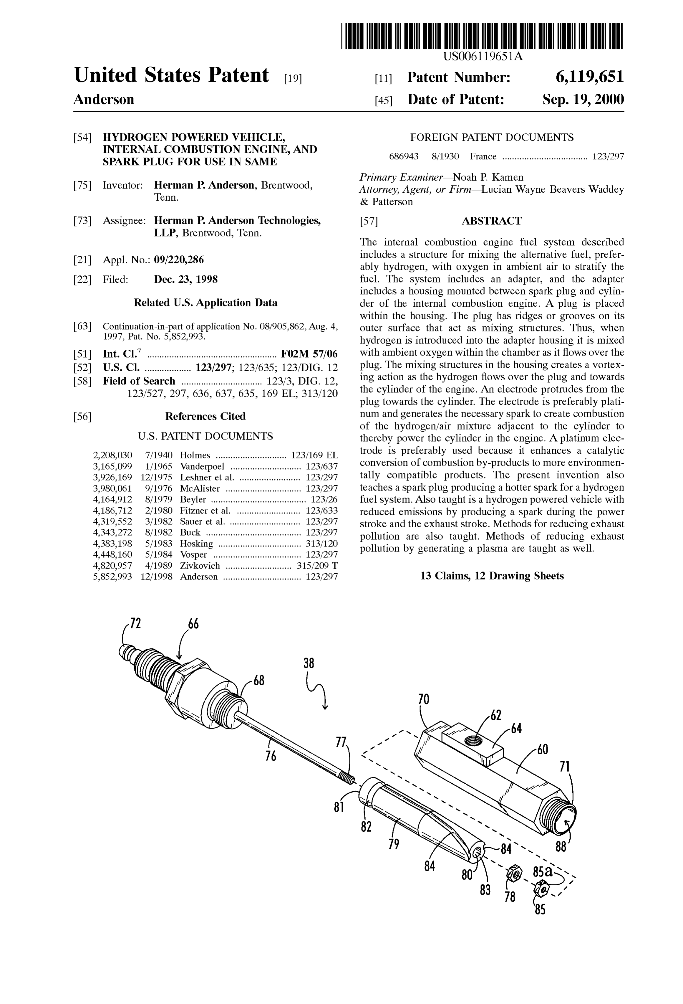
United States Patent (19) 11 Patent Number: 6,119,651 Anderson (45) Date of Patent: Sep.19, 2000 54 HYDROGEN POWERED VEHICLE, FOREIGN PATENT DOCUMENTS NESSINENSINE, AND 686943 8/1930 France ................................... 123/297 Primary Examiner Noah P. Kamen 75 Inventor: Herman P. Anderson, Brentwood, Attorney, Agent, or Firm-Lucian Wayne Beavers Waddey Tenn. & Patterson 73 Assignee: Herman P. Anderson Technologies, 57 ABSTRACT LLP, Brentwood, Tenn.
The internal combustion engine fuel System described includes a structure for mixing the alternative fuel, prefer 21 Appl. No.: 09/220,286 ably hydrogen, with oxygen in ambient air to Stratify the 22 Filed: Dec. 23, 1998 fuel. The System includes an adapter, and the adapter includes a housing mounted between Spark plug and cylin
Related U.S. Application Data der of the internal combustion engine. A plug is placed within the housing. The plug has ridges or grooves on its 63 Continuation-in-part of application No. 08/905,862, Aug. 4. outer Surface that act as mixing structures. Thus, when 1997, Pat. No. 5,852.993. hydrogen is introduced into the adapter housing it is mixed (51) Int. Cl." ..................................................... F02M 57/06 with ambient oxygen within the chamber as it flows over the 52 U.S. Cl. ................... 123,297; 123/635; 123/DIG. 12 plug. The mixing structures in the housing creates a vortex 58 Field of Search ................................. 123/3, DIG. 12, ing action as the hydrogen flows over the plug and towards 123/527, 297, 636, 637, 635, 169 EL; 313/120 the cylinder of the engine. An electrode protrudes from the plug towards the cylinder. The electrode is preferably plati 56) References Cited num and generates the necessary Spark to create combustion of the hydrogen/air mixture adjacent to the cylinder to
2,208,030 7/1940 Holmes ........ 123/169 EL trode is preferably used because it enhances a catalytic 3,165,099 1/1965 Vanderpoel ...... ... 123/637 conversion of combustion by-products to more environmen 3,926,169 12/1975 Leshner et al. .. ... 123/297 tally compatible products. The present invention also 3,980,061 9/1976 McAlister ........ . . 123/297 teaches a Spark plug producing a hotter Spark for a hydrogen 4,164,912 8/1979 Beyler ......................................, 123/26 fuel System. Also taught is a hydrogen powered vehicle with 4,186,712 2/1980 Fitzner et al. .......................... 123/633 reduced emissions by producing a Spark during the power 4,319,552 3/1982 Sauer et al. ............................. 123,297 stroke and the exhaust stroke. Methods for reducing exhaust 4,343,272 8/1982 Buck ............ ... 123/297 pollution are also taught. Methods of reducing exhaust 4,383,198 5/1983 Hosking ... ... 313/120 pollution by generating a plasma are taught as well. 4,448,160 5/1984 Vosper ......... ... 123/297 4,820,957 4/1989 Zivkovich ... 315/209 T 5,852,993 12/1998 Anderson ................................ 123/297 13 Claims, 12 Drawing Sheets
Page 2
r a /
s /2
y1 - -
Y --
w &M W - - -A - / v N.
t a V v. N\, l f A
41 - - - -ae area--- - - - - - -
W f
l ----- - - - - - - - - - - - T - - - - - - - - - - - - - - - - - - - - - - - - - - r r
w w W a W w a' f y w w a w - - -- - w s M A w W. a \ w. . . . . . -- --- - --- -- ---------- --- W Y W a N a 1. Y 1 -1
Page 3
Drawing sheet — no readable text.
Page 4
Drawing sheet — no readable text.
Page 5
Drawing sheet — no readable text.
Page 6
Drawing sheet — no readable text.
Page 7
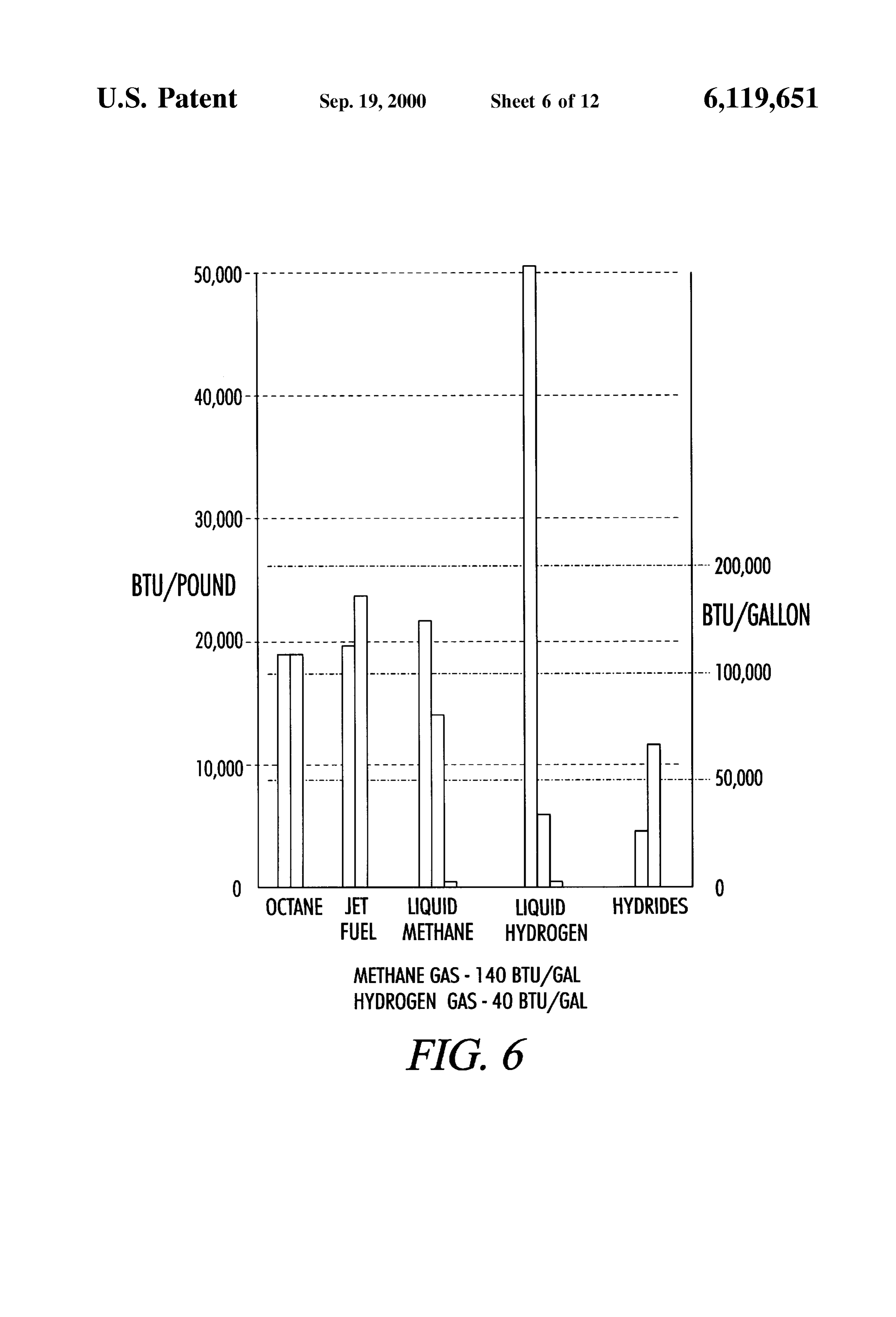
BTU/POUND -- - -- - - - - - - - - -- - - - - - - - - - - - - - - - - - - - - - -- - - - - - - -- -- - - - - - - - - -- - - -- - -- - - -- - -- - - - - - - - - - - 200,000
O OCTANE JET LIQUID
FUEL METHANE HYDROGEN
METHANE GAS-140 BTU/GAL
HYDROGEN GAS-40 BTU/GAL
FIG. 6
Page 8
Drawing sheet — no readable text.
Page 9
Drawing sheet — no readable text.
Page 10
Drawing sheet — no readable text.
Page 11
Drawing sheet — no readable text.
Page 12
Drawing sheet — no readable text.
Page 13
Drawing sheet — no readable text.
Page 14
HYDROGEN POWERED VEHICLE, reference. However, cooling hydrogen makes it more diffi INTERNAL COMBUSTION ENGINE, AND cult to ignite. This is because hydrogen is a dry fuel whereas SPARK PLUG FOR USE IN SAME gas is generally considered a wet fuel. Thus to reduce fuel pollution one prefers to utilize a fuel Such as hydrogen and
This application is a continuation-in-part of U.S. patent ignite it with a hotter Spark.
application Ser. No. 08/905,862 filed Aug. 4, 1997 by One patent discussing very high energy (VHE) ignition Herman P. Anderson, entitled “Fuel System For Internal systems is U.S. Pat. No. 5,207,208 issued to Ward, entitled Combustion System And Adapter For Use In Same”, now “Integrated Convertor High Power CD Ignition”, issued U.S. Pat. No. 5,852,993. U.S. patent application Ser. No. May 4, 1993. U.S. Pat. No. 5,207,208 is hereby incorporated 08/905,862 is hereby incorporated herein by reference. herein by reference. Pat. 208 teaches very high energy
BACKGROUND OF THE INVENTION
ignition systems, for instance on the order of 36K volts. It teaches Voltage doubling utilizing pulsating Sparks of peak
The present invention relates generally to a fuel System current on the order of two amps. While 36K volts may at for internal combustion engines that enables the invention to times be adequate, it is preferable to achieve a higher Voltage utilize alternative fuels, and, more particularly to an 15 in the ignition chamber when using hydrogen. improved fuel System for an internal combustion engine and It is known in the art to use a direct ignition System, also an adapter and Spark plug for use in Same. referred to as a distributorless ignition System, to increase The problems of air pollution caused by automobiles, the Spark plug Voltage. Such direct ignition Systems use a lawnmowers and other vehicles that have internal combus “waste spark' method of spark distribution. Each cylinder is tion engines powered by gasoline is well documented. This paired with its opposing cylinder in the firing order (1-4, 2-3, problem is particularly described in an article in the San on a four cylinder, 1-4, 2-5, 3-6 on a V6) so that one cylinder Diego Union Tribune, Wednesday, Sep. 25, 1996 and in on compression fires simultaneously with its opposing cyl Popular Science, August 1996. Indeed, under the Clean Air inder on exhaust Stroke. Since the cylinder on exhaust Stroke Act, in the next few years cars that do not run on Standard 25 requires very little of the available Voltage to fire its plug, fossil fuels like gasoline will be required in Several States. most of the Voltage is used to fire the cylinder on the Currently, there are no vehicles available to meet this need. compression Stroke.
Thus, it will be appreciated by those skilled in the art that U.S. Pat. No. 4,462,380 discusses a distributorless igni there has been a push to Seek other fuels for use in internal tion system. U.S. Pat. No. 4,462,380 entitled “Enhanced combustion engines. These fuels include methane, propane Spark Energy Distributorless Ignition System” issued Jul. and gasohol. 31, 1984 by Asik is hereby incorporated herein by reference. Hydrogen has also been characterized as a promising fuel Pat. 380 teaches a distributorless ignition system of an Source. See Department of Energy publication entitled internal combustion engine which has a Supplementary “Hydrogen Fuel”, printed in 1978, U.S. Government Print Spark energy module to increase Spark energy. Each high ing Office, U.S. Department of Energy, Office of Public 35 Voltage terminal is connected to a Single Spark plug and each Affairs, Washington, DC 20585. Particularly, the graph ignition coil primary is alternately energized and quickly presented in FIG. 6, which is copied from this publication, de-energized, producing opposite polarity ignition Voltages shows the potential for hydrogen in BTUS/Lb. However, the at each coil terminal. As a result, pairs of Spark plugs are mass energy density for hydrogen is low; and thus, hydrogen alternately fired, with each firing pair occurring in a com needs to be compressed before its energy potential can be 40 pression or exhaust Stroke and thereby providing the proper realized. Hydrogen is a “dry fuel” that is more difficult to ignition to the engine. Asik asserts that firing a Spark plug ignite than “wet fuels.” It becomes more difficult to ignite does not affect engine performance or emissions. AS taught when it is cooled. However, cooling is preferred in most by the instant invention this is incorrect for hydrogen fuels Systems to avoid premature ignition of the fuel. Other when the exhaust is Sparked at a Sufficient Voltage. Systems deliver the hydrogen under pressure to prevent 45 U.S. Pat. No. 5,146,882 (Brinkman) teaches use of spe ignition in the Supply line, which is a form of pre-ignition. cific wet fuel mixtures in conjunction with direct ignition No prior art fuel System has been able to capture the energy systems (D.I.S.). It teaches that technical breakdown volt of hydrogen. ages for typical Spark plugs are on the order of 15–20 kV and Several fuel systems for use with hydrogen have been DIS typically yield between 30 kV-40 kV. U.S. Pat. No. proposed. Examples are described in U.S. Pat. Nos. 4,167, 50 5,146,882, entitled “Method And Apparatus For Cold Start 919; 4,253,428; 4,016,836; 4,178,882; 5,222,993; 5,085, ing A Spark Ignited Internal Combustion Engine Fueled 176; and 5,085,176. The problem with these prior art fuel With An Alcohol-Based Fuel Mixture”, by Brinkman, et al., Systems is they cannot take advantage of the alternative fuels issued Sep. 15, 1992, is hereby incorporated herein by to generate Sufficient power from the fuels to drive an reference. The previously referenced prior art discusses internal combustion engine for use in a lawn mower, auto 55 alternate fuels and fuel Systems but does not teach a method mobile or other vehicle. AS noted above, this is a particular of achieving a Sufficient Voltage with a hydrogen System. problem when hydrogen is used as a fuel. Additionally, the What is needed, then, is a fuel system for an internal prior art Systems do not address the problem of back fire, i.e. combustion engine that provides a way to generate Sufficient undesired explosion of the fuel in the cylinder during the power from the alternative fuels and that reduces backfire exhaust Stroke of the internal combustion engine. 60 problems. Such a System is lacking in the prior art. Also Premature ignition or backfire is often a problem with lacking in prior art is a System utilizing alternate fuels with hydrogen fueled systems. U.S. Pat. No. 4,383,198 (Hosking) reduced pollution capabilities. Also lacking is a way of teaches a fuel injection Spark plug with a pre-cooling generating Sufficient Voltage Spark to ignite the alternate chamber to avoid premature ignition indentination of a fuel.
gaseous fuel Supplied to the Spark plug. U.S. Pat. No. 65 The following U.S. Patents discuss Spark plugs designed 4,383,198, Hosking, entitled “Fuel Injection Spark Plug', for gas internal combustion engines to reduce radio fre issued May 10, 1983, is hereby incorporated herein by quency noise and interference. U.S. Pat. No. 4,224,554,
Page 15
entitled “Spark Plug Having A Low Noise Lever issued to and cylinder of the internal combustion engine. A plug is Nishio et al., Sep. 23, 1980 is hereby incorporated herein by placed within the housing. The plug has ridges or grooves on reference. U.S. Pat. No. 4,029,990 entitled “Spark Plug its outer Surface that act as mixing Structures. Thus, when Construction' issued to Nagy et al., Jun. 14, 1977 is hereby hydrogen is introduced into the adapter housing it is mixed incorporated herein by reference. with ambient oxygen within the chamber as it flows over the
SUMMARY OF THE INVENTION
plug. The mixing Structures on the plug create a Vortexing action as the hydrogen flows over the plug and towards the
It is an object of this invention to provide an improved cylinder of the engine.
fuel system for use with alternative fuels. An electrode protrudes from the plug towards the cylin It is a further object of this invention to provide an der. The electrode is preferably platinum and generates the improved fuel System for use particularly with hydrogen, necessary Spark to create combustion of the hydrogen/air and particularly to enhance the mass energy density of mixture adjacent to the cylinder to thereby power the hydrogen. cylinder in the engine. A platinum electrode is preferably It is an object to provide a hotter Sparking plug to ignite used because it enhances a catalytic conversion of combus the fuel. 15 tion by-products to more environmentally compatible prod
It is still a further object of this invention to provide an uctS.
adapter for use in a fuel System for an internal combustion Thus, the combination of the compression action gener engine that enhances the power obtained from the alternative ated by the conventional piston and push rod within the fuels. cylinder of the engine in conjunction with the hydrogen/air It is still a further object of this invention to provide an mixing Structure that Vortexes the hydrogen/air create com improved fuel System for an internal combustion engine that pressed hydrogen that is mixed with a combustion does not present the environmental hazards of a Standard facilitator, i.e. oxygen in the ambient air to enable the System gasoline engine by providing reduced or Zero emission of of this invention to capture the abundant energy found in environmentally harmful gases. hydrogen fuel.
It is yet a further object of this invention to provide an The enhanced mixing capabilities of this invention is also improved fuel System for an internal combustion engine that adaptable for use with other alternative fuels. Such as natural can use an alternative fuel and can use gasoline to facilitate gas, alcohol, propane and the like.
the transition from gasoline to alternative fuels. One embodiment of the present invention is for a hydro It is yet a further object of this invention to provide an gen powered vehicle including an internal combustion improved fuel System for an internal combustion engine that engine operably connected to power the vehicle and adapted reduces backfire problems. to connect to a hydrogen Supply line. The internal combus tion engine comprises a cylinder operably connected to the
It is yet a further object of this invention to provide an Supply improved fuel System for an internal combustion engine that a Sparkline; plug a piston operably disposed in the cylinder; and having an electrode assembly in operable reduces backfire problems by cooling the electrode in the 35 Sparking communication with the cylinder, wherein the Spark plug with the hydrogen gas fuel. Spark plug is capable of producing a Spark of at least 45 kV. It is an object to reduce backfire by providing hydrogen at Preferably the Spark plug comprises a housing having a a Sufficient pressure to reduce backfire and igniting it with a Sparking end and a hollow chamber containing the electrode hotter spark (i.e. a higher voltage). assembly. The electrode assembly comprises an electrode It is still a further object of this invention to provide an 40 having a connector end and a Sparking end, wherein the adapter for use in a fuel System for an internal combustion Sparking end is positioned adjacent to the housing Sparking engine that enhances the power obtained from the alternative end. The electrode assembly preferably comprises a coil fuels. electrically connected to the electrode connector. It is a further object to generate a plasma field in a cylinder 45 Preferably the housing comprises a fuel inlet port in fluid to burn residual exhaust and reduce emissions. communication with the Supply line, and an insulator Sur It is yet a further object of this invention to provide a rounding the electrode assembly, wherein the insulator is direct injection fuel System wherein fuel is injected directly positioned in the hollow chamber. Preferably the insulator into the cylinder. comprises an Outer Surface defining a first fuel channel It is an object to provide a "2-fire' direct injection System, 50 having a first respective fuel exit port, wherein the first fuel wherein the fuel is ignited during the power Stroke and the channel is in fluid communication with the fuel inlet port and exhaust Stroke. the fuel exit port exits into the cylinder. It is yet a further object of this invention to provide a way The present invention also includes a method of operating to convert the Standard induction fuel System of a lawn an internal combustion engine comprising Supplying hydro mower to a direct injection fuel System wherein fuel is 55 gen fuel to the engine and creating a Spark in the cylinder injected directly into the cylinder. during the power Stroke and the exhaust Stroke, wherein the It is yet a further object of this invention to provide a way Spark created during the power Stroke is at least 45 kV. In to convert the indirect injection fuel System of an automobile one embodiment the spark is at least 70 kV. In certain to a direct injection fuel System wherein fuel is injected embodiments the method comprises generating plasma dur directly into the cylinder. 60 ing the exhaust Stroke. The exhaust fuel converts to an The internal combustion engine fuel System of this inven exhaust emission and coalesces with the plasma, thereby tion includes a structure for mixing the alternative fuel, reducing fuel pollution.
preferably hydrogen, with oxygen in ambient air to Stratify Accordingly, it is an object in the invention to provide a the fuel. The term “alternative fuels' is known in the art and Spark plug producing a Sufficiently hot Spark to ignite is meant to refer to fuels other than conventional gasoline. 65 hydrogen fuel, including cooled hydrogen fuel. The invention in one embodiment comprises an adapter, Another object of the present invention is to provide a the adapter including a housing mounted between Spark plug device for reducing fuel exhaust emissions.
Page 16
S 6
Another object of the present invention is to provide a FIG. 21 is a cross section view of the insulator shown in cleaner burning engine. FIG. 19 along section line 21-21. Another object is to provide a Spark plug for reducing FIG. 22 is a cross section view of the insulator shown in emissions. FIG. 19 viewed in the direction of view line 22-22. Another object of the present invention is to provide a FIG.23 is an elevated section view of the insulator shown device functional with dry fuels. Use of the term hydrogen, in FIG. 19.
as discussed herein, is intended to encompass Such dry fuels. DESCRIPTION OF THE PREFERRED However the term as used excludes Such wet fuels as gas and EMBODIMENT alcohol.
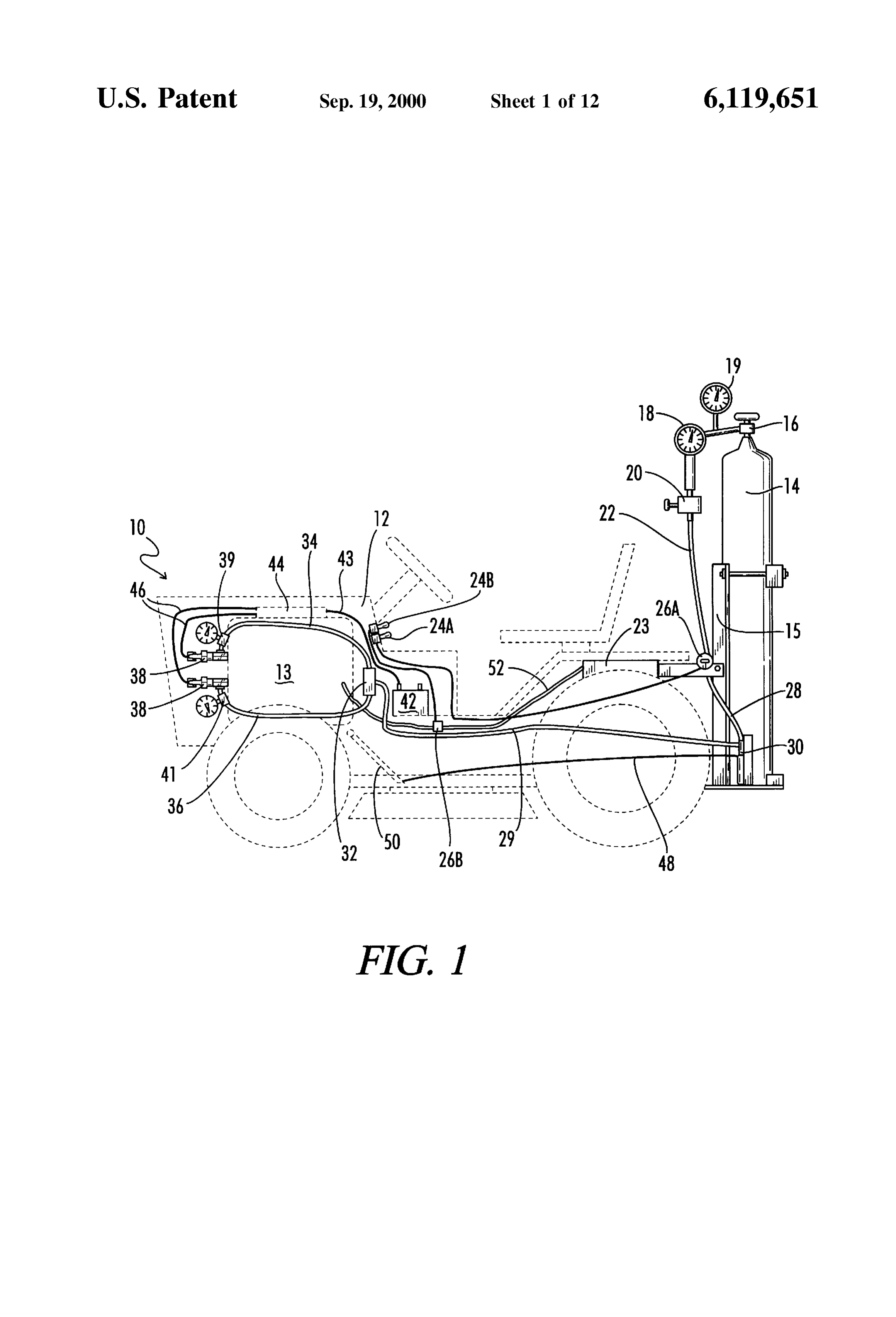
Another object of the present invention is to provide an Referring now to the drawings, wherein like reference integrated fuel System adapted to provide these and objec numerals refer to like parts throughout, the fuel System is tives. referred to generally at 10. The fuel system of this invention Other objects and advantages of the present invention will isSystem, contemplated for use with an internal combustion power
Such as an internal combustion engine or Such as a be apparent to those of skill in the art by reference to the 15 home heating System. Fuel System 10 is portrayed in this teachings disclosed herein, including the attached drawings, case as connected to a Standard lawn mower. The lawn detailed description of exemplary embodiments, and claims. mower is shown in phantom at 12 in FIG. 1. The lawn BRIEF DESCRIPTION OF THE DRAWINGS mower is a conventional lawn mower as can be purchased from a company such as Murray of Ohio. The internal
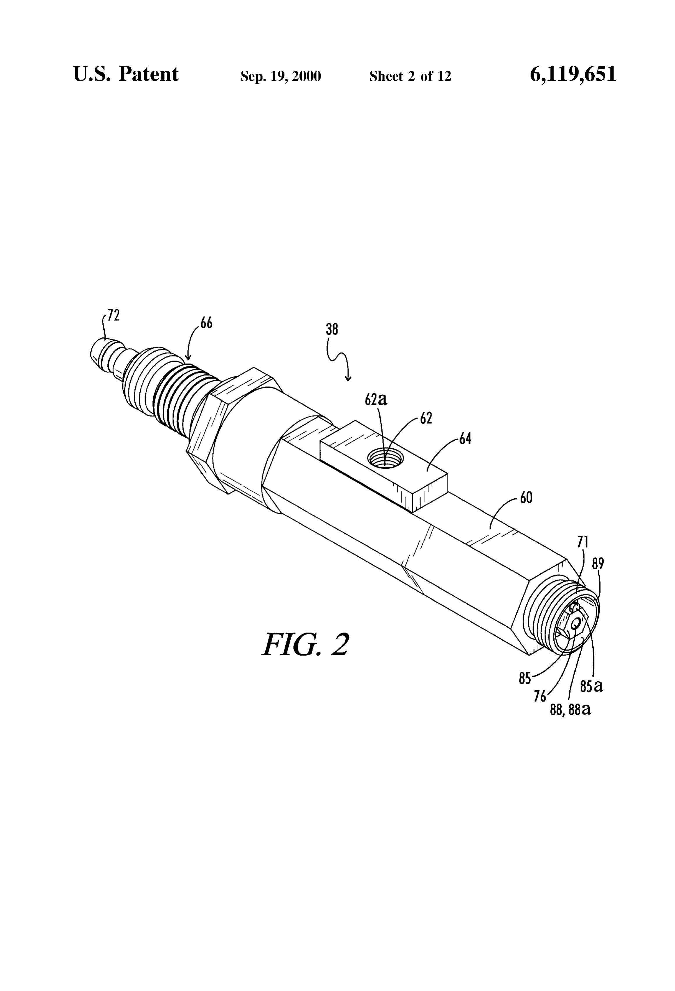
FIG. 1 is a plan view of the fuel system of this invention combustion engine in the lawnmower is a Standard 4-cycle with a lawn mower shown in phantom. engine with two cylinders and developS 18 horsepower. A FIG. 2 is a perspective view of the adapter of the fuel Suitable example can be purchased from Briggs & Stratton, System of this invention. Milwaukee, Wis. 53201.
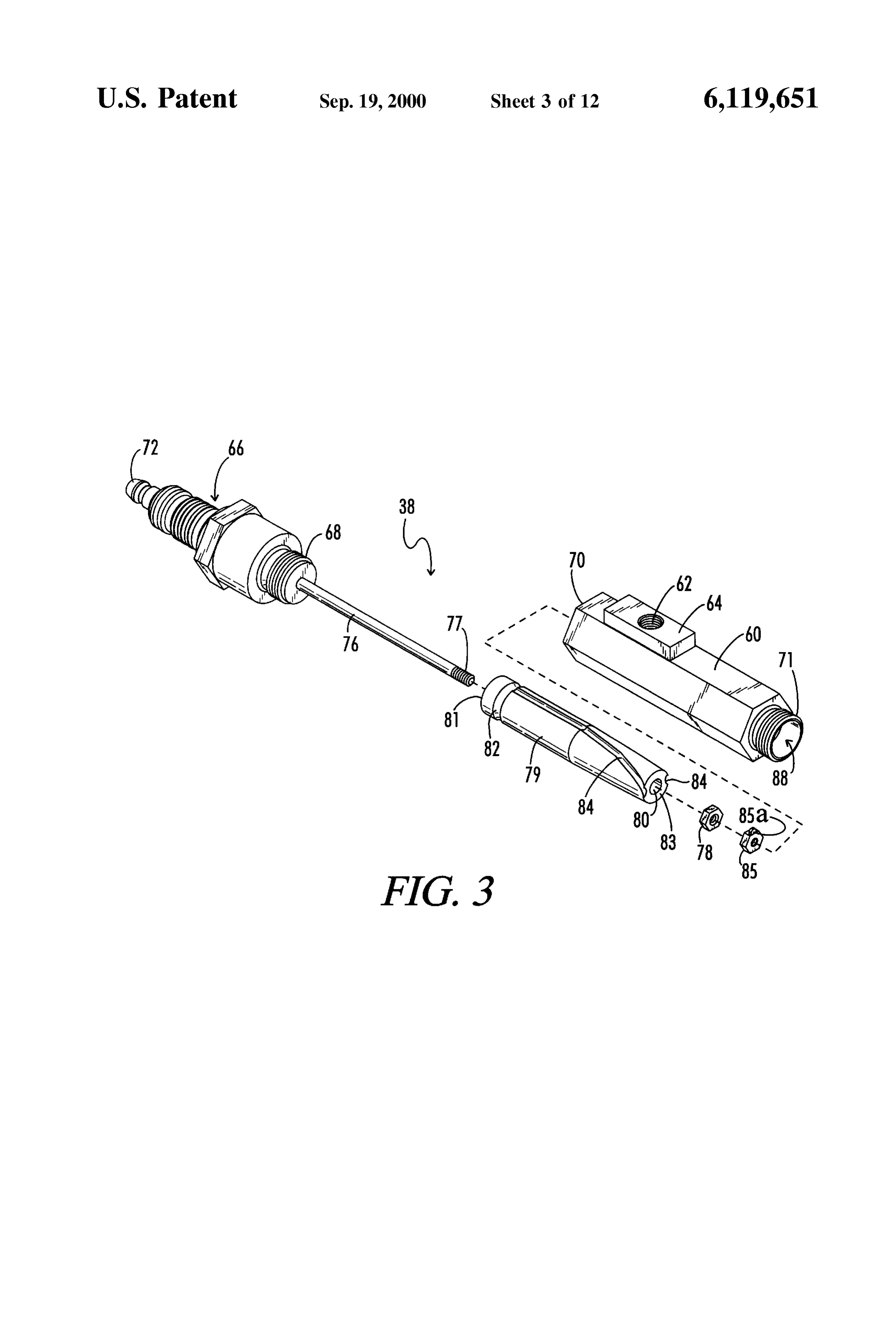
FIG. 3 is an exploded perspective view of the adapter of 25 Referring particularly to FIG. 1, system 10 includes fuel the fuel system of this invention. tank 14 that is mounted to lawn mower 12 via mounting assembly 15. In the preferred embodiment, fuel tank 14
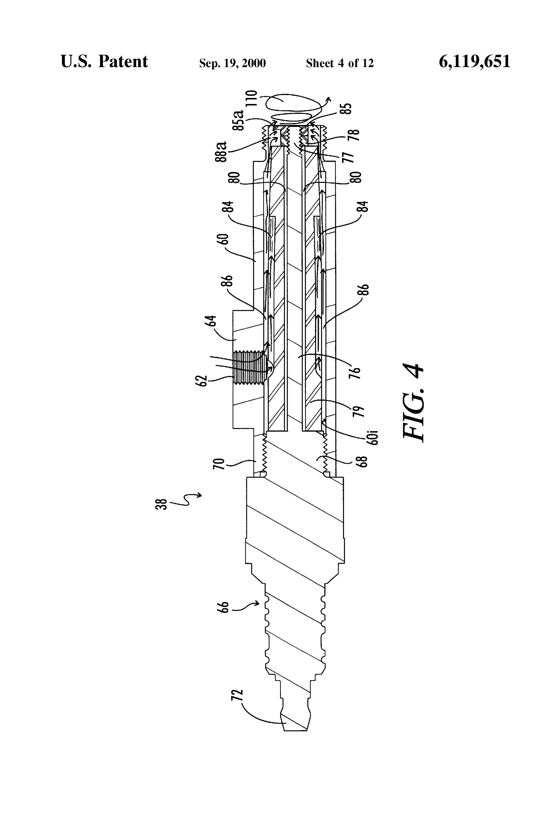
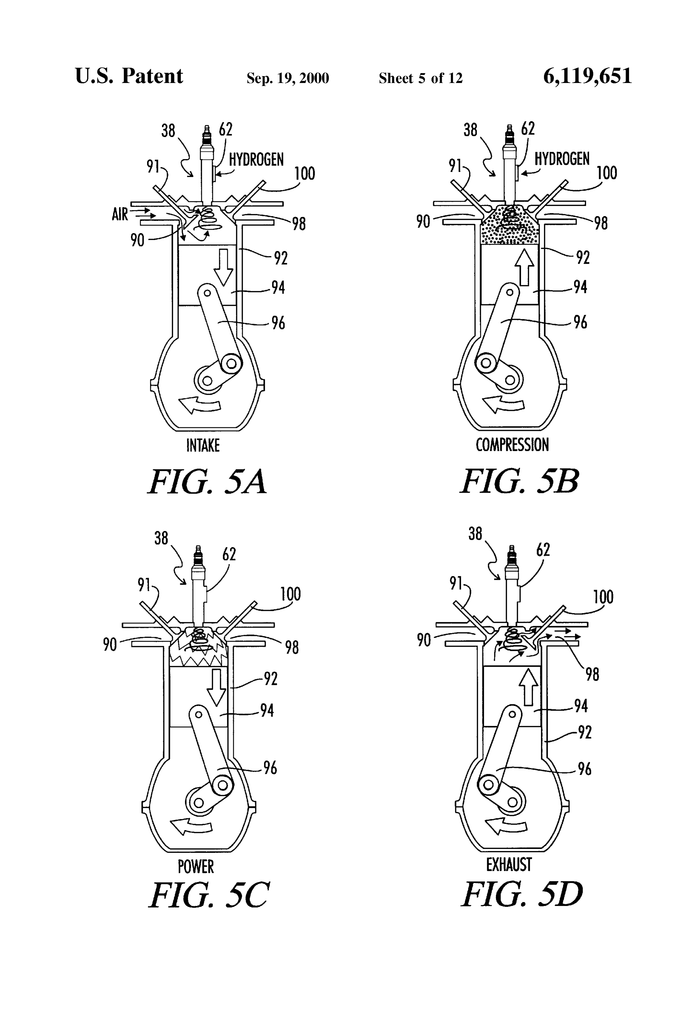
FIG. 4 is a cross-sectional view of the adapter of the fuel includes hydrogen gas. Accordingly, for the purposes of the System of this invention. foregoing detailed description, hydrogen gas will be FIGS. 5A-5D are a schematic of the 4 cycle combustion described.
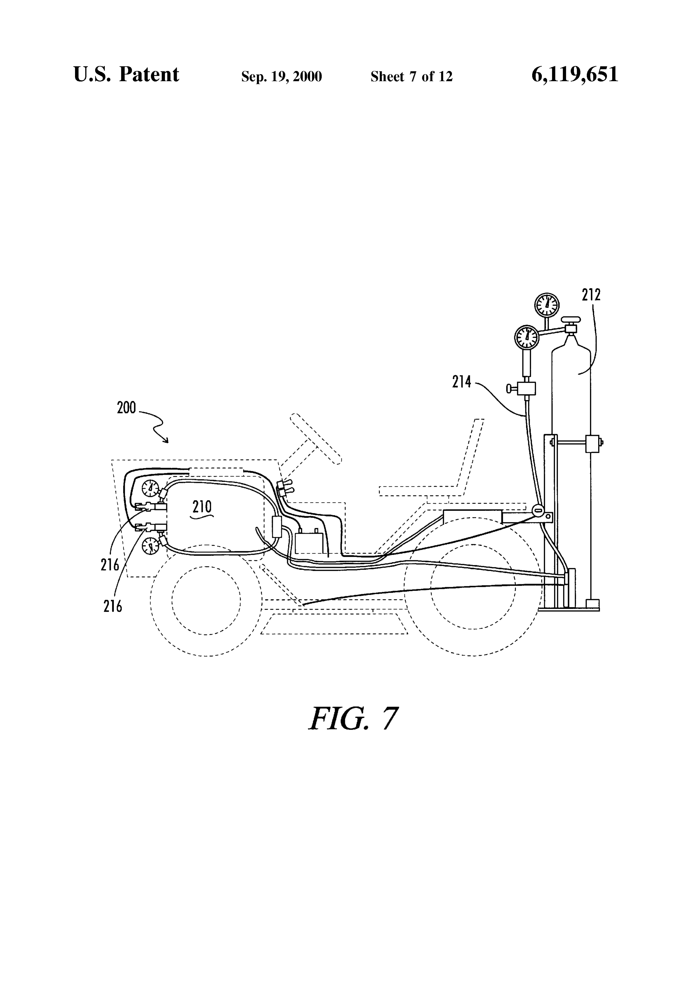
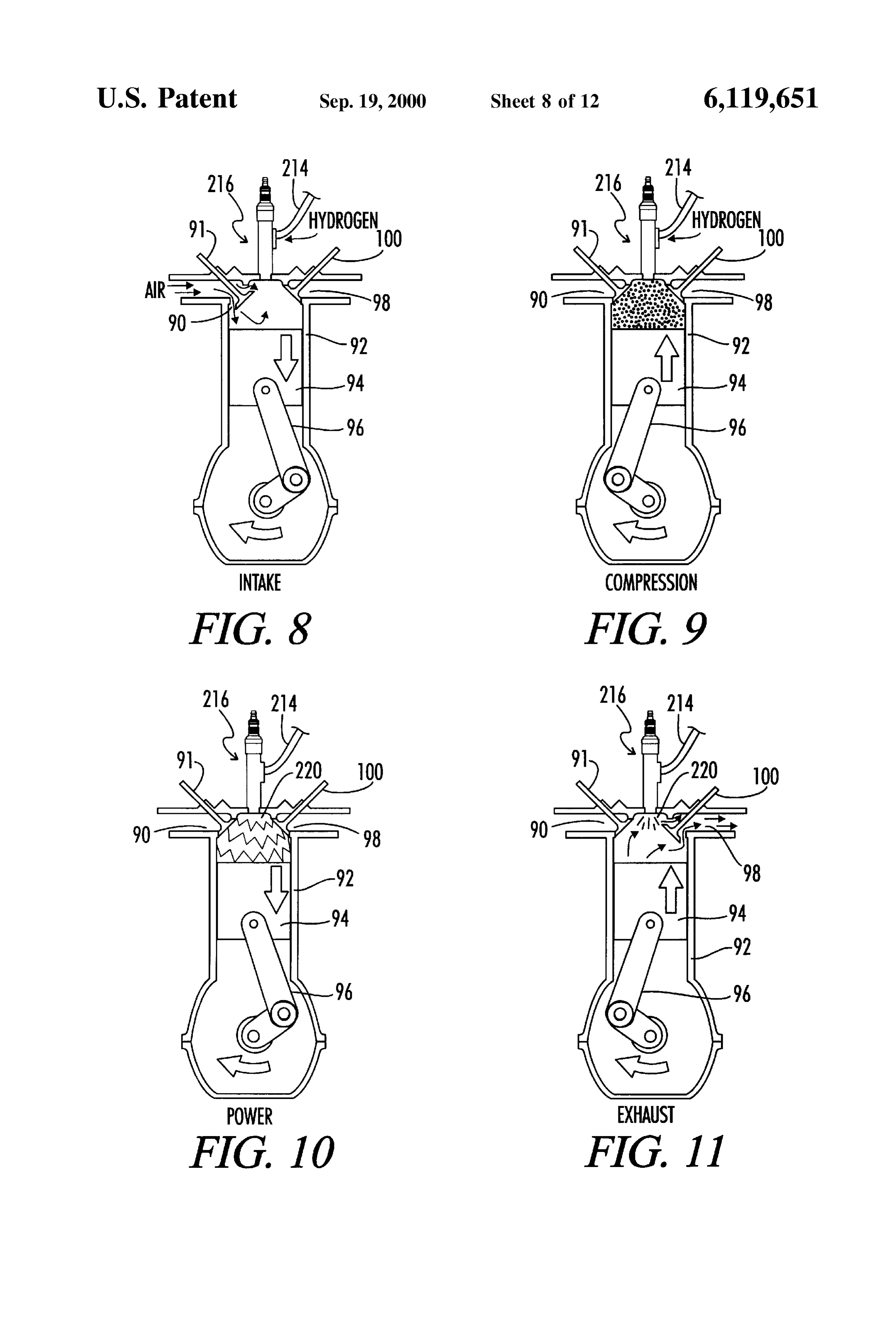
in an internal combustion engine including the adapter of A line 22 begins at fuel tank 14 and proceeds to back-flow this invention. valve 16. Back-flow valve 16 is a standard valve and is FIG. 6 is a graph which shows the energy potential for available from AirCo Gases Company, 575 Mountain hydrogen in BTUs/Lb. Avenue, Murray Hill, N.J. 07974, part no. WCS CV-4M. PSI FIG. 7 shows a vehicle of the present invention utilizing 35 tank gauge 19 is inserted in line 22 between back-flow valve hydrogen fuel. 16 and flow pressure gauge 18. PSI tank gauge 19 is FIG. 8 depicts an intake stroke of a cylinder connected to available from AirCo Gases Company also, part no. WCS a hydrogen Source. CV5M, and serves as an indicator of fuel remaining in the FIG. 9 depicts a compression stroke of a cylinder con tank 14. Flow pressure gauge 18 is used to monitor the flow nected to a hydrogen Source. 40 of the hydrogen in pressure units. The flow is started using valve
FIG. 10 depicts a power stroke of a cylinder connected to preSSure 16. The optimal flow pressure is 25 pounds of flow a hydrogen source. The spark plug shown in FIG. 10 is from the tank 14 to the cylinder of the engine. depicted Sparking. The flow of hydrogen is regulated via valve 20 that is part of gauge 18. Thus, when Valve 20 is opened, hydrogen
FIG. 11 depicts a cylinder in an exhaust Stroke connected 45 proceeds through line Section 22 to hydrogen flow Solenoid to a hydrogen Source, wherein the Spark plug is sparking 26A. The user can access the hydrogen fuel by flipping during the exhaust Stroke. hydrogen flow switch 24A into the “on” mode so that FIG. 12 shows an elevated side view of a spark plug of the hydrogen gas in line 22 can proceed through hydrogen flow present invention. Solenoid 26A and into line section 28. FIG. 13 shows a plan view in the direction of view line 50 Throttle 30 regulates the flow of hydrogen from line 13-13 of the spark plug shown in FIG. 12. section 28 into line section 29 and ultimately, to engine 13. FIG. 14 depicts a plan view in the direction of view line Throttle 30 is connected to throttle pedal 50 via includes 14-14 of the spark plug shown in FIG. 12. throttle cable 48. Throttle pedal 50 also operates the butterfly FIG. 15 depicts an elevated side section view of the spark ValvesC.in the carburetor in engine 13 in a conventional plug shown in FIG. 12. 55
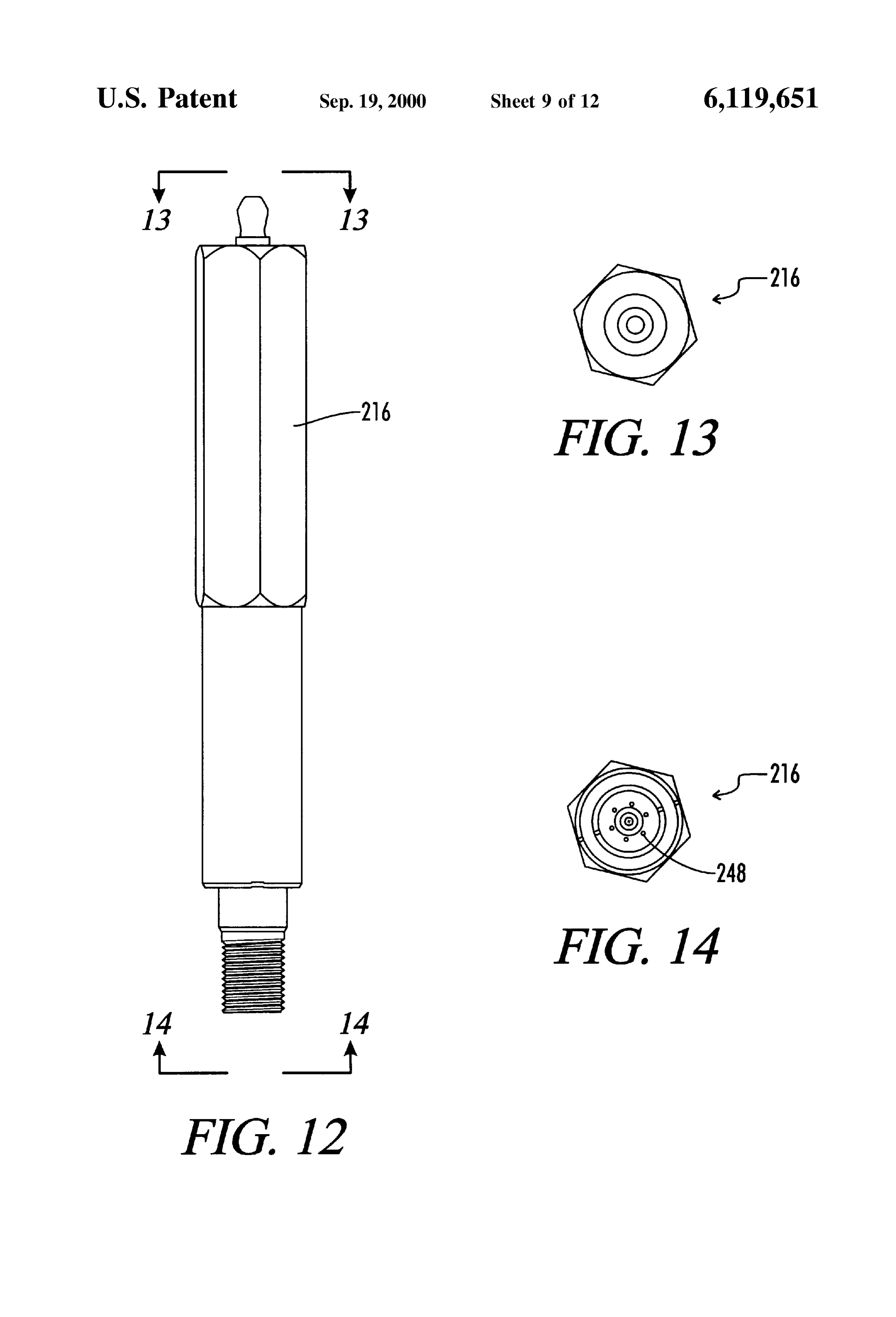
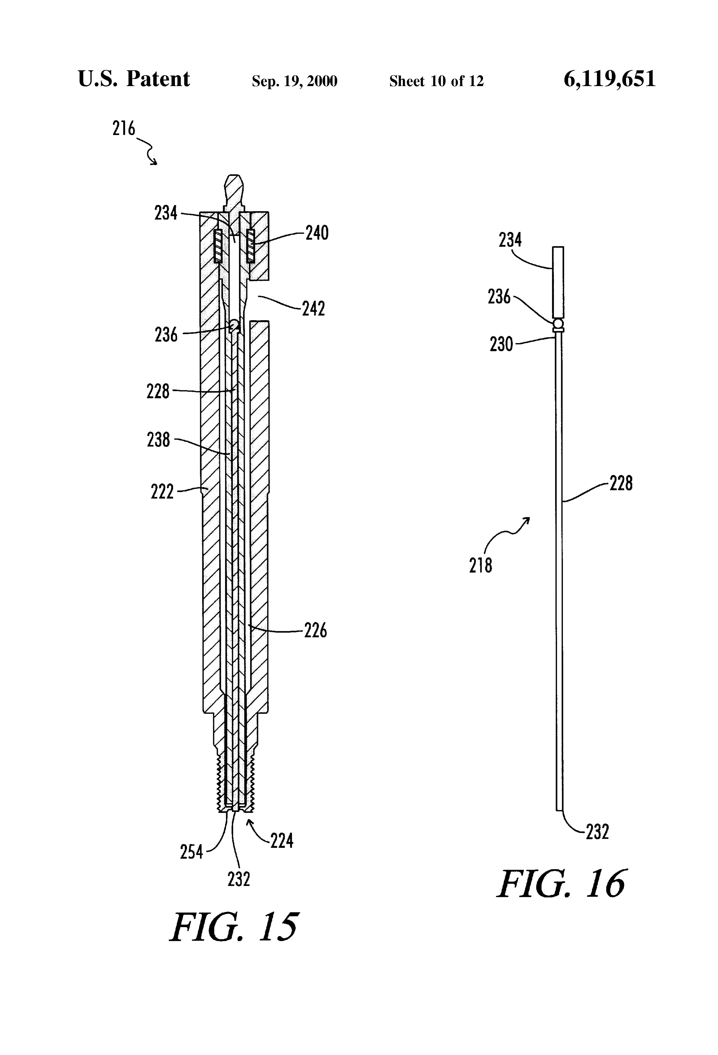
FIG. 16 shows a electrode assembly which is disposed in byASa an option, the throttle can be controlled electronically digital fuel controller product. Such a product is the hollow chamber depicted in FIG. 15. commercially available from Autotronic Controls Corp., FIG. 17 shows a section view of the spark plug housing 1490 Henry Brennan Drive, El Paso, Tex. 79936. clearly showing the hollow chamber and a torridal ground 60 Line portion 29 proceeds through splitter 32 and is split electrode.
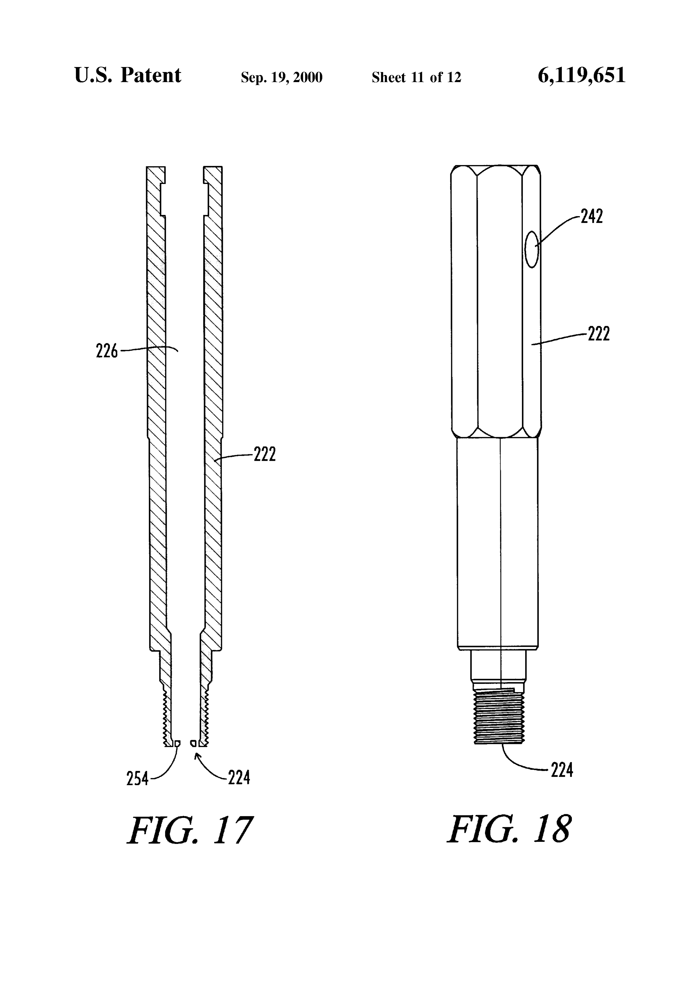
into upper line 34 and lower line 36. Lines 34 and 36
FIG. 18 depicts an elevated side view of the spark plug proceed to adapters 38. Additional back-flow prevention housing and a fuel inlet port. valves 39 and 41 are mounted between lines 34 and 36 and FIG. 19 depicts an insulator comprising fuel channels and adapters 38. Braided Teflon(R) is the preferred material for fuel exit ports. 65 the fuel lines of the system.
FIG. 20 is a top plan view of the insulator shown in FIG. Battery 42 is connected via battery cable 43 to magneto 19 viewed in the direction of view line 20–20. 44. Magneto 44 then controls the current through spark plug
Page 17
lines 46 to adapters 38 in a conventional manner. Thus, the Spark gap distance is 25/1000 of an inch. Of course, the regulation of the Spark that ignites the fuel in the cylinder of electrode may be coterminus with the plug distal end 83. engine 13 is conventional. Additionally, the intake of air into AS best Seen in FIG. 4, where arrows represent gas flow, the engine 13 is accomplished through the Standard carbu hydrogen gas flows into chamber 60 via port 62. The retor System of engine 13. In a car, the Sparking of the Spark hydrogen gas cools electrode 76, which facilitates combus plugs can be controlled by the standard distributor/battery tion. Stratifying grooves 84, preferably there are two, act to ignition System. mix the hydrogen that is flowing into housing 60 with A second solenoid 26B controls the flow of gasoline from ambient air therein. Though more or leSS Vortex creating tank 23 through gasoline line 52. Solenoid 26B is controlled grooves (stratifying grooves) may be desired. Typically this by Switch 24B. Throttle 30 is connected to gasoline line 52 will depend on the relative dimensions of the grooves and and can also be used to control the flow of gasoline to engine diameter of the plug as well as the preSSure or Velocity of the 13. Thus, this invention can be used with both an alternative mixture in the housing. The mixing occurs within Void space fuel and gasoline. 86 of housing 60 and creates a Vortexing or tornado action. Referring now to FIGS. 2, 3 and 4, the adapter 38 of this 15 Plug 79 tapers as it proceeds from its distal end 81 to its invention is shown in more detail. Adapter 38 includes proximal end 83. Thus, proximal end 83 is smaller in housing 60. A threaded port 62 is formed into housing 60 diameter than distal end 81. This provides additional space through port block 64. Hydrogen lines are threadably con within void space 86 for the mixing of the hydrogen and air. nected to the adapter 38 via port 62. Port 62 is also referred The Stratified hydrogen/air are twisting in a vortex fashion to as an entrance port. The entrance port has an entrance area when leaving housing 60 via exit port 88. The vortexing 62a. action produced by grooves 84 on the plug 79 creates a Adapter 38 also includes spark plug 66 which is effec “tornado' 110 of hydrogen/air with a hollow center that tively a Standard Spark plug except for the modification to generates a vacuum. Similar effect would result were the the electrode as described below. Spark plug 66 includes a grooves to be placed on the housing. The vacuum propels the threaded end 68 which is threadably received in the threaded 25 hydrogen/air mixture into the cylinder of the engine for upper end 70 of housing 60. Spark plug wires 46 (as seen in combustion. Such mixing cannot be accomplished in a FIG. 1) are connected to connector end 72 of spark plug base conventional induction System.
66. Referring now to FIG. 5, a schematic of the system of this Electrode 76 protrudes from spark plug 66 and is of a invention is portrayed, with arrows representing gas flow. length sufficient so that the threaded tip 77 (best seen in Hydrogen flows in through port 62 through adapter 38 and FIGS. 3 and 4) of the electrode 76 is proximate to the into cylinder 92. Air enters cylinder 92 through air intake 90 cylinder of the internal combustion engine when the adapter and air intake valve 91. The stratified hydrogen/air mixture 38 is mounted. In one embodiment the electrode 76 is is compressed in the compression Stroke of the engine via coterminus with an exit port 88 of the adapter 38. This most piston 94 and push rod 96, which are standard structures in clearly is shown in FIG. 4. Electrode 76 is preferably 35 an internal combustion engine. In the power Stroke shown in platinum to enhance catalysis of combustion by-products, as FIG. 5-C, a Spark is generated in the compressed Stratified will be more fully discussed below. hydrogen/air mixture ignites and drives piston 94 and push Adapter 38 also includes plug 79. Plug 79 includes an rod 96 to power the engine.
axial internal void space 80. Thus, plug 79 fits over electrode The mass energy density of hydrogen is enhanced through 76 via internal void space 80. Plug 79 preferably comprises 40 the increased pressure on the hydrogen exerted by piston 94 a ceramic material that acts as a good insulator. A Suitable on the hydrogen/air mixture within the cylinder 92 in the Source for ceramic plug 79 is AM/PRO Machinery, Inc. 134 uptake Stroke in an internal combustion engine. The pres Church Street, Plain City, Ohio 43064-1321. Surized and well-mixed hydrogen/air mixture is rapidly An important aspect of this invention is found on the ignited through the Spark because hydrogen has a fast flame external surface of plug 79. An annular groove 82 is formed 45 front. This reduces problems with timing. Thus, the energy on the surface of plug 79 near its distal end 81 so as to be Store found in hydrogen is captured through this System via proximal to the port 62 where hydrogen enters housing 60. the compression of the hydrogen gas within cylinder 92 and Two Stratifying grooves 84 proceed along the Surface of plug via the thorough mixing of hydrogen and air provided by 79 until they reach its distal end 83. It is these mixing adapter 38.
Structures, i.e. annual groove 82 and Stratifying grooves 84, 50 In addition, in the exhaust phase in a four cycle engine a that facilitate the improved power generation from alterna Second Spark is generated from the plug to ensure complete tive fuels as provided by this invention. It will be apparent combustion of by-products. This is enhanced by using an to those skilled in the analogous arts that mixing structure electrode made of platinum. Exhaust leaves cylinder 92 may be formed in the inner Surface of the adapter housing through exhaust port 98. Exhaust port 98 is closed during 60. 55 other phases by exhaust outlet valve 100. Alternatively a combination of Vortex producing Struc In the exhaust stroke, because air valve 91 is closed, the tures is integral with both the plug 79 and adapter housing Substantial component of the gases in cylinder 92 is hydro 60. Also any conventional VorteX producing means should gen. This is also accomplished due to the fact that in the be Sufficient groves, per Se, are not required. System of this invention, the hydrogen is continuously On threaded tip 77 of electrode 76, there are mounted a 60 flowing. When this spark interacts with what is predomi spacer nut 78 and a spark gap nut 85. As best seen in FIG. nately hydrogen, a plasma is formed. This plasma blockS 2, the spark gap nut 85 includes a protrusion 85a that back-flow of air from exhaust port 98. Prevention of back provides the Spark gap between electrode 76 and periphery flow of air prevents the hydrogen fuel system from 89 of the exit port 88 of housing 60. The exit port 88 includes backfiring, which is another common problem of hydrogen an exit area 88a. Preferably, the exit area 88a is no larger 65 fuel Systems. In effect, then, the plasma formed by the than the entrance area 62a, though this is not critical. hydrogen acts as a virtual valve in that the plasma blocks the Preferably, the spark gap nut 85 is brass and the preferred back-flow of air.
Page 18
When the plasma of the hydrogen is generated as positioned in the hollow chamber 226. A ceramic pore 240 described above, UV radiation is generated which also is shown stabilizing the insulator 238 in the hollow chamber facilitates consumption of combustion by-products. This 226. Other methods of locating the insulator in the hollow increases the environmental friendliness of the System. chamber will be apparent to those of skill in the art. In addition to hydrogen the following fuels can be used in An elevated Section view of the housing 222 is shown in this System: natural gas, alcohol, gasohol; propane and FIG.
buthane. A mixture of hydrogen and natural gas can also be in FIG.17.18. An elevated side view of the housing 222 is shown In the exemplary embodiment of the housing 222 used. AS noted above, gasoline can be used in this System shown in FIG. 18, the housing 222 comprises a fuel inlet when Solenoid 26 is used to stop the flow of hydrogen.
Further, it is contemplated that an adapter that is described (not shown). FIG.communication port 242 in fluid 19 depicts an with the Supply line 214 exemplary embodiment of herein for use with an internal combustion engine can also the insulator 238. The insulator 238, shown in FIG. 19, be used with a home heating System Such as a home heating comprises an outer Surface 244 defining a first fuel channel System that may currently use natural gas. The Vortexing action created by the plug would enable appropriate power 246 having a first respective fuel exit port 248. The first fuel to be captured from the hydrogen fuel So as to effectively 15 channel 246 is in fluid communication with the fuel inlet heat a home. port 242. The fuel exit port 248 exits into the cylinder 292. Another embodiment of the invention is a hydrogen FIG. 20 shows a plan view of the insulator 228 shown in powered vehicle 200 shown in FIG. 7. The hydrogen pow FIG. 19 along line 20-20. FIG. 21 shows a section view of ered vehicle 200 includes an internal combustion engine 210 the insulator 228 shown in FIG. 19 viewed along section line operably connected to power the vehicle 200 and adapted to 21-21. FIG.22 depicts a bottom plan view of the insulator connect to a hydrogen Supply 212 through a Supply line 214. 228 shown in FIG. 19 along line 22-22. FIG. 23 shows a Referring to FIG. 8, the internal combustion engine 210 section view of the insulator 228 cut through section line comprises a cylinder 92 operably connected to the Supply 23-23 shown in FIG. 19.
line 214. A piston 94 is operably disposed in the cylinder 92. In the embodiment of the insulator 228 shown in FIGS. A Spark plug 216 having an electrode assembly 218 (not 25 19-22, the insulator outer surface 244 defines a plurality of shown in FIG. 8) is in operable Sparking communication fuel channels 250, including the first fuel channel 246. The with the cylinder 92, wherein the spark plug 216 is capable fuel channels 250 include a plurality of respective fuel exit of producing a spark 220 (shown in FIG. 10) of at least 45 ports 252, including the first fuel exit port 248. This is shown kilovolts. FIGS. 8-11 are substantially similar to FIGS. clearly in FIG. 22. Preferably, the plurality of fuel channel 5A-5D depicting Schematic representations of a 4-cycle exit ports 252 are Spaced equally, or equi-distant, about the piston-cylinder engine. Other piston and cylinder embodi electrode 228. This is shown well in FIGS. 21 and 22. ments will be apparent to those with skill in the art. FIG. 8 Referring to FIGS. 15 and 17, one embodiment of the represents an intake Stroke. FIG. 9 depicts a compression housing 222 Sparking and 224 comprises a torridal ground stroke. FIG. 10 depicts a power stroke, in which the spark electrode 254 positioned about the electrode Sparking end plug 216 Sparks. FIG. 11 depicts an exhaust Stroke, where 35 232 (shown in FIG. 15). Preferably the housing sparking end the spark plug 216 is sparking. Refer to FIGS. 5A-5D 224 and the electrode Sparking end 232 are co-terminous. In discussed earlier for further description of Similar compo one embodiment the first respective fuel exit port 248 is nents of FIGS. 8-11. co-terminous with the housing Sparking end 224 and the FIG. 12 shows one embodiment of the spark plug 216 in electrode Sparking end 232.
an elevated side view. FIG. 13 shows a plan view of the 40 More generally the present invention includes an internal spark plug 216 along line 13-13 shown in FIG. 12. FIG. 14 combustion engine 210 adapted to operate on hydrogen fuel shows a plan View of the Spark plug 216 in the direction of Supplied through a Supply line 214. Typically the engine line 14-14 shown in FIG. 12.
comprises a first cylinder 92 in fluid communication with the
FIG. 15 depicts a section view of the spark plug 216. FIG. supply line 214; a first piston 94 disposed in the first cylinder 15, Section view, depicts a representative Spark plug 216. 45 92 to move through a power Stroke and an exhaust Stroke The spark plug shown in FIG. 15 comprises a housing 222 (See FIGS. 10 and 11) in the first cylinder 92. The engine having a Sparking end 224 and a hollow chamber 226 210 also comprises a Spark plug 216 having a housing 222 containing the electrode assembly 218. including a Sparking end 224 and an electrode assembly 218 FIG. 16 depicts the electrode assembly 218 removed from located in the housing 222, wherein the Sparking end 224 is the hollow chamber 226. The electrode assembly 218 50 in operable communication with the cylinder 92 and capable depicted in FIG. 16 comprises an electrode 228. The elec of producing a spark 220 of at least 45 kV. Preferably, the trode 228 has a connector end 230 and a sparking end 232. Spark plug 216 fires during the power Stroke and the exhaust As shown in FIG. 15 the sparking end 232 of the electrode Stroke. In one embodiment the housing Sparking end 224 228 is positioned adjacent to the housing Sparking end 224. comprises a torridal ground electrode 254. The electrode The electrode assembly further comprises a coil 234 elec 55 assembly 218 comprises an electrode 228 having a Sparking trically connected to the electrode connector end 230. end 230 capable of sparking toward the torridal ground Referring to FIGS. 10 and 11, wherein the piston 94 electrode 254. Preferably the electrode assembly 218 com moves through a power stroke in FIG. 10 and an exhaust prises a coil 234 in electrical communication with the stroke in FIG. 11, the spark plug 216 is shown to fire during electrode 228.
the power Stroke and the exhaust Stroke. 60 In one embodiment the electrode assembly 218 comprises The electrode assembly 218 shown in FIG. 16 comprises an electrode 228 having a sparking end 230 and a coil 234 a steel ball 236 positioned between the coil 234 and the electrically connected to the electrode 228 opposite the electrode connector end 230. Other operable ball-coil electrode sparking end 230. This is the embodiment shown electrode arrangements will be apparent to those of skill in in FIG. 15. Typically the spark plug 216 comprises an the art. 65 insulator 228 surrounding the electrode assembly 218. Pref The spark plug 216 shown in FIG. 15 also comprises an erably the insulator 228 includes a fuel channel 246 having insulator 238 surrounding the electrode assembly 218 and a fuel exit port 248 near the electrode sparking end 232.
Page 19
It will be apparent to those with skill in the art that the an insulator Surrounding the electrode assembly and present invention also comprises a method of operating an positioned in the hollow chamber, internal combustion engine 210 comprising the Steps of the insulator including an outer Surface defining a first Supplying hydrogen fuel to the engine 210; moving a piston fuel channel having a first respective fuel exit port, 94 in a cylinder 92 through a power stroke and an exhaust wherein the first fuel channel is in fluid communi Stroke; creating a Spark 220 in the cylinder 92 during the cation with the fuel inlet port and the fuel exit port power Stroke and the exhaust Stroke, wherein the Spark exits in the cylinder.
created during the power Stroke is at least 45 kV, and 2. The apparatus of claim 1, wherein the piston moves Supplying the fuel to a location Sufficiently near the Spark to through a power Stroke and an exhaust Stroke in the cylinder, ignite the fuel. This is shown well in FIGS. 10, 15 and 19. and the Spark plug fires during the power Stroke and the The present invention also includes a method wherein the exhaust Stroke.
Step of creating a Spark 220 comprises passing an electric 3. The apparatus of claim 2, wherein: current (not shown) through an electrode assembly 218 the Spark plug comprises a housing having a Sparking end including a coil 234 electrically connected to an electrode 15 and hollow chamber containing the electrode assembly; 218 having a Sparking end 232; insulating the electrode and assembly 218; and arcing the electric current from the the electrode assembly comprises an electrode having a electrode sparking end 232 to a ground electrode 254. The connector end and a Sparking end, the Sparking end ground electrode 254 as shown in FIGS. 15 and 17 a toroidal positioned adjacent to the housing Sparking end and the ground electrode 254. electrode assembly further comprises a coil electrically In certain embodiments the Step of creating a Spark 220 connected to the electrode connector end. includes creating a Spark 220 having at least 70 kV. Creating 4. The apparatus of claim 1, wherein the electrode assem a Spark of Sufficient Voltage will generally reduce the bly comprises a Steel ball positioned between a coil and the exhaust pollution. Typically this happens by generating a electrode connector end.
plasma or plasma field during the exhaust Stroke. Thus, one 25 5. The apparatus of claim 3, wherein the insulator outer method of the present invention further comprises the Steps Surface defines a plurality of fuel channels, including the of generating plasma during the exhaust Stroke; and allow first fuel channel, wherein the fuel channels include a ing exhaust fuel converted to an exhaust State to coalesce plurality of respective fuel exit ports, including the first with the plasma. This reduces exhaust pollution. respective fuel exit port.
Thus, the apparatus and System of this invention provides 6. The apparatus of claim 5, wherein the plurality of fuel an effective means to use alternative fuels. The use of channel exit ports are spaced equally about the electrode. alternative fuels can enhance the environment by reducing 7. The apparatus of claim 6, wherein the housing Sparking the use of conventional gasoline and the environmentally 35 end comprises a toroidal ground electrode positioned about detrimental by-products caused by the consumption thereof. the electrode Sparking end, and wherein the housing Spark Thus, although there have been described particular ing end and the electrode Sparking end are co-terminous. embodiments of the present invention of a new and useful 8. The apparatus of claim 7, wherein the housing Sparking “Hydrogen Powered Vehicle, Internal Combustion Engine, end comprises a toroidal ground electrode positioned about And Spark Plug For Use In Same”, it is not intended that 40 the electrode Sparking end, and wherein the housing Spark Such references be construed as limitations upon the Scope ing end, the electrode Sparking end, and the first respective of this invention except as Set forth in the following claims. fuel exit port are co-terminous.
Further, although there have been described certain dimen 9. An internal combustion engine adapted to operate on Sions used in the preferred embodiment, it is not intended 45 hydrogen fuel Supplied through a Supply line, the engine that Such dimensions be construed as limitations upon the comprising:
Scope of this invention except as Set forth in the following a first cylinder in fluid communication with the Supply claims. line;
What is claimed is: a first piston operably disposed in the first cylinder to 1. A hydrogen powered vehicle including an internal 50 move through a power Stroke and an exhaust Stroke in combustion engine operably connected to power the vehicle the first cylinder;
and adapted to connect to a hydrogen Supply through a a Spark plug having housing including a Sparking end, and Supply line, the internal combustion engine comprising:
a cylinder operably connected to the Supply line; an electrode assembly located in the housing, wherein a piston operably disposed in the cylinder; 55 the Sparking end is in operable communication with the cylinder and capable of producing a Spark of at least 45 a Spark plug having an electrode assembly in operable kV; and wherein
Sparking communication with the cylinder, wherein the the Spark plug fires during the power Stroke and the Spark plug is capable of producing a Spark of at least 45 exhaust Stroke;
kV, the Spark plug including: 60 the Spark plus comprises an insulator located in the a housing having a Sparking end and hollow chamber, housing around the electrode assembly; the housing including a fuel inlet port in fluid com the housing comprises a fuel inlet port in fluid com munication with the Supply line; munication with the Supply line; and an electrode assembly, received in the hollow chamber the insulator includes a first fuel channel in fluid and including an electrode having a connector end 65 communication with the fuel inlet port, the first fuel and a Sparking end, the Sparking end positioned near channel having a respective first fuel exit port exiting the housing Sparking end; into the cylinder.
Page 20
10. The device of claim 9, wherein the housing sparking 12. The device of claim 11, wherein the electrode sparking end comprises a toroidal ground electrode, and wherein the end, the toroidal ground electrode, and the first respective electrode assembly comprises an electrode having a Spark fuel exit port are co-terminus. ing end capable of Sparking toward the toroidal ground 5 13. The device of claim 12, wherein: electrode.
the electrode assembly comprises an electrode having a
Sparking end, and a coil electrically connected to the 11. The device of claim 10, wherein the electrode assem electrode opposite the electrode Sparking end. bly comprises a coil in electrical communication with elec trode. k . . . .

Provenance
- Collection
- Cited prior art
- Original PDF
- patentimages.storage.googleapis.com →
- Filed
- 1998-12-23
- Pages
- 20
- Method
- pdftotext (the PDF's own text layer) + pdftoppm 300dpi page scans
- Source
- Google Patents bibliographic record
- Granted
- 2000-09-19
- Inventors
- Herman P. Anderson; Herman P Anderson Tech LLP
- Transcribed from
- patentimages.storage.googleapis.com →