patent · US6122909
Catalytic reduction of emissions from internal combustion engines
26 September 2000
Page 1 — bibliographic record
United States Patent (19) 11 Patent Number: 6,122,909 Murphy et al. (45) Date of Patent: Sep. 26, 2000 54 CATALYTIC REDUCTION OF EMISSIONS FOREIGN PATENT DOCUMENTS
FROM INTERNAL COMBUSTION ENGINES
4318214 11/1992 Japan ....................................... 60/286
(75) Inventors: Oliver J. Murphy, Bryan; Craig C. WO 96/11330 4/1996 WIPO ...................................... 60/274 Andrews, College Station, both of Tex.
Primary Examiner Thomas Denion
ASSignee: Lynntech, Inc., College Station, TeX. ASSistant Examiner Binh Tran
Attorney, Agent, or Firm Streets & Steele; Jeffrey L.
Appl. No.: 09/163,068 Streets
Filed: Sep. 29, 1998 57 ABSTRACT Int. Cl. ................................................. F01N 3700 An apparatus for treating an exhaust gas Stream from cold U.S. Cl. ................................. 60/286; 60/275; 60/284; Startup through continuous operating conditions of an inter 60/303; 204/263; 205/628; 123/DIG. 12; nal combustion engine includes an oxidizing catalyst bed 123/1 A disposed in an exhaust pipe and a reducing catalyst bed
Field of Search .............................. 60/275, 284, 286, disposed in the exhaust pipe downstream from the oxidizing 60/300, 301, 289, 303, 307; 204/263; 205/637, catalyst bed. The oxidizing catalyst bed has one or more
oxidizing catalysts and the reducing catalyst bed has one or more reducing catalysts. A method is provided for treating
References Cited an exhaust gas Stream both during cold Start and during continuous operating conditions of an internal combustion
4,442,801 4/1984 Glynn et al. ................................ 123/3 bed having one or more oxidizing catalysts at a light off 5,272,871 12/1993 Oshims ........ ... 60/274 temperature; a reducing catalyst bed having one or more 5,441,401 8/1995 Yamaguro ................................... 431/4 reducing catalysts and providing hydrogen into the reducing 5,543,124 8/1996 Yokota ......... 423/239.1 catalyst bed to condition the reducing catalyst, and intro 5,786,104 7/1998 Black ........................................ 429/13 ducing hydrogen into the internal combustion engine during 5,787,864 8/1998 Collier, Jr. et al. .. ... 123/492 cold Startup.
5,813,222 9/1998 Appleby .................................... 60/274 5,921,076 7/1999 Krutzch et al. ........................... 60/274 35 Claims, 4 Drawing Sheets
Page 2
Drawing sheet — no readable text.
Page 3
Drawing sheet — no readable text.
Page 4
Drawing sheet — no readable text.
Page 5
Drawing sheet — no readable text.
Page 6
CATALYTIC REDUCTION OF EMISSIONS the intermediate temperature range (310-400° C.), but at FROM INTERNAL COMBUSTION ENGINES high temperatures they tend to promote oxidation of SO to SO. The Zeolites can withstand temperatures up to 600 C.
BACKGROUND OF THE INVENTION and, when impregnated with a base metal, have an even 1. Field of the Invention wider range of operating temperatures. The present invention relates to a method and apparatus SCR Systems with ammonia as a reductant have been for preventing, decomposing and removing emissions from successfully employed to yield NO reduction efficiencies of an internal combustion engine. More particularly, the inven lean burn dieselinengines more than 80% large natural gas fired turbine engines, and (that run rich in oxygen). However, tion relates to a method and apparatus for preventing, problems arise due to a strong dependence of the ammonia decomposing and removing emissions under both cold Start reaction and the catalyst life on exhaust gas temperature. conditions and during continuous operation of an internal The requirement of ammonia itself presents Several prob combustion engine. lems. Ammonia is a toxic gas and is included in the EPA's 2. Background of the Related Art list of extremely hazardous Substances. The most critical The exhaust gases from boilers, Smelters, diesel 15 aspect of SCR Systems include Safe ammonia handling, generators, jet engines, gas turbine engines, automobiles, control of reactor temperature at all operating conditions, and trucks contain considerable amounts of nitrogen oxide control of exhaust temperatures, and a dynamic ammonia compounds (NO), unburned hydrocarbons (HCs) and car dosage control System to maintain an optimum ammonia/ bon monoxide (CO). Nitrogen oxide, though thermodynami NO mole ratio under varying engine Speed and load con cally unstable, does not spontaneously decompose in the ditions. Some ammonia Slip is unavoidable due to imperfect absence of a catalyst. For emissions from engine operations distribution of the reacting gases. usually near-Stoichiometric air/fuel ratios, the reduction of Selective Catalytic Reduction with hydrocarbons is NO by CO and residual hydrocarbons is achieved by what another measure used to reduce NOx emissions. NO can be is often called a “three way catalyst” (TWC). No satisfactory Selectively reduced by a variety of organic compounds (e.g. catalyst system exists, however, for NO, HCs and CO 25 alkanes, olefins, alcohols) over Several catalysts under abatement in exhaust gases from internal combustion exceSS O conditions. The injection of diesel or methanol engines which contain an excess of fuel under cold Start has been explored in heavy-duty Stationary diesel engines to conditions and an excess of oxygen under continuous opera supplement the HCs in the exhaust stream. However, the tion conditions. conversion efficiency was significantly reduced outside the TWC catalysts arc currently formulated and designed to narrow temperature range of 300° C. to 400° C. In addition, be effective over a specific operating range of both lean and this technique Suffers from the same problems as those of rich fuel/air conditions and a specific operating temperature SCR with ammonia, Such as HC-Slippage over the catalyst, range. These particulate catalyst compositions enable opti transportation and on-site bulk storage of hydrocarbons, and mization of the conversion of HCs, CO, and NO. This possible accidental release of the HCS into the atmosphere. purification of the exhaust Stream by the catalytic converter 35 The partial oxidation of hydrocarbons also releases unde is dependent upon the temperature of the exhaust gas and the sirable CO, unburned HCs and particulates. catalytic converter WorkS optimally at an elevated catalyst Another method to decrease NOX proposes using com temperature, generally at or above about 300° C. The time bustion at excessively lean air-fuel ratioS to provide a period between when the exhaust emissions begin (i.e., combination of a decrease in NOx emissions and an increase “cold start”), until the time when the substrate heats up to a 40 in fuel economy in a lean burn engine. However, when a light-off temperature, is generally referred to as the light-off vehicle engine is operated at air-fuel ratioS lean enough to time. Light-off temperature is generally defined as the cata decrease NOX, the combustion approaches a misfire limit, lyst temperature at which fifty percent (50%) of the emis and driveability is impaired. To prevent this, an improve Sions from the engine are being converted as they pass ment has been proposed, wherein turbulences are generated through the catalyst. 45 within an engine cylinder So that the burning Velocity is The conventional method of heating the catalytic con increased to thereby shift the misfire limit to the lean side. verter is to heat the catalyst by contact with high temperature However, if the turbulences arc excessive and the flow exhaust gases from the engine. This heating, in conjunction Velocity becomes too high, formation of a flame core and with the exothermic nature of the oxidation reactions occur propagation of the flame in an early period of combustion ring at the catalyst, will bring the catalyst to light-off 50 will be obstructed. Another improvement has been proposed, temperature. However, until the light-off temperature is where the air-fuel ratio distribution within an engine cylin reached, the exhaust gases pass through the catalytic con der is controlled so that rich air-fuel mixtures are formed verter relatively unchanged. In addition, the composition of only in a region close to the ignition plug to produce easy the engine exhaust gas changes as the engine temperature ignition. However, when the misfire limit is shifted to the increase from a cold Start temperature to an operating 55 lean side, the effect on the NOx concentration also is temperature, and the typical TWC is designed to work best decreased.
with the exhaust gas composition that is present at normal Another proposed method to decrease NOX provides an elevated engine operating temperatures. engine with air-fuel ratios slightly closer to the Stoichiomet Selective Catalytic Reduction (SCR) is one measure that ric air-fuel ratio than the misfire limit and then purifies the is being explored with regard to NO reduction. Ammonia is 60 insufficiently decreased NOx by using a Zeolite-type lean injected into the exhaust gases to react with NO over a NOx catalyst. This method has the potential to provide a catalyst to form nitrogen and water. Three types of catalysts clean System that also has good fuel economy. However, have been used, including base metal Systems, noble metal Since the lean NOX catalyst can operate only under oxidizing Systems and Zeolite Systems. The noble metal catalysts exhaust gas conditions and is usually exposed to high operate in a low temperature regime (240-270° C.), but are 65 temperatures, it is difficult to obtain both a sufficiently high inhibited by the presence of SO. The base metal catalysts, NOx conversion by the lean NOx catalyst and a durable Such as Vanadium pentoxide and titanium dioxide, operate in catalyst.
Page 7
Lean burn engines, including lean burn gasoline engines the oxygen Source. The hydrogen Source may also be in fluid and diesel engines, produce an exhaust gas that has an communication with the internal combustion engine. excess of oxygen (O2), that is, they are operated under In another embodiment of the present invention, there is oxidizing gas conditions. The leaner the air-fuel ratio, the provided a method for treating the exhaust gas from an greater is the concentration of O included in the exhaust internal combustion engine. The method includes passing gas. A catalyst which reduces NOX under oxidizing gas the exhaust gas over one or more oxidizing catalysts and conditions is defined as a lean NOX catalyst, which is usually then over one or more reducing catalysts, oxidizing the composed of a noble metal-type catalyst or a Zeolite-type exhaust gas over the oxidizing catalysts, providing hydrogen catalyst. At temperatures above 350° C., NOx reduction gas into the reducing catalysts, and reducing the exhaust gas occurs primarily by reaction with HC, while at low tem over the reducing catalysts. Preferably, the one or more peratures below 250-350° C., NOx reduction occurs pri reducing catalysts is Selected from Pt, Ru, Pt-alloys, marily by reaction with hydrogen (H), wherein NOx puri Ru-alloys or combinations thereof.
fication by H is possible. Preferably, hydrogen is provided to the reducing catalysts However, since the lean NOx catalyst is usually installed and nitrogen oxides are reduced to nitrogen gas and water in or near an engine exhaust manifold in a conventional 15 Vapor at the reducing catalysts. Typically, the exhaust gas exhaust System, the temperature to which the catalyst is comprises one or more oxidizable components Selected from exposed is as high as 800-900 C. Further, since the lean hydrocarbons, carbon monoxide or combinations thereof bum engine is operated at above Stoichiometric air-fuel and one or more reducible components Selected from nitro ratios, almost no H remains in the exhaust gas. Therefore, gen oxides, Sulfur oxides or combinations thereof. In accor the NOx reduction characteristic of a lean NOx catalyst at dance with the invention, the internal combustion engines low temperatures below 250-350° C. has not been used in can burn fuel Selected from gasoline, diesel, natural gas or a conventional lean burn gasoline engine or diesel engine. methanol.
Therefore, there is a need for a cost effective, fuel efficient In a preferred embodiment, the hydrogen is provided to method and apparatus for decreasing NO, HCs and CO 25 the reducing catalysts only after an engine warm-up period. emissions from internal combustion engines. It would be Hydrogen can be Substantially continuously provided to the desirable if the method and apparatus removed HCs, CO and reducing catalysts after the engine warm-up period or it can NOX during cold Start as well as during continuous operation be pulsed. The hydrogen may also be provided to the of an internal combustion engine. It would be further desir reducing catalysts before an engine warm-up period to able if the method and apparatus could be implemented on condition the reducing catalysts prior to introducing nitrogen existing engines and did not require large inventories of oxide. Alternatively, the hydrogen is preferably provided to chemicals. the reducing catalysts before the exhaust gas Stream contacts the reducing catalysts. Preferably, hydrogen and oxygen are
SUMMARY OF THE INVENTION provided to the oxidizing catalysts at a time Selected from The present invention provides an emissions preventing 35 before the internal combustion engine is started or before the apparatus for an exhaust pipe in communication with exhaust gas Stream contacts the first catalyst monolith. exhaust from an internal combustion engine. The apparatus In addition, the oxidizing catalysts may be heated by has an oxidizing catalyst bed disposed in the exhaust pipe exothermic catalytic combination of hydrogen and oxygen and a reducing catalyst bed disposed in the exhaust pipe up to a light-off temperature. After the engine warm-up downstream from the oxidizing catalyst bed. A Source of 40 period, the hydrogen may be Substantially continuously hydrogen has a first control valve providing fluid commu provided to the reducing catalysts or pulsed depending on nication with the oxidizing catalyst bed and a Second control the temperature of the reducing catalyst. If the reducing Valve providing fluid communication with the reducing catalyst is too hot, the hydrogen delivery may be interrupted catalyst bed. A Source of oxygen has a control valve pro until the temperature drops to an acceptable level for optimal Viding fluid communication with the oxidizing catalyst bed. 45 NOX reduction.
A control System is provided for conditioning the oxidizing The hydrogen is preferably produced electrolytically at a catalyst bed prior to receiving Significant amounts of exhaust rate proportional to the load on the internal combustion having a component Selected from HCS, CO or combina engine. The electrolyzer can be started and hydrogen pro tions thereof and conditioning the reducing catalyst bed Vided to the reducing catalysts only after an engine warm-up prior to receiving Significant amounts of exhaust having 50 period. After the engine warm-up period the hydrogen is NOX. Substantially continuously provided to the reducing catalysts Preferably, the oxidizing catalyst bed comprises a three or the hydrogen is discontinuously provided to the reducing way catalyst that is conditioned during a cold Start ignition catalysts. The oxidizing catalysts are preferably heated by by opening the first hydrogen control valve and the oxygen exothermic catalytic combination of hydrogen and oxygen control valve. The reducing catalyst bed is preferably con 55 up to a light-off temperature.
ditioned by opening the Second hydrogen control valve. The A portion of the electrolytically produced hydrogen can oxidizing catalyst bed is preferably conditioned until reach be accumulated in a hydrogen Storage vessel. The hydrogen ing a light off temperature while the reducing catalyst can be provided to the oxidizing catalysts during cold Start is conditioned continuously or discontinuously throughout preferably Supplied from the hydrogen Storage vessel. operation of the internal combustion engine. Preferably, the 60 Hydrogen delivery to the oxidizing catalysts is preferably reducing catalyst monolith includes essentially no catalysts Stopped after the oxidizing catalysts reach a light-off tem capable of oxidizing nitrogen. perature.
Preferably, hydrogen delivery ports are provided in com BRIEF DESCRIPTION OF THE DRAWINGS munication with one or more regions of the reducing catalyst monolith. The hydrogen Source preferably includes an 65 So that the above recited features and advantages of the on-board electrolyzer having an anode for producing present invention can be understood in detail, a more par oxygen, wherein the anode is in fluid communication with ticular description of the invention, briefly Summarized
Page 8
S 6 above, may be had by reference to the embodiments thereof described in U.S. patent application Ser. No. 08/682,024 which are illustrated in the appended drawings. It is to be (024) which is incorporated by reference in its entirety noted, however, that the appended drawings illustrate only herein.
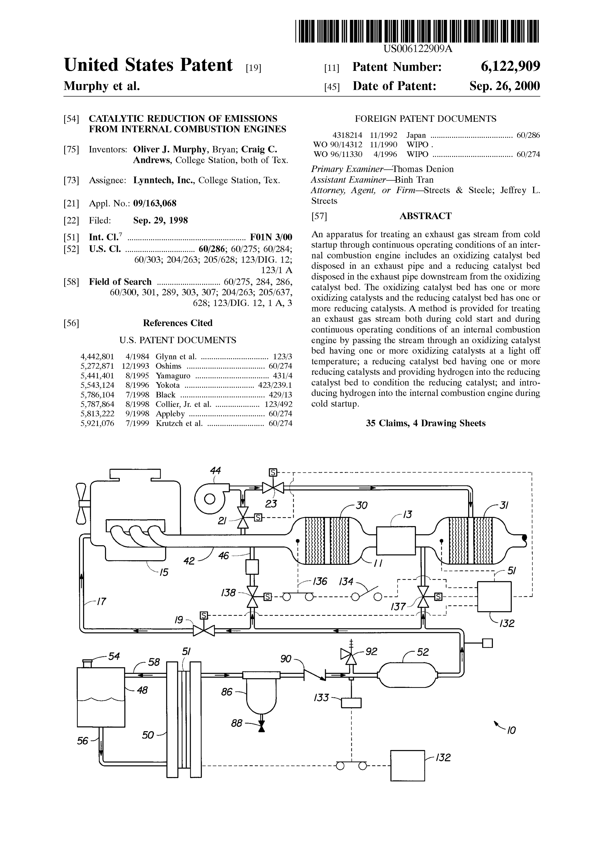
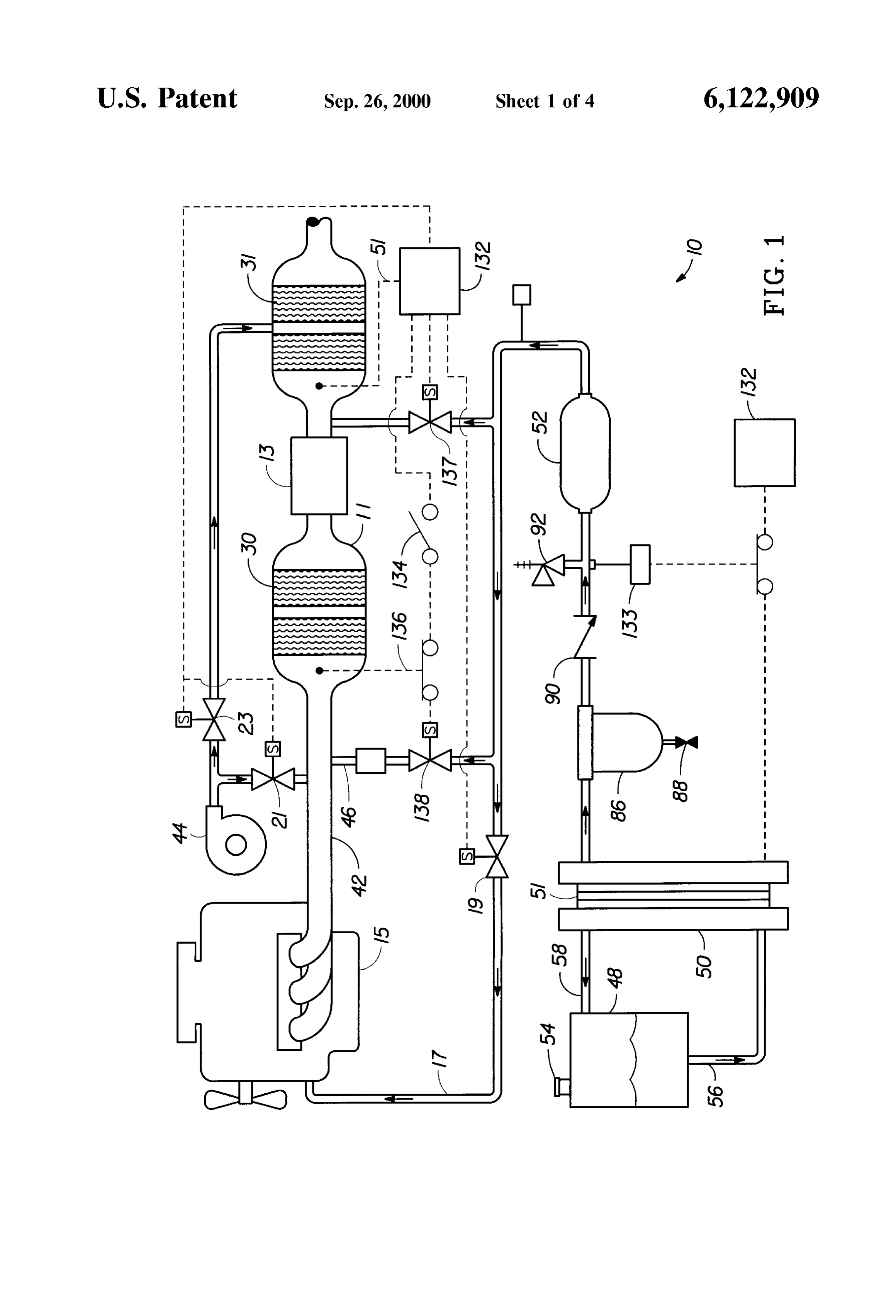
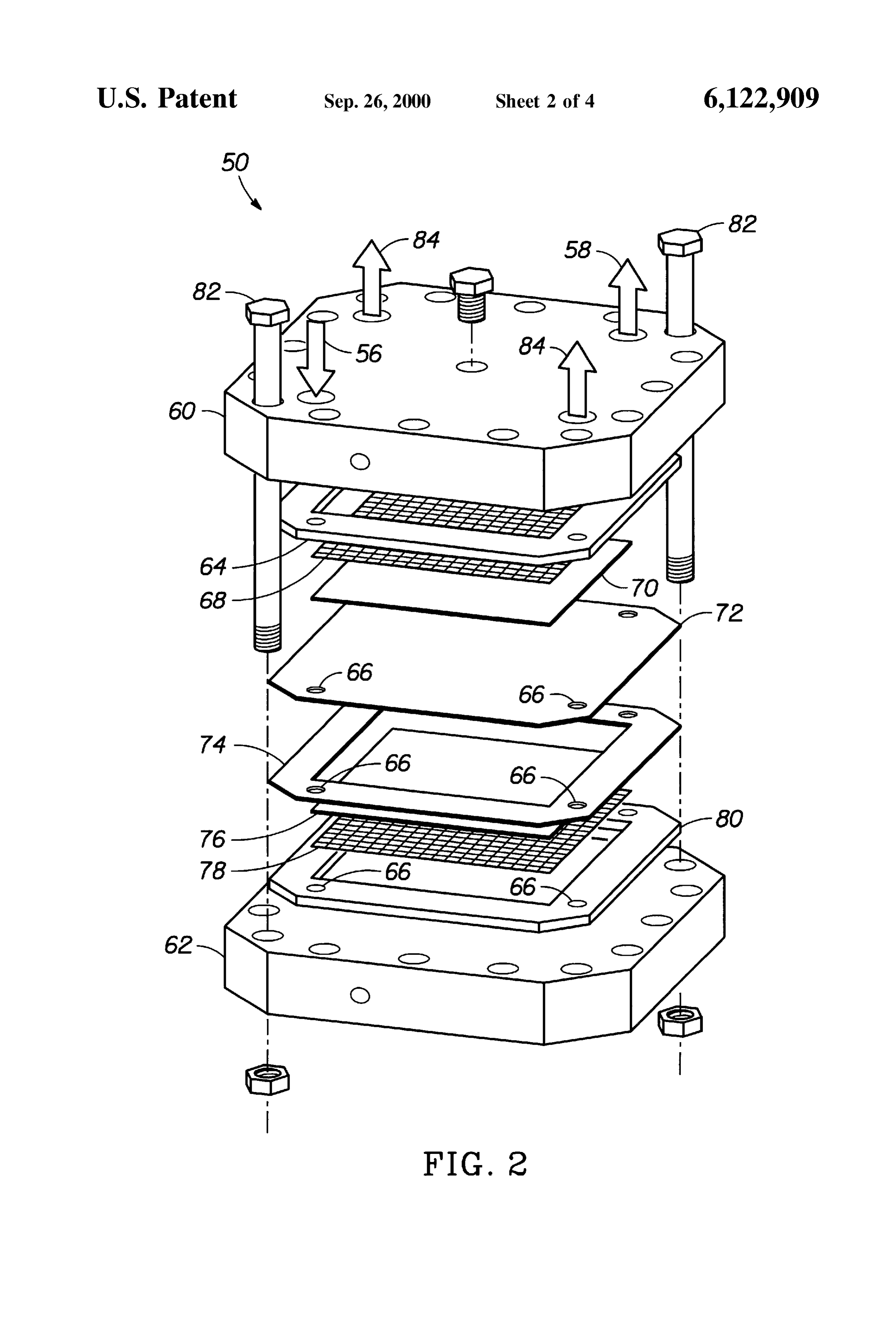
typical embodiments of this invention and are therefore not In another aspect of the present invention, an electrolyzer to be considered limiting of its Scope, for the invention may is used to produce hydrogen on demand, on board the admit to other equally effective embodiments. vehicle or engine Such that the current applied to the FIG. 1 is a Schematic diagram of the apparatus of the electrolyzer is increased to increase hydrogen production as present invention for catalytically reducing emissions from the load on the engine increases. Thus, as the amount of internal combustion engines, exhaust produced increases, more current is applied to the FIG. 2 is an exploded view of an electrolyzer that may be electrolyzer to increase hydrogen production accordingly. employed in the present invention; The ability to generate and Store hydrogen on board and FIG. 3 is a Schematic of a hydrogen capturing and on demand avoids most user maintenance requirements of handling detail used with the System of the present inven other Systems. The hydrogen generation, Storage, and deliv tion.
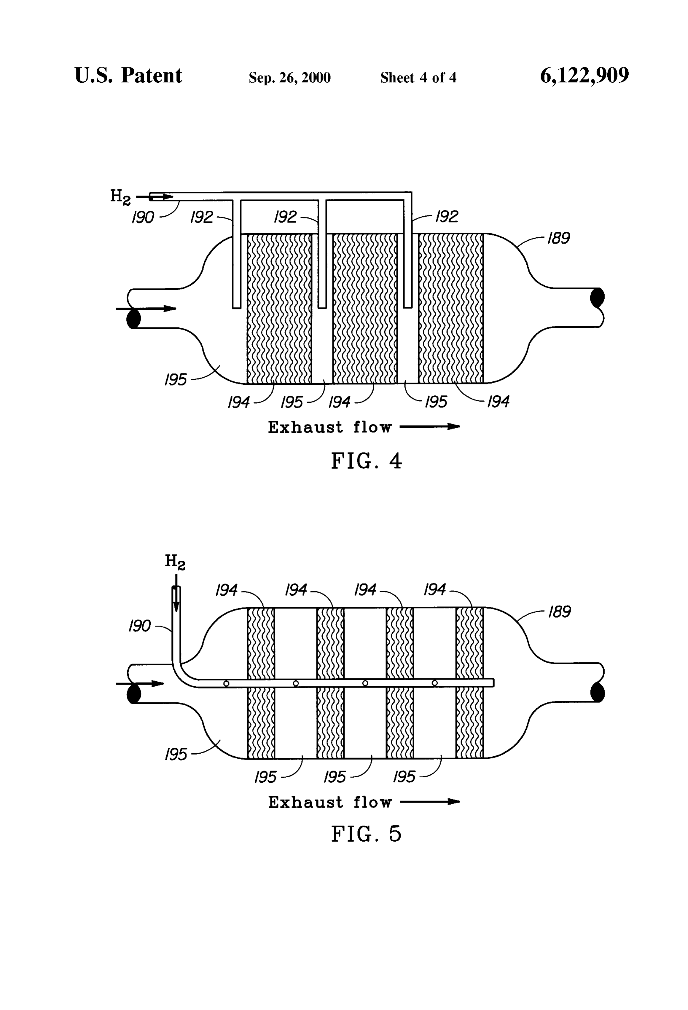
ery System described in the 024 application uses a proton
FIGS. 4 and 5 are catalyst monoliths having a hydrogen exchange membrane (PEM) electrolyzer to split water into distributor. hydrogen and oxygen. AS the hydrogen gas forms, it is compressed by the electrolyzer with efficiencies approach
DETAILED DESCRIPTION OF THE ing theoretical values and without any moving or wearing INVENTION components. It is not necessary to draw power from a The present invention relates to a proceSS for catalytically battery, e.g., a starting, lighting, and ignition (SLI) battery, converting HCs, CO, and NO in stationary and mobile Since the electrolysis process, for the replacement of hydrogen, preferably does not begin until the engine has
Sources Such as boilers, Smelters, diesel generators, jet reached operating temperature. The technical advantages of engines, gas turbine engines, automobiles, and trucks under cold Start and during continuous operating conditions. More 25 this system include, but are not limited to: (i) hydrogen is Specifically, the proceSS involves introducing hydrogen gas generated from a Small amount of water; and (ii) there are no and a Source of oxygen gas, if needed, into an exhaust Stream moving parts or wearing components. The electrolyzer Sys upstream of an oxidation catalyst to bring the oxidation tem does not require any modifications to existing engines or catalyst to its light off temperature quickly, thus enhancing vehicles and retrofitting can be cost-effectively accom the catalytic oxidation of HCs and CO into C0 and H2O. plished. equipment
The electrolyzer is scalable to vehicles or heavy of any size, ranging from Small generators to
Simultaneously, hydrogen gas is introduced upstream of a reducing catalyst to catalytically reduce NO into harmless engines rated at thousands of kilowatts. H2O and N, where the reducing catalyst is located down Another aspect of the present invention relates to decreas Stream of the oxidizing catalyst. ing HC, CO and NO emissions by injecting hydrogen and More specifically, the invention relates to a System for 35 a Source of oxygen, if needed, into an oxidizing catalytic cleaning up lean burn exhaust that is applicable to a “lean converter catalyst prior to, during, and after Startup to heat the burn engine' which uses a dilute air-fuel mixture in order to oxidizing injecting hydrogen to an optimum catalytic temperature and into a reducing catalytic converter to improve fuel economy, as well as a diesel engine, a hydro gen engine and a Stirling engine (an external-combustion condition the reducing catalyst in the reducing catalytic engine) and which is capable of effectively reducing and 40 converter. Conditioning of the catalyst as referred to herein cleaning up nitrogen oxides in the exhaust irrespective of its includes heating, cleaning, and/or activating the catalyst as concentration of oxygen gas without impairing the good fuel well as Saturating the catalyst and the catalyst Support economy of those engines. material with hydrogen. Since a muffler is usually disposed One aspect of the present invention provides a System that in a tailcooled, pipe of an exhaust conduit, the exhaust gas may be removes HCs, CO and NO emitted from a stationary or 45 over conditions, particularly during very cold weather before flowing into the reducing catalytic con mobile internal combustion engine under cold Start and Verter.
during continuous operating conditions by providing tem porally and Spatially a hydrogen enriched oxidizing envi Conventional three-way catalysts and conventional ronment and a hydrogen enriched reducing environment. Cu/Zeolite-type lean NOx catalysts using HC to reduce NOX The System includes a reducing catalytic converter having at 50 show activity in a temperature range above 300-400 C. least one monolith that is coated with a catalyst Suited for and are therefore not Suitable for use in the exhaust pipe near reducing NO and an oxidizing catalytic converter having at the muffler. As discussed above, however, when NOx reduc least one monolith coated with a catalyst Suitable for oxi tion is effected by H instead of by HC, NOx purification at dizing HC and CO. Hydrogen gas is injected into the exhaust low temperatures is possible. The reducing catalyst can be pipe upstream of the oxidizing monolith prior to, during and 55 maintained in a temperature range of from 100-300 C., after Start up to heat the catalyst to a light off temperature. preferably between 120-260 C., and most preferably A Source of oxygen may also be provided to the oxidizing between 125-200 C. It is important to note that the catalyst. When oxygen-rich fuel mixtures are used, no temperature of the reducing catalyst should not fall below oxygen is needed for the oxidizing catalyst. The exhaust about 100° C., because water vapor in the exhaust stream stream then enters the oxidizing monolith where HCs and 60 will convert to liquid form and Saturate the Zeolite, alumina, CO are oxidized and is passed to the reducing monolith Silica or other Support for the catalyst, thus reducing the where hydrogen gas is introduced into the reducing mono effectiveness of the catalyst.
lith. The hydrogen is preferably generated on board the The present invention makes it possible to maintain the vehicle or other equipment Securing the engine. Continuous reducing catalyst at low temperatures. With a conventional hydrogen production may be maintained on board the 65 emission removal apparatus, it would be necessary to oper vehicle or Stationary engine with the use of an electrolyzer, ate the catalyst at higher temperatures because HCS and CO such as the proton exchange membrane (PEM) electrolyzer could be oxidized off and thus would not be allowed to Stick
Page 9
to and eventually poison the reducing catalyst. In the present Spective of the presence or absence of O2 from the exhaust invention, HCs and CO are removed by the oxidizing or of the concentration of O in the exhaust), NOx can be catalyst prior to, during, and after Startup of the engine. The reduced with the catalyst so that the best performance of the removal of these HCs and CO prior to, during, and after engine and fuel can be selected without considering the Startup of the engine greatly increases the efficiency of the conditions for reducing the NOx content. reducing catalyst by allowing it to be maintained at tem Both the reducing and oxidizing catalytic converters peratures that are optimal for hydrogen initiated reduction of described above may have more than one catalytic monolith NOX. Segment within a single housing. Multiple monoliths will The reaction between NOx and hydrogen by nature pro increase the amount of HC and CO oxidized as well as the duces heat, therefore another aspect of the present invention amount of NO reduced. Hydrogen can be introduced to all is directed to withdrawing the heat from the reducing or Some of the monolith Segments in each catalytic con catalytic converter. The reducing catalyst monolith is Verter.
equipped with cooling fins and/or a typical tube-in-shell heat On-board, on-demand electrochemically generated eXchanger to remove the heat from the reducing catalyst. hydrogen greatly simplifies and readily facilitates the use of The monolith would then have catalyst on the tube side and 15 hydrogen as a controlled chemical additive to exhaust air flow on the shell side for cooling the monolith. The streams leading to the removal of CO, HC and NO emis exhaust Stream would pass through the tube Side of the heat Sions. An automated water clectrolyzer Subsystem for the eXchanger and contact the catalyst as it passes through the on-demand production of hydrogen can be easily integrated monolith. Air from an auxiliary air pump may be cooled and with various engines, e.g., diesel generators. Such a water circulated through the heat eXchanger but not into direct electrolyzer Subsystem has unique features that make it contact with the catalyst itself. Alternatively, Suitable metal ideally Suited for the proposed application. These include: (i) lic cooling fins may be used to withdraw heat from the an instantaneous response time for initiating hydrogen gen reducing catalytic converter. A temperature Sensor can be eration; (ii) excellent load following capabilities enabling a located in or near the reducing monolith to monitor the rapid response to changing engine operating conditions; (iii) temperature and initiate pulsed hydrogen flow when the 25 the capability of delivering pure hydrogen gas at pressures monolith reaches a certain critical temperature. Reducing or up to 1000 psi, if desired; and (iv) facilitates pressurized restricting the hydrogen flow temporarily will allow the Storage of hydrogen gas on-site, if needed, when carrying monolith to cool and the NOx reduction will continue at out maintenance and repairs. The water electrolyzer can be least to Some extent with residual hydrogen present in the fully automated, thus precluding the need for manual atten catalyst Support material. tion or operation.
The lean burn engine and the diesel engine are basically The electrolyzer can be run by Supplying a Small portion the same in that the exhaust contains excess O and the of the electrical energy generated by the combustion engine concentration O in the exhaustincreases as the air/fuel ratio (diesel generator, automobile, gas turbine engine, etc.). It increases. The catalyst for reducing and cleaning up the NOX should also be noted that Stationary engines or other Sources in Such O containing exhaust is called a “lean catalyst”, 35 of exhaust gas may utilize other Sources of electricity. The which is often Selected from among noble metal based hydrogen gas generated by the electrolyzer can be fed catalysts Such as those Supported on Zeolite. The reaction directly to the flue gas or exhaust gas Stream and passed over between HC and NOx occurs mainly in the high-temperature an oxidizing and/or reducing catalyst. The amount of hydro (>350° C.) range. On the other hand, in the low-temperature gen Supplied can be regulated electronically in real time by (<300° C.) range, a reaction for reducing NOx with H. 40 Simply varying the current applied to the electrolyzer. occurs, enabling the cleanup of NOX. Another type of A hydrogen Storage vessel may be used to Supply hydro catalyst for reducing and cleaning up the NOX in the O gen to the oxidizing and reducing catalytic converters for containing exhaust is also called a “lean NOX catalyst”, cold Start operations to increase the temperature of the which is Selected from among those catalysts which Support oxidizing catalytic converter as described in application noble metals such as Pt. If CO or active HC is present in 45 024 and to condition the reducing catalytic converter. The gases that flow into the reducing catalytic monolith, those hydrogen is Stored under pressure and is injected into the gases will cover the Surface of the catalyst through oxidizing catalytic converter, along with air, if needed, adsorption, thereby blocking the reaction of NOx reduction preferably delivered using a Secondary air pump, to heat the with H. However, with the present invention, the HCs and oxidizing catalyst. Hydrogen may be fed from the Storage CO are removed prior to, during, and after Startup of the 50 vessel to the reducing catalyst Simultaneously or after the engine in the oxidizing catalytic converter, Such that the engine warms up. The clectrolyzer can continue to run, both temperature of the reducing catalyst can be maintained to provide a Sufficient Stream of hydrogen to the reducing between 100-300° C. with little concern for HC and CO catalytic converter to reduce the NO emissions and to adsorption on the reducing catalyst in the reducing catalytic replenish the Stored hydrogen Supply. COnVerter. 55 In addition, the Stored hydrogen may be injected Simul Conventionally, the catalyzer is installed near the exhaust taneously into the engine as a Substitute for fuel on Start up. manifold on the engine, So the catalyst is exposed to the The hydrogen is preferably injected into the engine for up to exhaust which is as hot as 800-900 C. at maximum. In one minute at Start up, most preferably about 10–15 Seconds, addition, the exhaust from the lean burn engine which uses before the proscribed fuel is fed to the engine. Hydrogen an air-fuel mixture leaner than the Stoichiometric ratio is 60 addition to the oxidizing catalytic converter is preferably Substantially free from H2. Under these circumstances, it has begun at Startup and continued until the catalyst reaches a been impossible in the prior art to utilize the characteristics light off temperature in accordance with the cold Start of the catalyst that is active at lower temperatures. procedures outlined above. Hydrogen is also delivered to the In contrast, the method and apparatus of the present reducing catalyst to condition the reducing catalyst before invention have the advantage that whether the engine is 65 the NOx production becomes substantial. This system can be operated at an air/fuel ratio richer or leaner than the Sto adapted to work with engines that use gasoline, diesel, ichiometric value or at the Stoichiometric ratio (i.e., irre gasohol, methanol, natural gas or other fuels.
Page 10
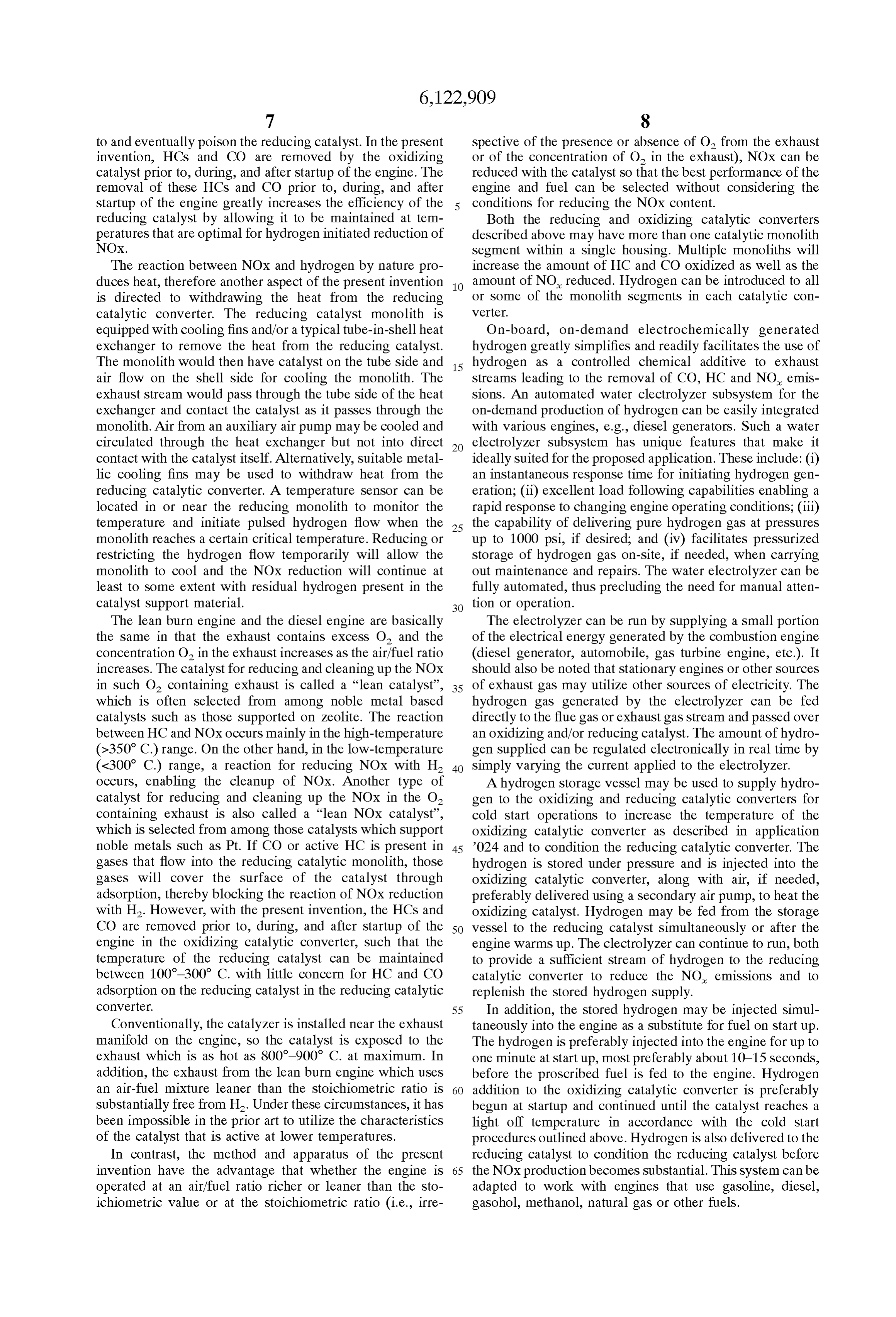
Hydrogen can be delivered intermittently to the reducing an oxidizing catalytic converter 11 located in an exhaust line catalyst to increase the amount of NOX reduced. A compo 42 from a vehicle's engine 15 exhaust manifold, a reducing nent which occludes nitrogen oxides is added to the catalyst catalytic converter 31 in communication with the exhaust for reducing nitrogen oxides while the feeding of the reduc line 42 and an optional muffler 13 in the exhaust line 42 in ing agent (H) is Suspended. This helps increase the con between the oxidizing and reducing catalytic converters as centration of the NOx in the catalyst. If the hydrogen is shown. The exhaust line 42 is provided with air, if required, delivered in pulses, the temperature of the reducing catalyst from an air pump 44 and hydrogen from a hydrogen inlet goes down, further increasing the overall reduction of NOX. line 46. The air pump could be any Suitable air Source, Such The component used to occlude NOx, can be selected from as a receiver, for injecting air into the exhaust line at Suitable alkali metals, alkaline earth metals and mixtures thereof and preSSure and Volumetric flow rate to achieve the ideal loaded on the reducing catalyst. air/hydrogen ratio mixture for heating the oxidizing catalyst in the converter 11.
Suitable reducing catalysts that are useful in hydrogen The hydrogen Supply System of the invention generally initiated catalytic reduction of NO, include noble metal includes a water reservoir 48, an electrolyzer 50, and an catalysts such as Pt, Ru, and metal alloys based on Pt and optional hydrogen Storage cylinder 52. AS shown in FIG. 1, Ru. It is preferred that the noble metal catalysts are highly the electrolyzer 50 may
preferably compromise a plurality of distributed on a carrier having a high Specific Surface area stacked identical cells 51. The reservoir 48 serves both as a (greater than 100 m/g) Such as alumina, silica, or Zeolite. water reservoir and as a separator for oxygen and water. The Other Zeolite-based catalysts may be useful for reducing reservoir 48 may be a vehicle's windshield washer fluid NOX such as Cubased ZSM-5 catalyst. ZSM-5 reduces NO Storage container, but is preferably a dedicated Separator under a wider range of temperatures in a net oxidizing allowing collection and Storage of oxygen via port 54. Water stream, even with water and SO in the stream. Therefore, flows by gravity drain or is pumped from the reservoir 48 to Zeolite catalysts appear to be highly Suitable for lean bum the electrolyzer 50 via a drain line 56. As the electrolyzer diesel and jet engines. In addition to Cu-ZSM-5, it is produces hydrogen and oxygen, the oxygen and entrained believed that Indium or Gallium based ZSM-5 catalysts may 25 water flows naturally back to the reservoir 48 via a return also be useful catalysts for NOx reduction. line 58.
It is believed that the Pt/TiO catalyst for NO conversion The next major component of the hydrogen Source is the may be Suitable for gasoline engines, but may not be as electrolyzer 50, shown in greater detail in FIG. 2. In the effective in diesel-powered engines, which operate under following description of the electrolyzer 50, the materials of exceSS air conditions, without a means for removing exceSS construction referred to as "preferred” are the materials used oxygen prior to reducing the NO. However, Pt/TiO, and in a test device to prove that the electrolyzer 50 works for its Ru?TiO2 catalysts, along with the aforementioned catalysts intended purpose. In commercial production models of the may be useful in any type of engine by adjusting the present invention, where possible, less expensive materials concentration ratioS of the catalyst to optimize the use of will be used throughout, Such as carbon Steel for titanium hydrogen as a reactant and reduce the likelihood that the 35 where possible, and plastic Such as polypropylene where hydrogen will be converted to water as a result of combining heat and StreSS will permit the use of Such material. with oxygen. The electrolyzer 50 may be referred to herein as a proton A cost-effective, Safe, reliable and energy-efficient tech exchange membrane (PEM) electrolyzer 50. The proton nology for on-site, on-demand generation of pure hydrogen eXchange membrane itself may prove corrosive in this is provided by the electrolyzer described in application 40 environment in contact with certain Substances, thus requir number 024. The electrolyzer, when supplied with electrical ing the careful Selection of the material of construction of the energy, Splits water into hydrogen and oxygen. In a proton electrolyzer. For example, the PEM should only contact exchange-membrane (PEM) electrolyzer, protons are trans carbon or graphite. However, those of skill in the art will ported through the solid membrane electrolyte from the readily recognize where leSS exotic materials than those anode to the cathode. At the Surface of the cathodic 45 listed in the following discussion that are located away from electrocatalyst, the protons recombine with electrons from the PEM material itself and the oxygen electrode catalyst an external circuit and are liberated as hydrogen gas mol can be readily employed without penalty. For example, ecules. graphite will be the material of choice in certain Structural The lifetime of PEM water electrolyzers has been dem elements, and not Some obvious candidates Such as copper, onstrated to be in excess of 14 years and projected to be over 50 aluminum, or iron, which can corrode thus forming ions that 30 years, depending on the operating conditions. Water can poison the oxygen and/or hydrogen electrode catalysts. electrolyzers have been employed in Several applications, Now referring to FIG. 2, the PEM electrolyzer 50 is especially, where reliability and purity of the gases produced shown as a cell Stack including a pair of endplates 60 and 62. are the primary concerns. The water electrolyzer disclosed The endplates 60 and 62 are preferably titanium and mea herein is extremely effective in rapidly preheating the oxi 55 sure 4.2"x4.2"x24". Adjacent the top endplate 60 is an anodic dizing catalytic converter of gasoline powered vehicles or cell frame 64. The cell frame 64 is preferably a carbon other engines. The electrochemically generated hydrogen fiber-filled TEFLON sheet, sold under the trademark and a Source of Secondary air if required are introduced ZYMAXX by Du Pont. The cell frame 64 retains a 1:1 molar directly upstream of the oxidizing catalytic converter and the ratio of iridium and ruthenium dioxides (IrO/RuO2) as the converter is rapidly brought to operating temperature by the 60 anodic electrocatalyst. The cell frame 64 also includes a catalytic combination reaction. With an air flow rate of 90 plurality of flow ports 66 to permit the Supply of reactant liters per minute mixed with 11 vol% hydrogen, the front (water) and/or removal of electrolysis product (oxygen gas). face of a catalyst-coated ceramic monolith reached 400 C. Below the cell frame 64 is an expanded titanium metal within two seconds and 9% of the ceramic was heated to current collector (flow field) 68, preferably 25 Ti 40–3/32 400 C. in three seconds. 65 from Exmet Corp. An anode substrate 70 is preferably a FIG. 1 shows a system 10 of the present invention porous titanium plate measuring 2.49"x2.49"x0.05". Below installed on a vehicle exhaust System. The vehicle includes the anode substrate 70 is a proton exchange membrane 72,
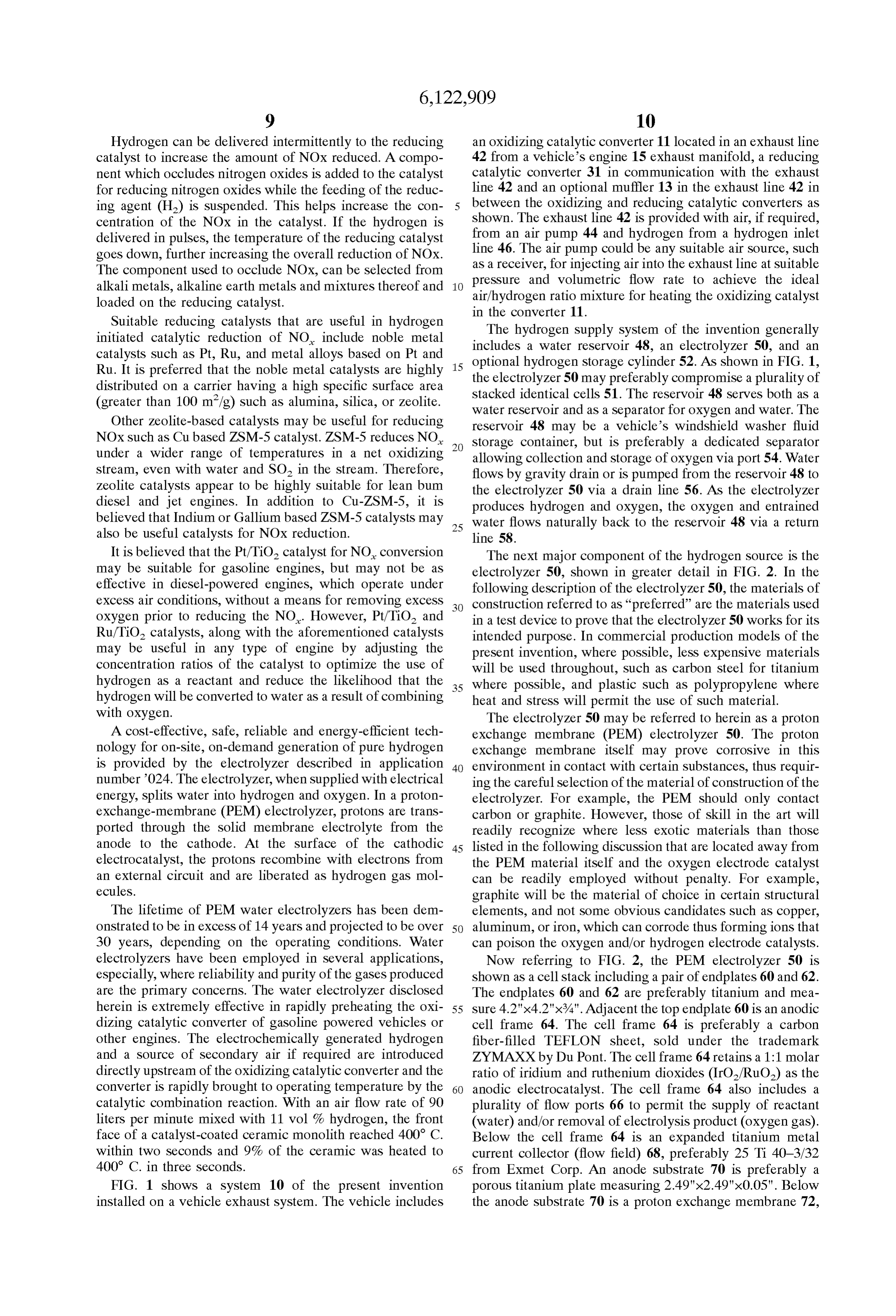
Page 11
cut from a sheet of NAFION 117 from Du Pont which serves hydrogen generated can be accumulated at pressure. Prior to as a solid electrolyte material and which is 175 um thick. operation, the System of FIG.3 permits purging with an inert FIG. 2 depicts a gasket 74, one of perhaps Several gas, Such as nitrogen. For Safety reasons, all air is first installed where required. Gaskets 74 are stamped from 0.033 removed from the System by attaching a nitrogen gas inch thick fluorosilicone sheet (Viton) and from 0.005 inch feedline at a purge gas inlet 94 downstream of a check valve 90. During the purging operation, the hydrogen Storage thick unsintered PTFE sheet. The electrolyzer 50 further cylinder or vessel 52, Such as a metal hydride vessel, is includes a cathode Substrate 76 like the anode Substrate 70 and an expanded titanium flow field. detached at a quick disconnect 96. This operation effectively seals both the vessel 52 and a gas line 98, to keep the purge
Finally, the PEM clectrolyzer 50 includes a cathodic cell gas out of the vessel 52. The remainder of the system is then frame 80 formed of polychlorotrifluorethylene (PCTFE) purged from the purge gas inlet 94 through a back preSSure sheet, sold under the trademark KEL-F by Afton Plastics. regulator 100.
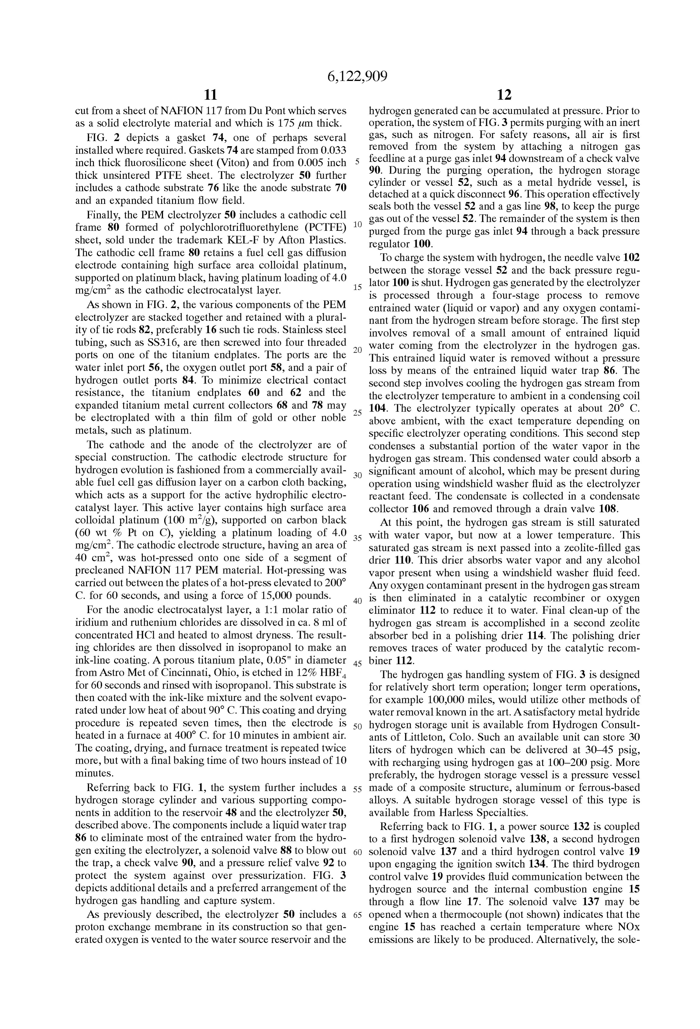
The cathodic cell frame 80 retains a fuel cell gas diffusion To charge the system with hydrogen, the needle valve 102 electrode containing high Surface area colloidal platinum, between
Supported on platinum black, having platinum loading of 4.0 lator 100 the is
Storage vessel 52 and the back preSSure regu shut. Hydrogen gas generated by the electrolyzer mg/cm as the cathodic electrocatalyst layer. 15 is processed through a four-stage process to remove
As shown in FIG. 2, the various components of the PEM entrained water (liquid or vapor) and any oxygen contami electrolyzer are Stacked together and retained with a plural nant from the hydrogen Stream before Storage. The first Step ity of tie rods 82, preferably 16 Such tie rods. Stainless steel involves removal of a Small amount of entrained liquid tubing, such as SS316, are then screwed into four threaded water coming from the electrolyzer in the hydrogen gas. ports on one of the titanium endplates. The ports are the This entrained liquid water is removed without a preSSure water inlet port 56, the oxygen outlet port 58, and a pair of loss by means of the entrained liquid water trap 86. The hydrogen outlet ports 84. To minimize electrical contact Second Step involves cooling the hydrogen gas Stream from resistance, the titanium endplates 60 and 62 and the the electrolyzer temperature to ambient in a condensing coil expanded titanium metal current collectors 68 and 78 may 104. The electrolyzer typically operates at about 20 C. be electroplated with a thin film of gold or other noble 25 above ambient, with the exact temperature depending on metals, Such as platinum. Specific electrolyzer operating conditions. This Second Step The cathode and the anode of the clectrolyzer are of condenses a Substantial portion of the water vapor in the Special construction. The cathodic electrode Structure for hydrogen gas Stream. This condensed water could absorb a hydrogen evolution is fashioned from a commercially avail Significant amount of alcohol, which may be present during able fuel cell gas diffusion layer on a carbon cloth backing, operation using windshield washer fluid as the electrolyzer which acts as a Support for the active hydrophilic electro reactant feed. The condensate is collected in a condensate catalyst layer. This active layer contains high Surface area collector 106 and removed through a drain valve 108. colloidal platinum (100 m/g), supported on carbon black At this point, the hydrogen gas Stream is still Saturated (60 wt % Pt on C), yielding a platinum loading of 4.0 35 with water vapor, but now at a lower temperature. This mg/cm. The cathodic electrode structure, having an area of Saturated gas Stream is next passed into a Zeolite-filled gas 40 cm, was hot-pressed onto one side of a segment of drier 110. This drier absorbs water vapor and any alcohol precleaned NAFION 117 PEM material. Hot-pressing was Vapor present when using a windshield washer fluid feed. carried out between the plates of a hot-press elevated to 200 Any oxygen contaminant present in the hydrogen gas Stream C. for 60 seconds, and using a force of 15,000 pounds. 40 is then eliminated in a catalytic recombiner or oxygen For the anodic electrocatalyst layer, a 1:1 molar ratio of eliminator 112 to reduce it to water. Final clean-up of the iridium and ruthenium chlorides are dissolved in ca. 8 ml of hydrogen gas Stream is accomplished in a Second Zeolite concentrated HCl and heated to almost dryness. The result absorber bed in a polishing drier 114. The polishing drier ing chlorides are then dissolved in isopropanol to make an removes traces of water produced by the catalytic recom ink-line coating. A porous titanium plate, 0.05" in diameter 45 biner 112.
from Astro Met of Cincinnati, Ohio, is etched in 12% HBF The hydrogen gas handling System of FIG. 3 is designed for 60 seconds and rinsed with isopropanol. This substrate is for relatively short term operation; longer term operations, then coated with the ink-like mixture and the Solvent evapo for example 100,000 miles, would utilize other methods of rated under low heat of about 90° C. This coating and drying water removal known in the art. A Satisfactory metal hydride procedure is repeated Seven times, then the electrode is 50 hydrogen Storage unit is available from Hydrogen Consult heated in a furnace at 400° C. for 10 minutes in ambient air. ants of Littleton, Colo. Such an available unit can store 30 The coating, drying, and furnace treatment is repeated twice liters of hydrogen which can be delivered at 30-45 psig, more, but with a final baking time of two hours instead of 10 with recharging using hydrogen gas at 100-200 psig. More minutes. preferably, the hydrogen Storage vessel is a pressure vessel Referring back to FIG. 1, the system further includes a 55 made of a composite Structure, aluminum or ferrous-based hydrogen Storage cylinder and various Supporting compo alloys. A Suitable hydrogen Storage vessel of this type is nents in addition to the reservoir 48 and the electrolyzer 50, available from Harless Specialties. described above. The components include a liquid water trap Referring back to FIG. 1, a power source 132 is coupled 86 to eliminate most of the entrained water from the hydro to a first hydrogen Solenoid valve 138, a Second hydrogen gen exiting the electrolyzer, a solenoid valve 88 to blow out 60 Solenoid valve 137 and a third hydrogen control valve 19 the trap, a check valve 90, and a pressure relief valve 92 to upon engaging the ignition Switch 134. The third bydrogen protect the System against over pressurization. FIG. 3 control valve 19 provides fluid communication between the depicts additional details and a preferred arrangement of the hydrogen Source and the internal combustion engine 15 hydrogen gas handling and capture System. through a flow line 17. The Solenoid valve 137 may be As previously described, the electrolyzer 50 includes a 65 opened when a thermocouple (not shown) indicates that the proton eXchange membrane in its construction So that gen engine 15 has reached a certain temperature where NOx erated oxygen is vented to the water Source reservoir and the emissions are likely to be produced. Alternatively, the Sole
Page 12
noid valve 137 may be opened at a predetermined period of 3. The System of claim 1, wherein the reducing catalyst time after ignition of the engine. In order to control the flow bed is conditioned by opening the Second hydrogen control of hydrogen to the oxidizing catalyst, the Solenoid valve 138 valve.
may remain open or be pulsed until the thermocouple 136 4. The System of claim 2, wherein the oxidizing catalyst reads a temperature equal to or greater than the light-off bed is conditioned until reaching a light off temperature. temperature. In another embodiment, the hydrogen outlet 5. The System of claim 1, wherein the reducing catalyst is from the electrolyzer may be provided in direct fluid com conditioned Selectively continuous or discontinuous munication with the reducing catalytic converter instead of throughout operation of the internal combustion engine. passing through the Storage vessel 52. 6. The System of claim 1, wherein the oxidizing catalyst Air from the air pump 42 may be delivered to a tube-in bed is Selected from a two-way catalyst and a three-way shell heat eXchanger in communication with the reducing catalyst.
catalyst in order to cool the catalyst. Temperature Sensor 51 7. The System of claim 1, further comprising hydrogen can be located in the reducing monolith 31 Similar to delivery ports in communication with one or more regions of thermocouple 136. When the temperature in the reducing the reducing catalyst bed.
monolith approaches a critical high temperature (above the 15 8. The system of claim 1, wherein the reducing catalyst optimum working temperature set by the operator) air may bed includes essentially no catalyst for oxidizing nitrogen. be circulated through the heat eXchanger to cool the mono 9. The system of claim 1, wherein the source of hydrogen lith. On the other hand, if the temperature falls below 100 includes an on-board electrolyzer. C., air and/or hydrogen can be introduced into contact with 10. The system of claim 9, wherein the on-board electro the reducing catalyst monolith to increase the temperature of lyZer has an anode for producing oxygen, and wherein the the monolith. anode is in fluid communication with the oxygen Source. Also in FIG. 1, the electrolyzer 50 receives power from 11. The system of claim 1, wherein the third control valve the Source 132 when the hydrogen pressure in or near the cold provides hydrogen to the internal combustion engine during hydrogen Storage vessel 52, as indicated by pressure Sensor 25 Start.
133, falls below a setpoint pressure between about 50 psig 12. A method for preventing and treating exhaust gas from and about 400 psig. It should be recognized that the power an internal combustion engine, comprising: to the electrolyzer 50 is turned off when the pressure exceeds Supplying hydrogen fuel to an internal combustion engine a high preSSure Setpoint, Such as 400 psig. It should also be during cold Start;
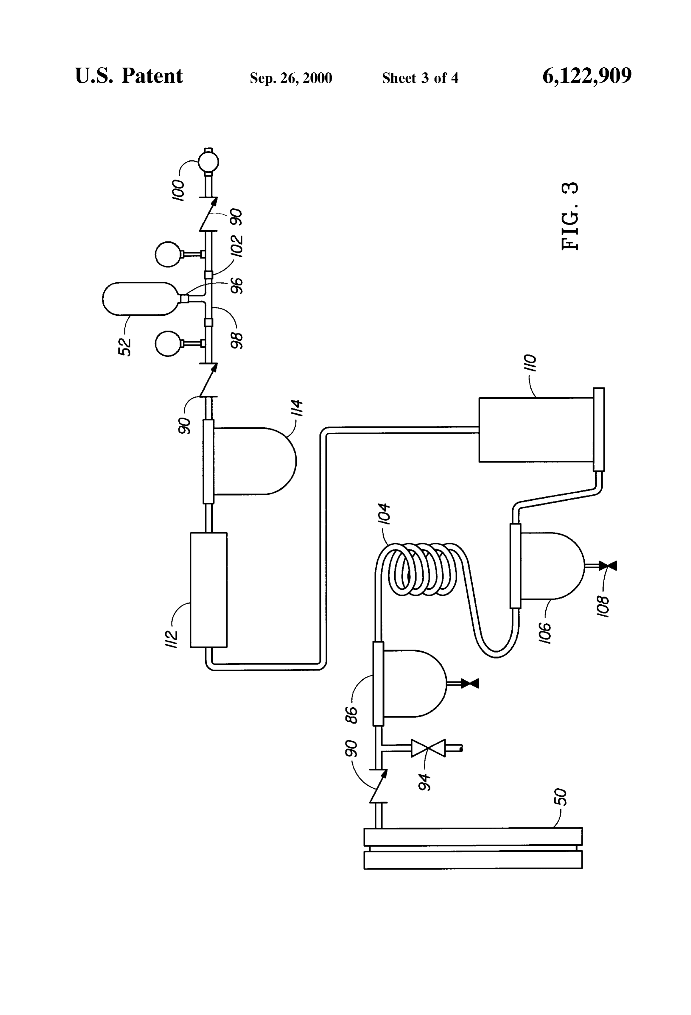
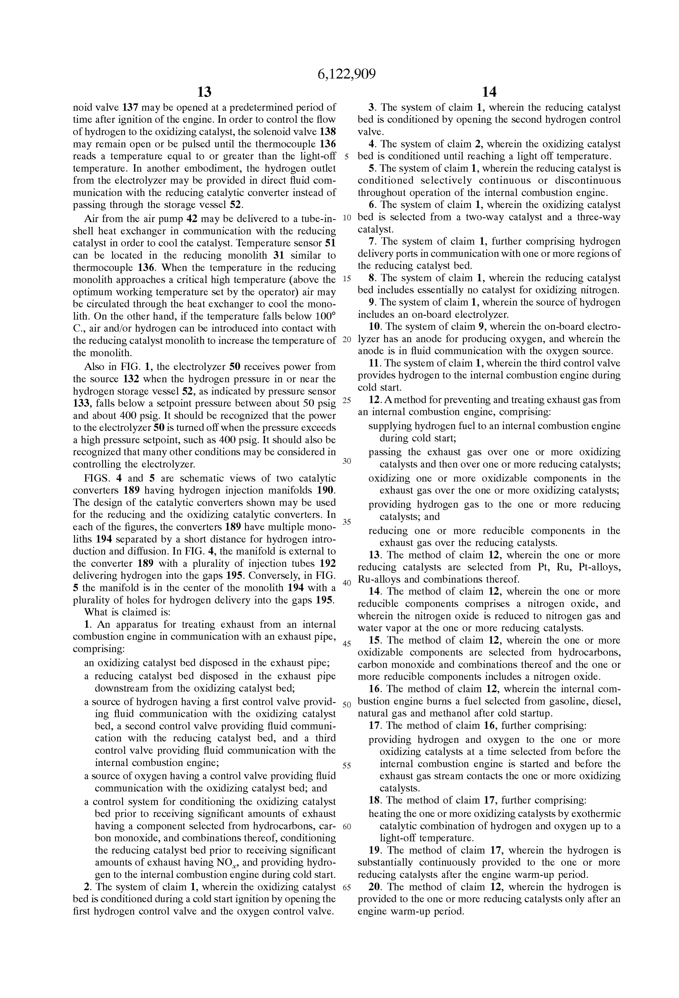
recognized that many other conditions may be considered in passing the exhaust gas over one or more oxidizing controlling the electrolyzer. catalysts and then over one or more reducing catalysts, FIGS. 4 and 5 are schematic views of two catalytic oxidizing one or more oxidizable components in the converters 189 having hydrogen injection manifolds 190. exhaust gas over the one or more oxidizing catalysts, The design of the catalytic converters shown may be used providing hydrogen gas to the one or more reducing for the reducing and the oxidizing catalytic converters. In 35 catalysts, and each of the figures, the converters 189 have multiple mono reducing one or more reducible components in the liths 194 separated by a short distance for hydrogen intro exhaust gas over the reducing catalysts. duction and diffusion. In FIG. 4, the manifold is external to 13. The method of claim 12, wherein the one or more the converter 189 with a plurality of injection tubes 192 reducing catalysts are Selected from Pt, Ru, Pt-alloys, delivering hydrogen into the gaps 195. Conversely, in FIG. Ru-alloys and combinations thereof. 5 the manifold is in the center of the monolith 194 with a 40 14. The method of claim 12, wherein the one or more plurality of holes for hydrogen delivery into the gaps 195. reducible components comprises a nitrogen oxide, and What is claimed is: wherein the nitrogen oxide is reduced to nitrogen gas and 1. An apparatus for treating exhaust from an internal water vapor at the one or more reducing catalysts. combustion engine in communication with an exhaust pipe, 45 15. The method of claim 12, wherein the one or more comprising: oxidizable components are Selected from hydrocarbons, an oxidizing catalyst bed disposed in the exhaust pipe; carbon monoxide and combinations thereof and the one or a reducing catalyst bed disposed in the exhaust pipe more reducible components includes a nitrogen oxide. downstream from the oxidizing catalyst bed; 16. The method of claim 12, wherein the internal com a Source of hydrogen having a first control valve provid 50 bustion engine burns a fuel Selected from gasoline, diesel, ing fluid communication with the oxidizing catalyst natural gas and methanol after cold Startup.
bed, a Second control valve providing fluid communi 17. The method of claim 16, further comprising: cation with the reducing catalyst bed, and a third providing hydrogen and oxygen to the one or more control valve providing fluid communication with the Oxidizing catalysts at a time Selected from before the internal combustion engine; 55 internal combustion engine is Started and before the a Source of oxygen having a control valve providing fluid exhaust gas Stream contacts the one or more oxidizing communication with the oxidizing catalyst bed; and catalysts.
a control System for conditioning the oxidizing catalyst 18. The method of claim 17, further comprising: bed prior to receiving Significant amounts of exhaust heating the one or more oxidizing catalysts by exothermic having a component Selected from hydrocarbons, car 60 catalytic combination of hydrogen and oxygen up to a bon monoxide, and combinations thereof, conditioning light-off temperature.
the reducing catalyst bed prior to receiving Significant 19. The method of claim 17, wherein the hydrogen is amounts of exhaust having NO, and providing hydro Substantially continuously provided to the one or more gen to the internal combustion engine during cold Start. reducing catalysts after the engine warm-up period. 2. The System of claim 1, wherein the oxidizing catalyst 65 20. The method of claim 12, wherein the hydrogen is bed is conditioned during a cold Start ignition by opening the provided to the one or more reducing catalysts only after an first hydrogen control valve and the oxygen control valve. engine warm-up period.
Page 13
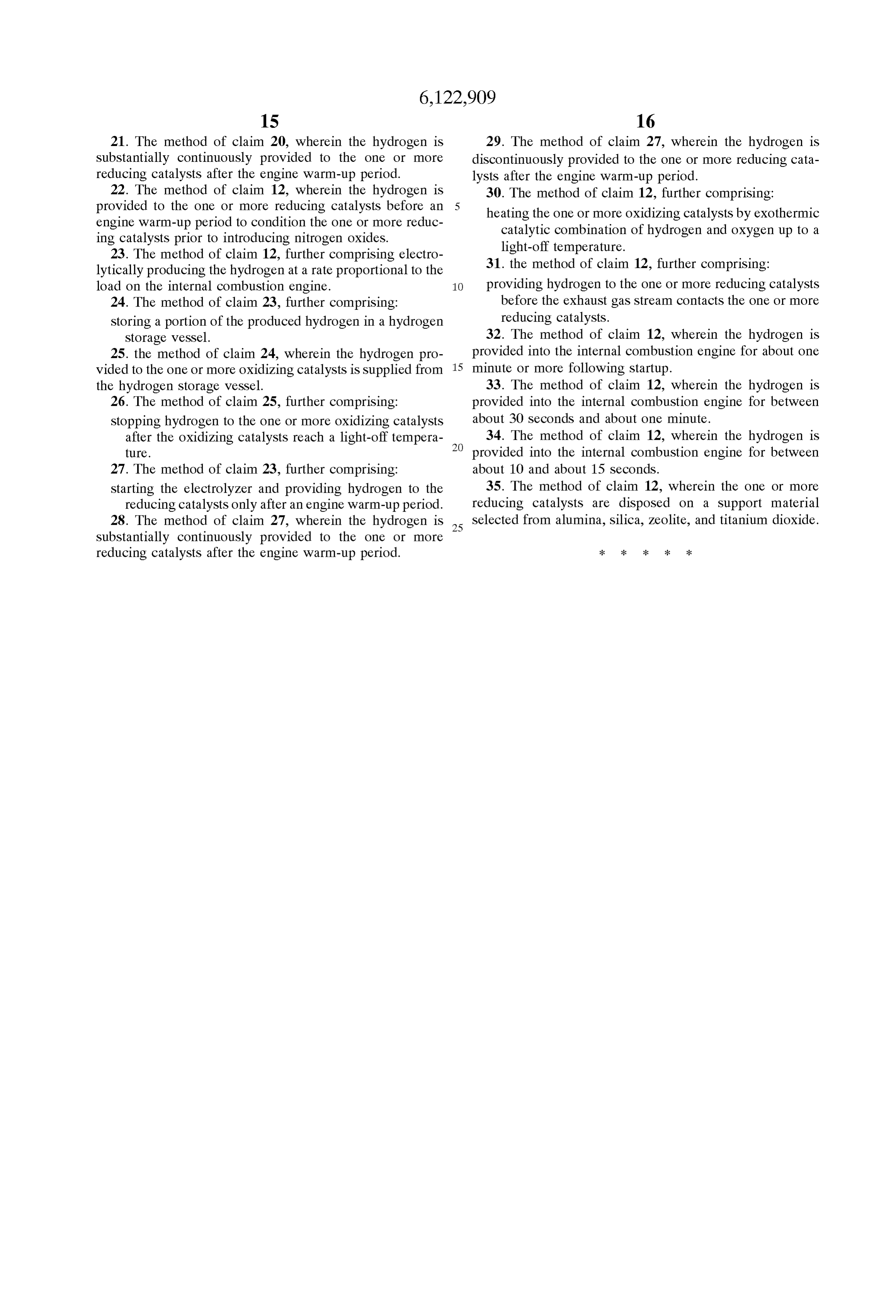
21. The method of claim 20, wherein the hydrogen is 29. The method of claim 27, wherein the hydrogen is Substantially continuously provided to the one or more discontinuously provided to the one or more reducing cata reducing catalysts after the engine warm-up period. lysts after the engine warm-up period. 22. The method of claim 12, wherein the hydrogen is 30. The method of claim 12, further comprising: provided to the one or more reducing catalysts before an heating the one or more oxidizing catalysts by exothermic engine warm-up period to condition the one or more reduc catalytic combination of hydrogen and oxygen up to a ing catalysts prior to introducing nitrogen oxides. light-off temperature.
23. The method of claim 12, further comprising electro 31. the method of claim 12, further comprising: lytically producing the hydrogen at a rate proportional to the load on the internal combustion engine. 1O providing hydrogen to the one or more reducing catalysts 24. The method of claim 23, further comprising: before the exhaust gas Stream contacts the one or more Storing a portion of the produced hydrogen in a hydrogen reducing catalysts.
Storage vessel. 32. The method of claim 12, wherein the hydrogen is 25. the method of claim 24, wherein the hydrogen pro provided into the internal combustion engine for about one Vided to the one or more oxidizing catalysts is Supplied from 15 minute or more following Startup. the hydrogen Storage vessel. 33. The method of claim 12, wherein the hydrogen is 26. The method of claim 25, further comprising: provided into the internal combustion engine for between Stopping hydrogen to the one or more oxidizing catalysts about 30 Seconds and about one minute. after the oxidizing catalysts reach a light-off tempera 34. The method of claim 12, wherein the hydrogen is ture. provided into the internal combustion engine for between 27. The method of claim 23, further comprising: about 10 and about 15 seconds.
Starting the electrolyzer and providing hydrogen to the 35. The method of claim 12, wherein the one or more reducing catalysts only after an engine warm-up period. reducing catalysts are disposed on a Support material 28. The method of claim 27, wherein the hydrogen is 25 Selected from alumina, Silica, Zeolite, and titanium dioxide. Substantially continuously provided to the one or more reducing catalysts after the engine warm-up period. k k k k k
Provenance
- Collection
- Cited prior art
- Original PDF
- patentimages.storage.googleapis.com →
- Filed
- 1998-09-29
- Pages
- 13
- Method
- pdftotext (the PDF's own text layer) + pdftoppm 300dpi page scans
- Source
- Google Patents bibliographic record
- Granted
- 2000-09-26
- Inventors
- Oliver J. Murphy; Craig C. Andrews; LYNNTECH Inc
- Transcribed from
- patentimages.storage.googleapis.com →