patent · US6314732B1
Hydrogen fueled power plant system
13 November 2001
Page 1 — bibliographic record
(12) United States Patent (10) Patent No.: US 6,314,732 B1 L00kholder (45) Date of Patent: Nov. 13, 2001
(54) HYDROGEN FUELED POWER PLANT 4,111,160 9/1978 Talenti ................................. 123/1 A SYSTEM 4,308,844 * 1/1982 Persinger ............................. 123/539 4,458,634 7/1984 Carr et al. ................................ 123/3 (76) Inventor: Theadore Lookholder, 1262 S. 4,599,865 : 7/1986 Dalal ..... ... 60/673 Barrington Ave., Los Angeles, CA (US) E. : E. Meyer - - - a.i. 90025 5,775,091 :
(*) Notice: patent
Subjectistoextended any disclaimer, the term of this or adjusted under 35
U.S.C. 154(b) by 0 days. * cited by examiner
Primary Examiner Hoang Nguyen (21) Appl. No.: 09/665,335 (74) Attorney, Agent, or Firm-James E. Brunton
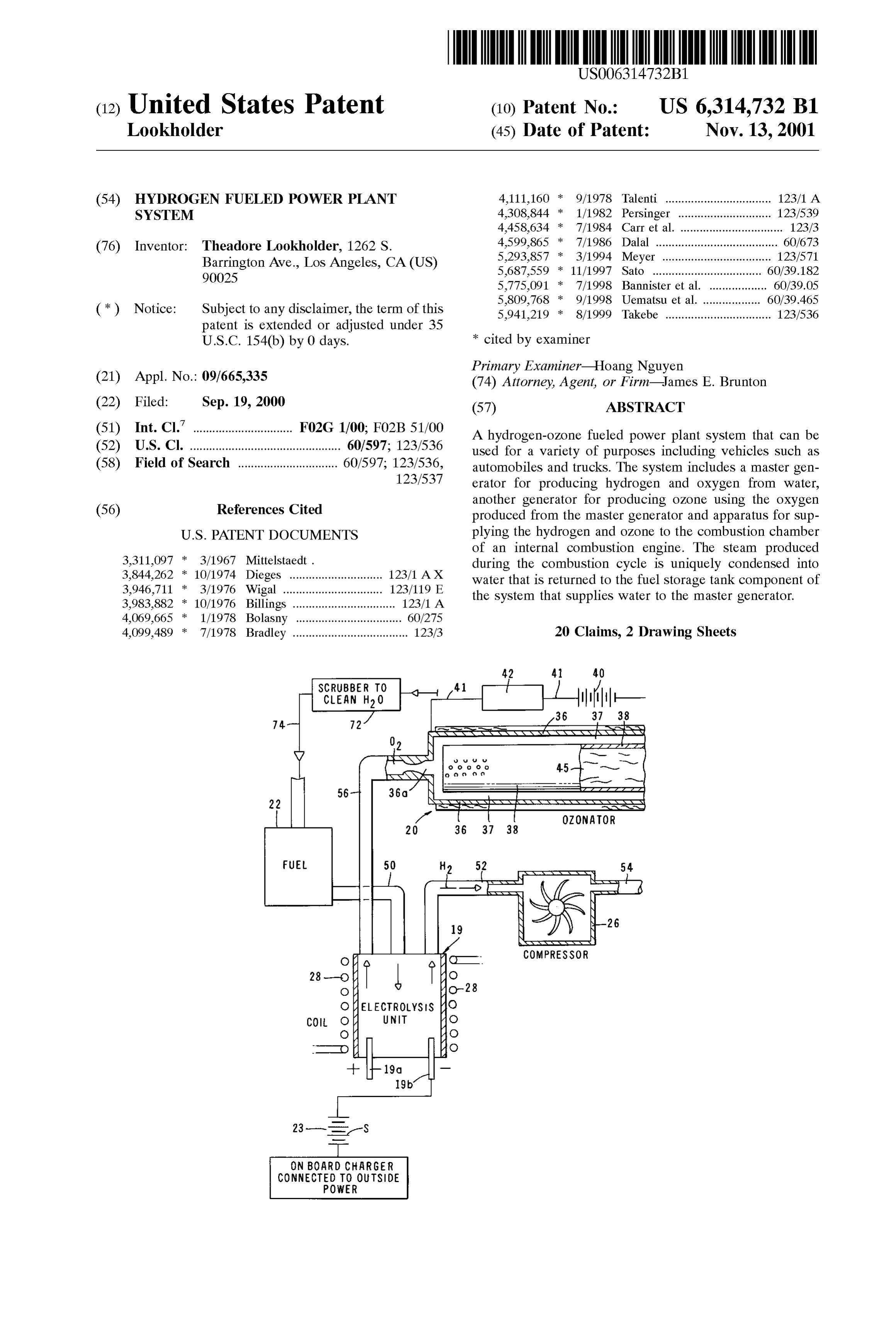
(51) Int. Cl. ... . . F02G 1/00; F2B 51/00 A hydrogen-OZone fueled power plant System that can be (52) U.S. C. ---- ------------- --- --- ------- --- --- ------- --- - 60/597; 123/536 used for Variety of purposes including vehicles Such S
(58) Field of Search ............................... 60/597; 123/536, automobiles and trucks. The System includes a master gen 123/537 erator for producing hydrogen and oxygen from water, another generator for producing OZone using the oxygen (56) References Cited produced from the master generator and apparatus for Sup
of an internal combustion engine. The Steam produced 3,311,097 * 3/1967 Mittelstaedt. during the combustion cycle is uniquely condensed into 3. : ly: RS -- --- ------- --- --- ----------- ?f water that is returned to the fuel Storage tank component of
3,983,882 * 10/1976 Billings .. ... 123/1 A the System that Supplies water to the master generator. 4,069,665 1/1978 Bolasny ................................. 60/275 4,099,489 * 7/1978 Bradley .................................... 123/3 20 Claims, 2 Drawing Sheets
ZZZZ Zee
N Rassists
COMPRESSOR
ON BOARD CHARGER
CONNECTED TO OUTSIDE
POWER
Page 2
CLEAN HO |-
V -QT N
22 NSs. YY N. a aaaaaaaaaaaaaaS
F. G. A ls OZ . . COMPRESSOR
OELECTROLYSIS 19
23-E-S SN
s 61 c f ; ON BOARD CHARGER ELECTRONIC CONTROL UNIT
CONNECTED TO OUTSDE
POWER CONTROLS ALL FUNCTIONS
Page 3
Drawing sheet — no readable text.
Page 4
HYDROGEN FUELED POWER PLANT intermediate pressure turbine, thus creating more rotating SYSTEM shaft power. The Steam from the intermediate preSSure turbine is fed into a heat recovery Steam generator that cools
BACKGROUND OF THE INVENTION the Steam and heats water Streams to form cooling Steam for at least one of the turbines and combustors. The now cooled 1. Field of the Invention
Steam exits the Steam generator and passes through a low
The present invention relates generally to internal com preSSure turbine thereby generating more rotating shaft bustion engines. More particularly, the invention concerns power and is condensed into water Streams for heating into an internal combustion engine that is fueled by a mixture of cooling Steam in the Steam generator. hydrogen and OZone. U.S. Pat. No. 3,844,262 issued to Dieges discloses an 2. Discussion of the Prior Art open-cycle, internal combustion engine that uses in combi The great majority of internal combustion engines in nation oxygen and hydrogen burned as fuel in the combus present use are fueled by hydrocarbon fossil fuel that tion chamber of the engine. In the Dieges apparatus, the exhausts hydrocarbons, nitric oxides, carbon dioxide and oxygen and hydrogen is mixed with a Surplus gas and carbon monoxide. As a result of the high levels of pollution 15 comprises a Substantially closed System which circulates the in the atmosphere from current engines, the U.S. Govern Surplus gas through the System for reuse and expels only the ment has Set new emission Standards for automotive vehicle water of combustion to the atmosphere. engines, which require a considerable reduction in pollutants U.S. Pat. No. 4,599,865 Dalal relates to a method and over the next Several years. apparatus for a combustion of hydrogen to produce heat for Because of the pollution problems caused by conventional generating Steam for power generation. The Dalal apparatus internal combustion engines, electric battery driven and includes two electrolytic cells which generate hydrogen and various other engines have been Suggested for powering oxygen by electrolysis of acidulated water. automotive vehicles. However, the gasoline powered inter U.S. Pat. No. 5,782,081 issued to Pak et al discloses a nal combustion engine has retained widespread usage in 25 hydrogen-oxygen burning turbine plant which comprises a automobiles and trucks because of its ability to operate over closed loop turbine cycle including a compressor, a a wide range of power demands and Speeds and its ability to hydrogen/oxygen combustor and a turbine. be relatively inexpensively manufactured. U.S. Pat. No. 4,308,844 issued to Persinger discloses a The present invention contemplates using the basic con method and apparatus for improving the efficiency of an ventional internal combustion engine design because of its internal combustion engine by producing OZone gas and reliability and other proven qualities. However, rather then positively charged air particles in a Supply of air to an using fossil fuels, the power plant System of the present engine. The apparatus comprises an OZone generator cell invention is adapted to use hydrogen as a fuel both for the Suitably position with respect to the engine So that an air purpose of reducing harmful exhaust emissions and also for Supply to the engine passes between adjacent tubes of the providing a more efficient engine. The hydrogen fueled 35 OZOne generator.
power plant System of the invention as disclosed herein can Unlike the prior art devices of the character discussed in be used in connection with vehicles, but also can be used for the preceding paragraphs, the apparatus of the present inven power plant purposes other than powering a vehicle. tion uniquely captures the Steam generated during the com In contrast to hydrocarbon fueled internal combustion bustion of the hydrogen and OZone fuel, condenses the Steam engines, the hydrogen-OZone fueled power plant System of 40 to produce water which is scrubbed and returned to the fuel the present invention will emit virtually no pollutants with tank in a closed System.
the virtual elimination of carbon monoxide and hydrocar SUMMARY OF THE INVENTION bons. Further, due to the unique design of the power plant
System of the invention, the Steam produced during the It is an object of the present invention to provide a novel, combustion cycle is condensed and then recycled through a 45 hydrogen-OZone fueled power plant System that can be used closed System for reuse in producing the hydrogen-OZone for a variety of purposes including vehicles Such as auto fuel used to power the internal combustion engine compo mobiles and truckS.
nent of the System. More particularly, it is an object of the invention to The use of hydrogen and oxygen as a fuel for internal provide a power plant System of the aforementioned char combustion engines is discussed in U.S. Pat. No. 3,311,097 50 acter that includes a master generator for producing hydro issued to Mittelstaedt. As disclosed in the Mittelstaedt gen and oxygen from water, another generator for producing patent, liberated hydrogen and oxygen gases are introduced oZone using the oxygen produced from the master generator into the combustion Zone of the engine as a fuel where the and means for Supplying the hydrogen and OZone to the gases are introduced into the intake line of the engine to combustion chamber of an internal combustion engine. combine with the intake air or fuel or mixture thereof to 55 Another object of the invention is to provide a power plant enrich and improve the charge to promote combustion to System as described in the preceding paragraphs in which produce leSS toxic combustion products, to increase power, the Steam produced during the combustion cycle is con to increase the efficiency of the engine, and/or to economize densed into water that is returned to the fuel Storage tank on fuel. component of the System that Supplies water to the master U.S. Pat. No. 5,775,091 issued to Bannister etal discloses 60 generator.
a power plant that combusts hydrogen with oxygen in a high Another object of the invention is to provide a power plant preSSure combustor to produce Steam. The produced Steam System of the character described that is highly efficient in is mixed with cooling Steam before being Sent to a high operation, is of a simple construction and is virtually pol preSSure expander which expands the Steam and generates lution free.
rotating shaft power. The expanded Steam is mixed with 65 Another object of the invention is to provide a hydrogen Steam from the combustion of the hydrogen and oxygen in fueled power plant System that is both economical and an intermediate pressure combustor and is expanded in an reliable in operation.
Page 5
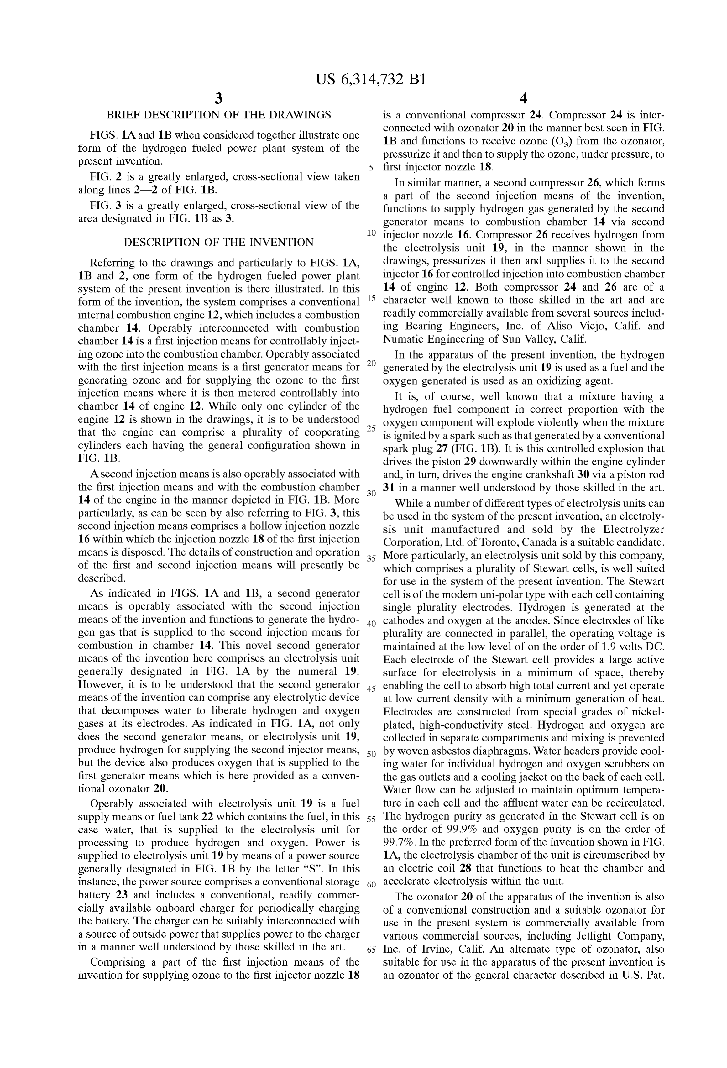
BRIEF DESCRIPTION OF THE DRAWINGS is a conventional compressor 24. Compressor 24 is inter connected with ozonator 20 in the manner best seen in FIG.
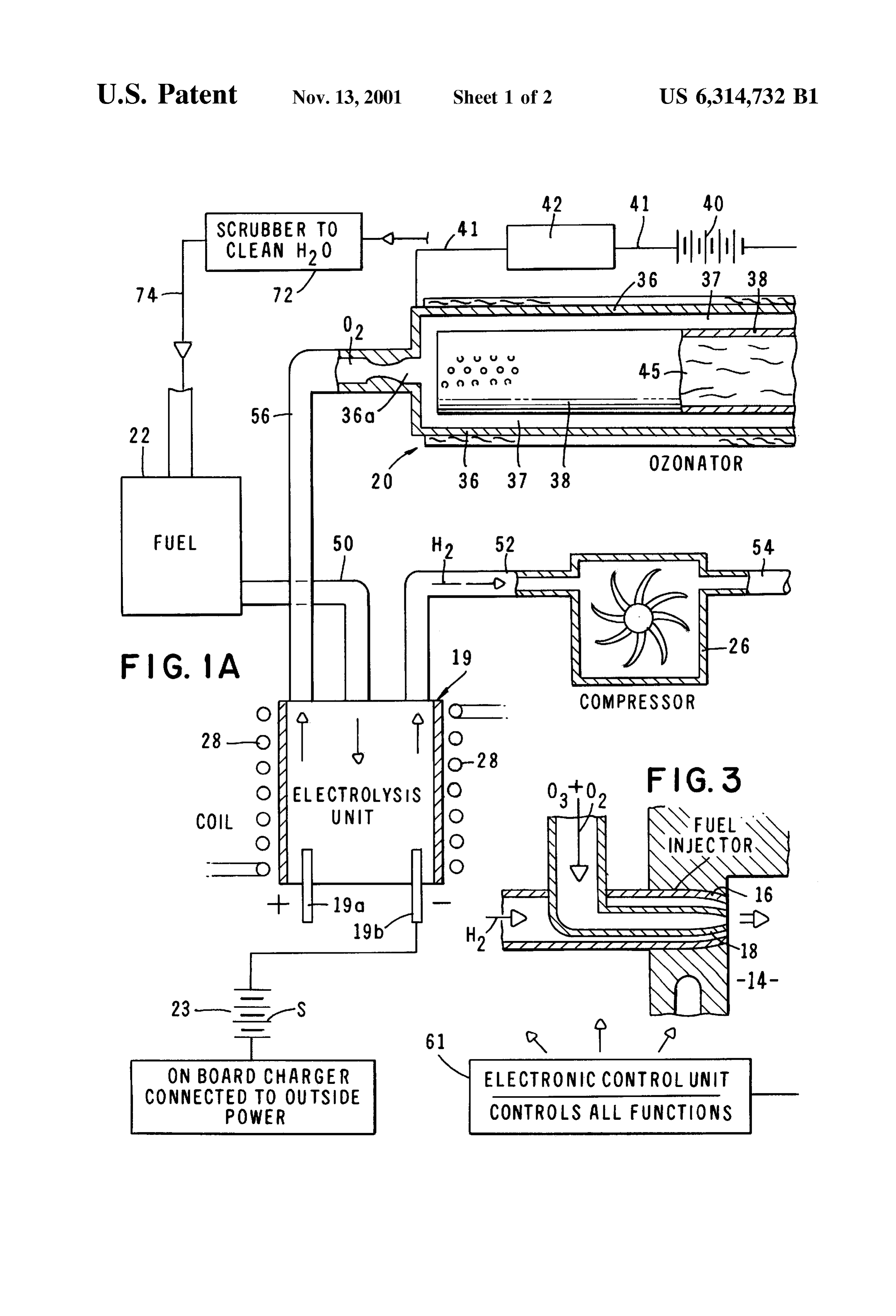
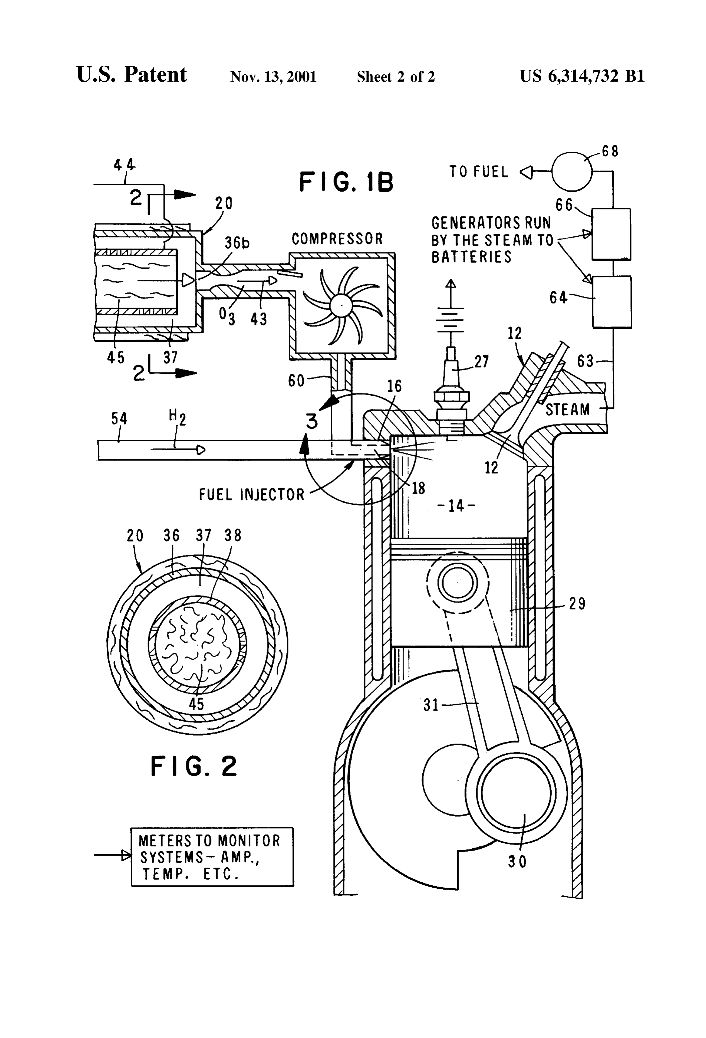
FIGS. 1A and 1B when considered together illustrate one 1B and functions to receive ozone (O) from the ozonator, form of the hydrogen fueled power plant System of the preSSurize it and then to Supply the OZone, under preSSure, to present invention. first injector nozzle 18.
FIG. 2 is a greatly enlarged, cross-sectional view taken In Similar manner, a Second compressor 26, which forms along lines 2-2 of FIG. 1B. a part of the Second injection means of the invention, FIG. 3 is a greatly enlarged, cross-sectional view of the functions to Supply hydrogen gas generated by the Second area designated in FIG. 1B as 3. generator means to combustion chamber 14 via Second
DESCRIPTION OF THE INVENTION
injector nozzle 16. Compressor 26 receives hydrogen from the electrolysis unit 19, in the manner shown in the
Referring to the drawings and particularly to FIGS. 1A, drawings, pressurizes it then and Supplies it to the Second 1B and 2, one form of the hydrogen fueled power plant injector 16 for controlled injection into combustion chamber System of the present invention is there illustrated. In this 15 14 of engine 12. Both compressor 24 and 26 are of a form of the invention, the System comprises a conventional character well known to those skilled in the art and are internal combustion engine 12, which includes a combustion readily commercially available from Several Sources includ chamber 14. Operably interconnected with combustion ing Bearing Engineers, Inc. of Aliso Viejo, Calif. and chamber 14 is a first injection means for controllably inject Numatic Engineering of Sun Valley, Calif. ing OZone into the combustion chamber. Operably associated In the apparatus of the present invention, the hydrogen with the first injection means is a first generator means for generated by the electrolysis unit 19 is used as a fuel and the generating OZone and for Supplying the OZone to the first OXygen generated is used as an oxidizing agent. injection means where it is then metered controllably into It is, of course, well known that a mixture having a chamber 14 of engine 12. While only one cylinder of the hydrogen fuel component in correct proportion with the engine 12 is shown in the drawings, it is to be understood 25 oxygen component will explode Violently when the mixture that the engine can comprise a plurality of cooperating is ignited by a Spark Such as that generated by a conventional cylinders each having the general configuration shown in spark plug 27 (FIG. 1B). It is this controlled explosion that FIG. 1B. drives the piston 29 downwardly within the engine cylinder A Second injection means is also operably associated with and, in turn, drives the engine crankshaft 30 via a piston rod the first injection means and with the combustion chamber 31 in a manner well understood by those skilled in the art. 14 of the engine in the manner depicted in FIG. 1B. More While a number of different types of electrolysis units can particularly, as can be seen by also referring to FIG. 3, this be used in the System of the present invention, an electroly Second injection means comprises a hollow injection nozzle sis unit manufactured and sold by the Electrolyzer 16 within which the injection nozzle 18 of the first injection Corporation, Ltd. of Toronto, Canada is a Suitable candidate. means is disposed. The details of construction and operation 35 More particularly, an electrolysis unit Sold by this company, of the first and Second injection means will presently be which comprises a plurality of Stewart cells, is well Suited described. for use in the system of the present invention. The Stewart As indicated in FIGS. 1A and 1B, a second generator cell is of the modem uni-polar type with each cell containing means is operably associated with the Second injection Single plurality electrodes. Hydrogen is generated at the means of the invention and functions to generate the hydro 40 cathodes and oxygen at the anodes. Since electrodes of like gen gas that is Supplied to the Second injection means for plurality are connected in parallel, the operating Voltage is combustion in chamber 14. This novel Second generator maintained at the low level of on the order of 1.9 volts DC. means of the invention here comprises an electrolysis unit Each electrode of the Stewart cell provides a large active generally designated in FIG. 1A by the numeral 19. Surface for electrolysis in a minimum of Space, thereby However, it is to be understood that the Second generator 45 enabling the cell to absorb high total current and yet operate means of the invention can comprise any electrolytic device at low current density with a minimum generation of heat. that decomposes water to liberate hydrogen and oxygen Electrodes are constructed from Special grades of nickel gases at its electrodes. AS indicated in FIG. 1A, not only plated, high-conductivity Steel. Hydrogen and oxygen are does the Second generator means, or electrolysis unit 19, collected in Separate compartments and mixing is prevented produce hydrogen for Supplying the Second injector means, 50 by woven asbestos diaphragms. Water headers provide cool but the device also produces oxygen that is Supplied to the ing water for individual hydrogen and oxygen Scrubbers on first generator means which is here provided as a conven the gas outlets and a cooling jacket on the back of each cell. tional ozonator 20. Water flow can be adjusted to maintain optimum tempera Operably associated with electrolysis unit 19 is a fuel ture in each cell and the affluent water can be recirculated. Supply means or fuel tank 22 which contains the fuel, in this 55 The hydrogen purity as generated in the Stewart cell is on case water, that is Supplied to the electrolysis unit for the order of 99.9% and oxygen purity is on the order of processing to produce hydrogen and oxygen. Power is 99.7%. In the preferred form of the invention shown in FIG. Supplied to electrolysis unit 19 by means of a power Source 1A, the electrolysis chamber of the unit is circumscribed by generally designated in FIG. 1B by the letter “S”. In this an electric coil 28 that functions to heat the chamber and instance, the power Source comprises a conventional Storage 60 accelerate electrolysis within the unit. battery 23 and includes a conventional, readily commer The ozonator 20 of the apparatus of the invention is also cially available onboard charger for periodically charging of a conventional construction and a Suitable oZonator for the battery. The charger can be Suitably interconnected with use in the present System is commercially available from a Source of outside power that Supplies power to the charger various commercial Sources, including Jetlight Company, in a manner well understood by those skilled in the art. 65 Inc. of Irvine, Calif. An alternate type of OZonator, also Comprising a part of the first injection means of the Suitable for use in the apparatus of the present invention is invention for Supplying OZone to the first injector nozzle 18 an OZonator of the general character described in U.S. Pat.
Page 6
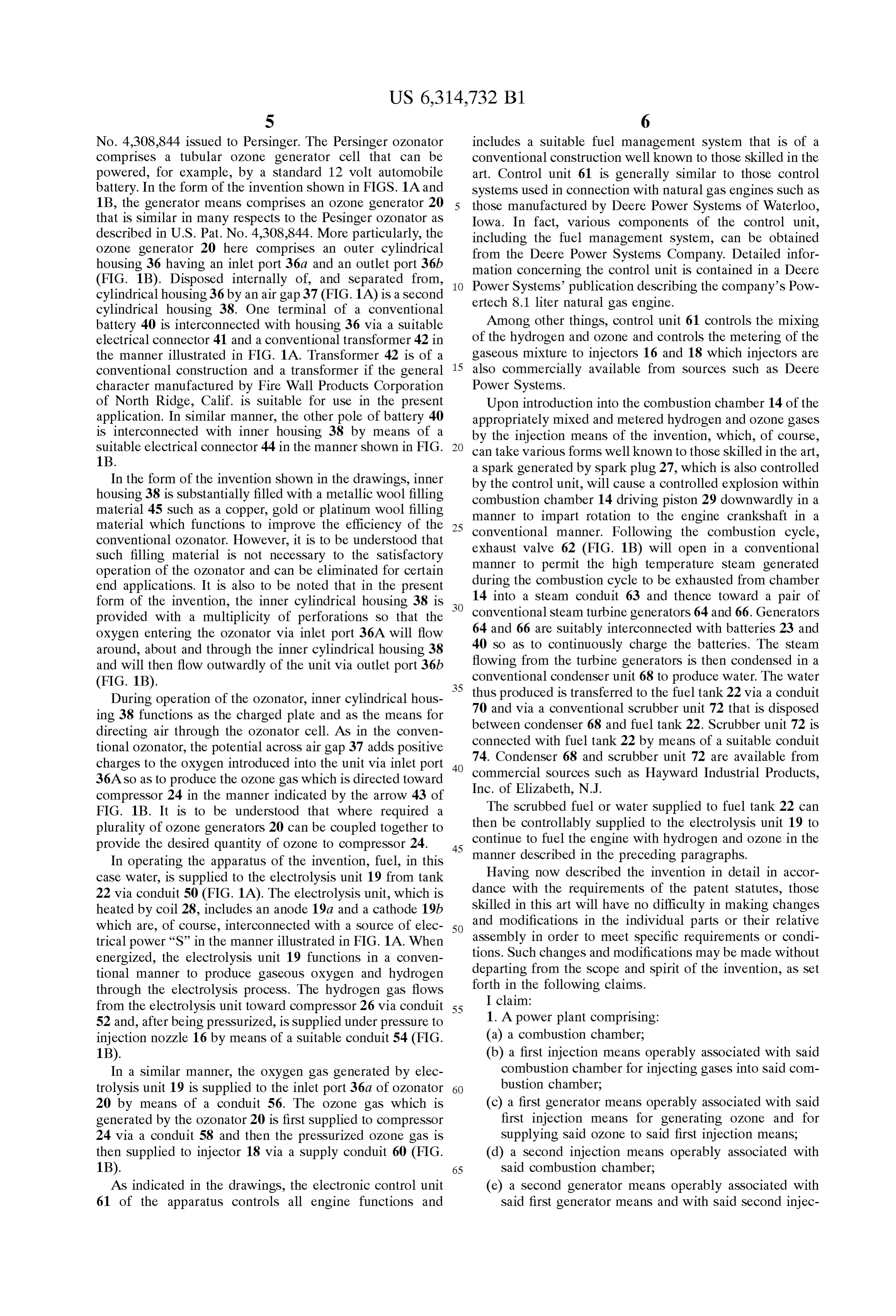
S 6
No. 4,308,844 issued to Persinger. The Persinger ozonator includes a Suitable fuel management System that is of a comprises a tubular OZone generator cell that can be conventional construction well known to those skilled in the powered, for example, by a Standard 12 volt automobile art. Control unit 61 is generally similar to those control battery. In the form of the invention shown in FIGS. 1A and Systems used in connection with natural gas engines Such as 1B, the generator means comprises an OZone generator 20 those manufactured by Deere Power Systems of Waterloo, that is similar in many respects to the Pesinger OZonator as Iowa. In fact, Various components of the control unit, described in U.S. Pat. No. 4,308,844. More particularly, the including the fuel management System, can be obtained oZone generator 20 here comprises an outer cylindrical from the Deere Power Systems Company. Detailed infor housing 36 having an inlet port 36a and an outlet port 36b
(FIG. 1B). Disposed internally of, and separated from, mation concerning the control unit is contained in a Deere Power Systems publication describing the company's Pow cylindrical housing 36 by an air gap 37 (FIG. 1A) is a second ertech 8.1 liter natural gas engine. cylindrical housing 38. One terminal of a conventional battery 40 is interconnected with housing 36 via a suitable Among other things, control unit 61 controls the mixing electrical connector 41 and a conventional transformer 42 in of the hydrogen and OZone and controls the metering of the the manner illustrated in FIG. 1A. Transformer 42 is of a gaseous mixture to injectors 16 and 18 which injectors are conventional construction and a transformer if the general 15 also commercially available from Sources Such as Deere character manufactured by Fire Wall Products Corporation Power Systems.
of North Ridge, Calif. is suitable for use in the present Upon introduction into the combustion chamber 14 of the application. In similar manner, the other pole of battery 40 appropriately mixed and metered hydrogen and OZone gases is interconnected with inner housing 38 by means of a by the injection means of the invention, which, of course, Suitable electrical connector 44 in the manner shown in FIG. can take various forms well known to those skilled in the art, 1B. a Spark generated by Spark plug 27, which is also controlled In the form of the invention shown in the drawings, inner by the control unit, will cause a controlled explosion within housing 38 is substantially filled with a metallic wool filling combustion chamber 14 driving piston 29 downwardly in a material 45 Such as a copper, gold or platinum wool filling manner to impart rotation to the engine crankshaft in a material which functions to improve the efficiency of the 25 conventional manner. Following the combustion cycle, conventional OZonator. However, it is to be understood that exhaust valve 62 (FIG. 1B) will open in a conventional Such filling material is not necessary to the Satisfactory manner to permit the high temperature Steam generated operation of the OZonator and can be eliminated for certain during the combustion cycle to be exhausted from chamber end applications. It is also to be noted that in the present form of the invention, the inner cylindrical housing 38 is 14 into a steam conduit 63 and thence toward a pair of provided with a multiplicity of perforations so that the conventional Steam turbine generators 64 and 66. Generators oxygen entering the OZonator via inlet port 36A will flow 64 and 66 are suitably interconnected with batteries 23 and around, about and through the inner cylindrical housing 38 40 So as to continuously charge the batteries. The Steam and will then flow outwardly of the unit via outlet port 36b flowing from the turbine generators is then condensed in a (FIG. 1B). 35 conventional condenser unit 68 to produce water. The water
During operation of the OZonator, inner cylindrical hous thus produced is transferred to the fuel tank 22 via a conduit ing 38 functions as the charged plate and as the means for between70 and via a conventional scrubber unit 72 that is disposed condenser 68 and fuel tank 22. Scrubber unit 72 is directing air through the OZonator cell. AS in the conven connected tional OZonator, the potential acroSS air gap 37 adds positive 74. Condenser with fuel tank 22 by means of a Suitable conduit 68 and Scrubber unit 72 are available from charges to the oxygen introduced into the unit via inlet port 40 36ASO as to produce the OZone gas which is directed toward Inc. of Elizabeth, N.J.Such as Hayward Industrial Products, commercial Sources compressor 24 in the manner indicated by the arrow 43 of
FIG. 1B. It is to be understood that where required a The scrubbed fuel or water Supplied to fuel tank 22 can plurality of OZone generators 20 can be coupled together to then be controllably supplied to the electrolysis unit 19 to provide the desired quantity of OZone to compressor 24. 45 continue to fuel the engine with hydrogen and OZone in the In operating the apparatus of the invention, fuel, in this manner described in the preceding paragraphs. case water, is Supplied to the electrolysis unit 19 from tank Having now described the invention in detail in accor 22 via conduit 50 (FIG. 1A). The electrolysis unit, which is dance with the requirements of the patent Statutes, those heated by coil 28, includes an anode 19a and a cathode 19b skilled in this art will have no difficulty in making changes which are, of course, interconnected with a Source of elec 50 and modifications in the individual parts or their relative trical power “S” in the manner illustrated in FIG. 1A. When assembly in order to meet Specific requirements or condi energized, the electrolysis unit 19 functions in a conven tions. Such changes and modifications may be made without tional manner to produce gaseous oxygen and hydrogen departing from the Scope and Spirit of the invention, as Set through the electrolysis process. The hydrogen gas flows forth in the following claims.
from the electrolysis unit toward compressor 26 via conduit 55 I1.claim:
A power plant comprising:
52 and, after being pressurized, is Supplied under pressure to injection nozzle 16 by means of a suitable conduit 54 (FIG. (a) a combustion chamber;
1B). (b) a first injection means operably associated with said In a Similar manner, the oxygen gas generated by elec combustion chamber for injecting gases into Said com trolysis unit 19 is supplied to the inlet port 36a of ozonator 60 bustion chamber;
20 by means of a conduit 56. The ozone gas which is (c) a first generator means operably associated with said generated by the OZonator 20 is first Supplied to compressor first injection means for generating OZone and for 24 via a conduit 58 and then the pressurized OZone gas is Supplying Said OZone to Said first injection means, then supplied to injector 18 via a supply conduit 60 (FIG. (d) a Second injection means operably associated with 1B). 65 Said combustion chamber; AS indicated in the drawings, the electronic control unit (e) a second generator means operably associated with 61 of the apparatus controls all engine functions and Said first generator means and with Said Second injec
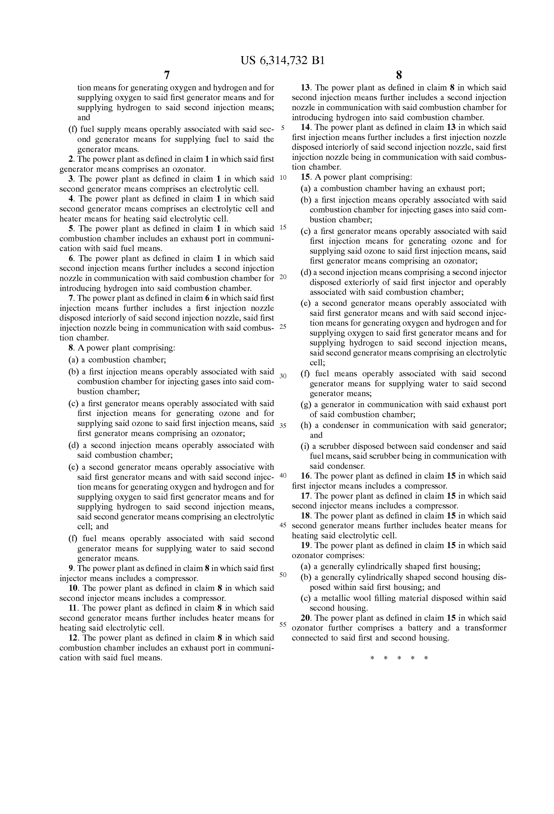
Page 7
tion means for generating oxygen and hydrogen and for 13. The power plant as defined in claim 8 in which said Supplying oxygen to Said first generator means and for Second injection means further includes a Second injection Supplying hydrogen to Said Second injection means, nozzle in communication with Said combustion chamber for and introducing hydrogen into Said combustion chamber. (f) fuel Supply means operably associated with said Sec 14. The power plant as defined in claim 13 in which said ond generator means for Supplying fuel to Said the first injection means further includes a first injection nozzle generator means. disposed interiorly of Said Second injection nozzle, Said first 2. The power plant as defined in claim 1 in which said first injection nozzle being in communication with Said combus generator means comprises an OZonator. tion chamber.
3. The power plant as defined in claim 1 in which said 15. A power plant comprising:
Second generator means comprises an electrolytic cell. (a) a combustion chamber having an exhaust port; 4. The power plant as defined in claim 1 in which said (b) a first injection means operably associated with said Second generator means comprises an electrolytic cell and combustion chamber for injecting gases into Said com heater means for heating Said electrolytic cell. bustion chamber;
5. The power plant as defined in claim 1 in which said 15 (c) a first generator means operably associated with said combustion chamber includes an exhaust port in communi first injection means for generating OZone and for cation with Said fuel means. Supplying Said OZone to Said first injection means, Said 6. The power plant as defined in claim 1 in which said first generator means comprising an OZonator; Second injection means further includes a Second injection (d) a second injection means comprising a second injector nozzle in communication with Said combustion chamber for disposed exteriorly of Said first injector and operably introducing hydrogen into Said combustion chamber. asSociated with Said combustion chamber; 7. The power plant as defined in claim 6 in which said first (e) a second generator means operably associated with injection means further includes a first injection nozzle Said first generator means and with Said Second injec disposed interiorly of Said Second injection nozzle, Said first tion means for generating oxygen and hydrogen and for injection nozzle being in communication with Said combus 25 Supplying oxygen to Said first generator means and for tion chamber.
8. A power plant comprising: Supplying hydrogen to Said Second injection means, Said Second generator means comprising an electrolytic (a) a combustion chamber; cell;
(b) a first injection means operably associated with said (f) fuel means operably associated with Said Second combustion chamber for injecting gases into Said com generator means for Supplying water to Said Second bustion chamber; generator means, (c) a first generator means operably associated with said (g) a generator in communication with said exhaust port first injection means for generating OZone and for of Said combustion chamber;
Supplying Said OZone to Said first injection means, Said 35 (h) a condenser in communication with Said generator; first generator means comprising an OZonator; and (d) a Second injection means operably associated with (i) a Scrubber disposed between said condenser and said Said combustion chamber; fuel means, Said Scrubber being in communication with (e) a second generator means operably associative with 40 Said condenser.
Said first generator means and with Said Second injec 16. The power plant as defined in claim 15 in which said tion means for generating oxygen and hydrogen and for first injector means includes a compressor. Supplying oxygen to Said first generator means and for 17. The power plant as defined in claim 15 in which said Supplying hydrogen to Said Second injection means, Second injector means includes a compressor. Said Second generator means comprising an electrolytic 18. The power plant as defined in claim 15 in which said cell; and 45 Second generator means further includes heater means for
(f) fuel means operably associated with said Second heating Said electrolytic cell.
generator means for Supplying water to Said Second 19. The power plant as defined in claim 15 in which said generator means. oZonator comprises:
9. The power plant as defined in claim 8 in which said first 50 (a) a generally cylindrically shaped first housing; injector means includes a compressor. (b) a generally cylindrically shaped second housing dis 10. The power plant as defined in claim 8 in which said posed within Said first housing, and Second injector means includes a compressor. (c) a metallic wool filling material disposed within Said 11. The power plant as defined in claim 8 in which said Second housing.
Second generator means further includes heater means for 55 20. The power plant as defined in claim 15 in which said heating Said electrolytic cell. oZonator further comprises a battery and a transformer 12. The power plant as defined in claim 8 in which said connected to Said first and Second housing. combustion chamber includes an exhaust port in communi cation with Said fuel means. k k k k k
Provenance
- Collection
- Patents citing this work
- Current assignee
- JUSTH LORI, LOOKHOLDER SCOTT
- Pages
- 7
- Method
- pdftotext (the PDF's own text layer) + pdftoppm 300dpi page scans
- Patent office record
- patents.google.com →
- Source
- Google Patents citing-documents table
- Inventors
- Theadore Lookholder
- Published
- 2001-11-13
- Transcribed from
- patentimages.storage.googleapis.com →