patent · US4069665
Gas ionizing apparatus for improving the operation of an internal combustion engine
24 January 1978
Page 1 — bibliographic record
United States Patent (19) 11) 4,069,665 Bolasny 45) Jan. 24, 1978
54 GASIONIZINGAPPARATUS FOR
IMPROVING THE OPERATION OF AN FOREIGN PATENT DOCUMENTS INTERNAL COMBUSTION ENGINE 959,669 10/1949 France ......... e o we v w w & v a t + · P D 123/119 E
75 Inventor: Robert E. Bolasny, Boulder, Colo. Primary Examiner-Douglas Hart 73 Assignee: Scientific Enterprises, Inc y Attorney, Agent, or Firm-Ancel W. Lewis, Jr. Broomfield, Colo. 57 ABSTRACT 21 Appl. No.: 634,638 A method and apparatus for producing ions wherein an 22 Filed: Nov. 24, 1975 ion generator produces periodic pulses of electric en
ergy of a single polarity for some applications and alter nating positive and negative polarities for other applica
Related U.S. Application Data tions. A plurality of the electric pulses are limited in 62 Division of Ser. No. 384,464, Aug. 1, 1973, Pat. No. amplitude by a substantially sinusoidal half-wave enve 3,943,407. lope and the positive and negative pulses are preferably 51) Int. Cl? .............................................. F02B 75/10 of different amplitudes. The ground electrode is ar 52 U.S. C. .................................. co/27s. 123/119 E.
ranged about and upstream and downstream of the ionizing electrode to provide a highly effective electric 58 Field of Search .............. 60/303, 275; 133/119 E, field substantially normal to the gas flow. A heater heats 317/262 AE; 204/164; 250/532,531, 537, 426 the gas to increase ionization, An ultrasonic sound wave generator pulses the gas with sound waves prior to, 56 References Cited during or after ionization of the gas to group the ions of
1,614,234 1/1927 Trairun ............................... 123/119 E
areas so as to reduce recombination of ions thereby making more ions available per volume and also in 1,872,065 8/1932 Duffendack ......................... 20/164 creasing the total energy of the ions produced. Multiple 1,873,746 8/1932 English ..... ... 23/19 E sound wave generators increase the energy of the base 2,005,249 6/1935 Tietig ..................................... 60/303 frequency or selected harmonics. An inlet passage to 2,060,842 11/1936 Yaglou ...... 317/262 AE the generator of a selected length increases the energy. 3,091,920 6/1963 Matvay .................................. 9/27 A discharge passage of a selected length reinforces E. 3: Gy. a O.S: and/or eliminates selected harmonics. A discharge noz 3,476,095 11/1969 Laubarede ..., 123/119 E zle with angularly inclined and outwardly enlarged 3,841,824 10/1974 Bethel .................................... 60s venturis cool the heated ionized gas. 3,846,637 11/1974 Gettinger ............................... 60/275 3,882,677 5/1975 Eknayan ................................ 60/303 7 Claims, 26 Drawing Figures
Page 2
Drawing sheet — no readable text.
Page 3
Drawing sheet — no readable text.
Page 4
Drawing sheet — no readable text.
Page 5
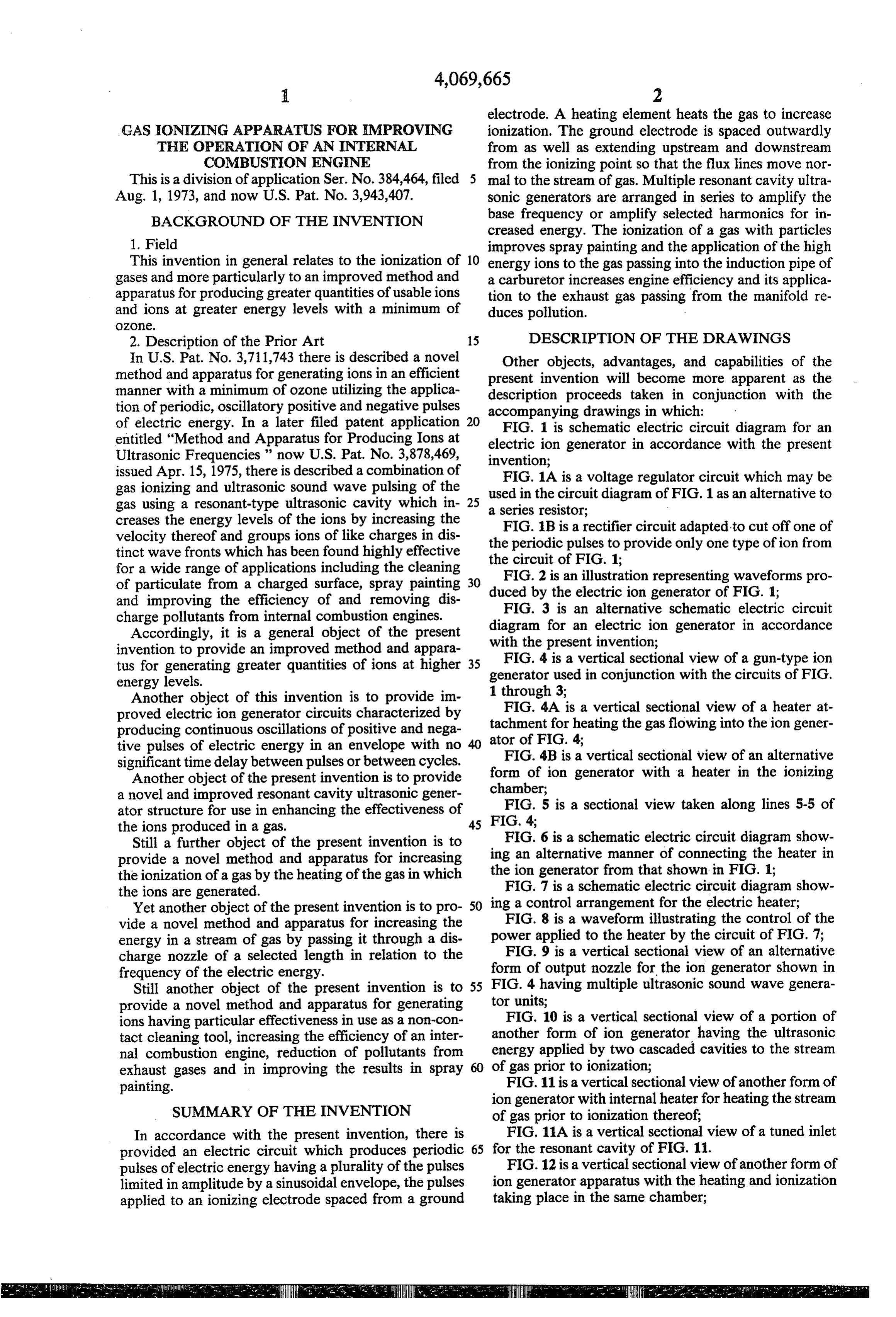
electrode. A heating element heats the gas to increase
GAS ONIZINGAPPARATUS FOR IMPROVING ionization. The ground electrode is spaced outwardly THE OPERATION OF AN INTERNAL from as well as extending upstream and downstream COMBUSTON ENGINE from the ionizing point so that the flux lines move nor This is a division of application Ser. No. 384,464, filed 5 mal to the stream of gas. Multiple resonant cavity ultra Aug. 1, 1973, and now U.S. Pat. No. 3,943,407. sonic generators are arranged in series to amplify the BACKGROUND OF THE INVENTION base frequency or amplify selected harmonics for in creased energy. The ionization of a gas with particles 1. Field improves spray painting and the application of the high This invention in general relates to the ionization of 10 energy ions to the gas passing into the induction pipe of gases and more particularly to an improved method and a carburetor increases engine efficiency and its applica apparatus for producing greater quantities of usable ions tion to the exhaust gas passing from the manifold re and ions at greater energy levels with a minimum of duces pollution.
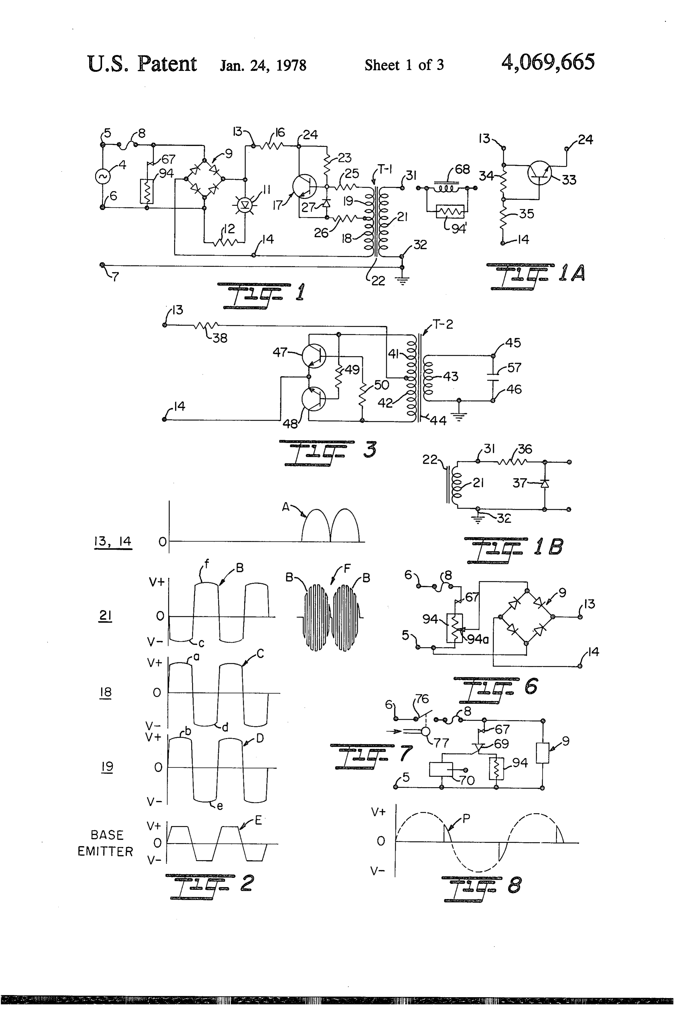
OZOc, 2. Description of the Prior Art 15 DESCRIPTION OF THE DRAWINGS In U.S. Pat. No. 3,711,743 there is described a novel Other objects, advantages, and capabilities of the method and apparatus for generating ions in an efficient present invention will become more apparent as the manner with a minimum of ozone utilizing the applica description proceeds taken in conjunction with the tion of periodic, oscillatory positive and negative pulses accompanying drawings in which: of electric energy. In a later filed patent application FIG. 1 is schematic electric circuit diagram for an entitled "Method and Apparatus for Producing Ions at electric
Ultrasonic Frequencies' now U.S. Pat. No. 3,878,469, invention;ion generator in accordance with the present issued Apr. 15, 1975, there is described a combination of FIG. 1A is a voltage regulator circuit which may be gas ionizing and ultrasonic sound wave pulsing of the used in the circuit diagram of FIG. 1 as an alternative to gas using a resonant-type ultrasonic cavity which in 25 a series resistor;
creases the energy levels of the ions by increasing the velocity thereof and groups ions of like charges in dis theFIG. B is a rectifier circuit adapted to cut off one of tinct wave fronts which has been found highly effective the circuit ofpulses periodic
FIG.
to provide only one type of ion from
for a wide range of applications including the cleaning FIG. 2 is an illustration representing waveforms pro of particulate from a charged surface, spray painting 30 duced by the electric ion generator of FIG. 1; and improving the efficiency of and removing dis FIG. 3 is an alternative schematic electric circuit charge pollutants from internal combustion engines.
Accordingly, it is a general object of the present diagram for an electric ion generator in accordance invention to provide an improved method and appara with the present invention;
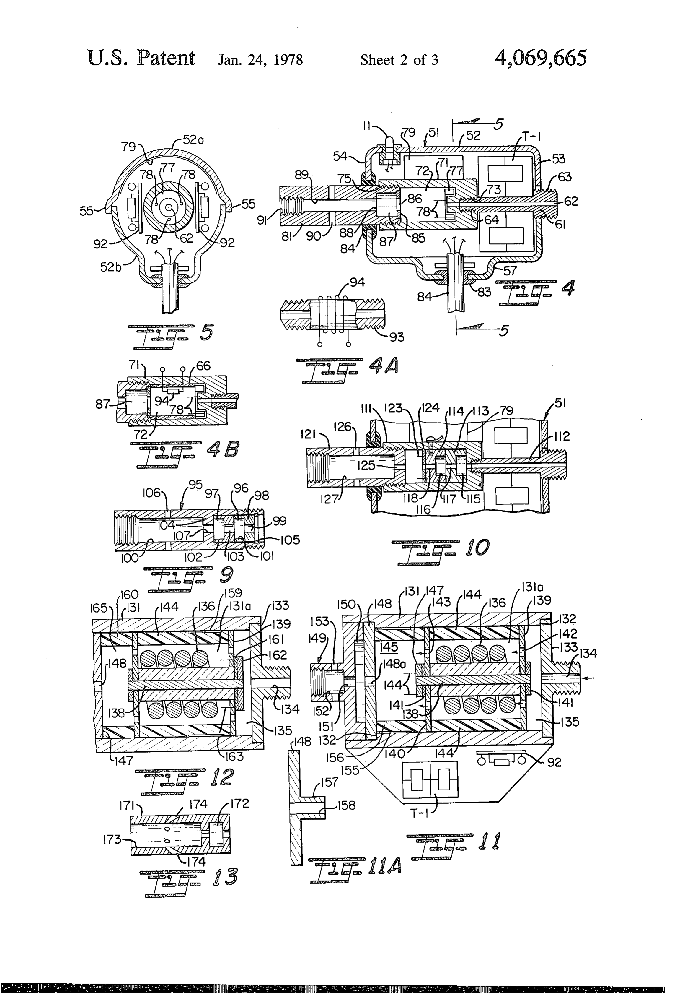
FIG. 4 is a vertical sectional view of a gun-type ion tus for generating greater quantities of ions at higher 35 generator used in conjunction with the circuits of FIG. energy levels. 1 through 3;
Another object of this invention is to provide im FIG. 4A is a vertical sectional view of a heater at proved electric ion generator circuits characterized by tachment for heating the gas flowing into the ion gener producing continuous oscillations of positive and nega tive pulses of electric energy in an envelope with no atorFIG. of FIG. 4;
significant time delay between pulses or between cycles. form of4Bionis generator a vertical sectional view of an alternative with a heater in the ionizing
Another object of the present invention is to provide chamber;
a novel and improved resonant cavity ultrasonic gener FIG. 5 is a sectional view taken along lines 5-5 of ator structure for use in enhancing the effectiveness of the ions produced in a gas. FIG. 4;
Still a further object of the present invention is to FIG. 6 is a schematic electric circuit diagram show provide a novel method and apparatus for increasing ing an alternative manner of connecting the heater in the ionization of a gas by the heating of the gas in which the ion generator from that shown in FIG. 1; the ions are generated. FIG. 7 is a schematic electric circuit diagram show Yet another object of the present invention is to pro 50 ing a control arrangement for the electric heater; vide a novel method and apparatus for increasing the FIG. 8 is a waveform illustrating the control of the energy in a stream of gas by passing it through a dis power applied to the heater by the circuit of FIG. 7; FIG. 9 is a vertical sectional view of an alternative charge nozzle of a selected length in relation to the form of output nozzle for the ion generator shown in frequency of the electric energy.
Still another object of the present invention is to 55 FIG. 4 having multiple ultrasonic sound wave genera provide a novel method and apparatus for generating tor units;
ions having particular effectiveness in use as a non-con FIG. 10 is a vertical sectional view of a portion of tact cleaning tool, increasing the efficiency of an inter another form of ion generator having the ultrasonic nal combustion engine, reduction of pollutants from energy applied by two cascaded cavities to the stream exhaust gases and in improving the results in spray of gas prior to ionization;
painting. FIG. 11 is a vertical sectional view of another form of ion generator with internal heater for heating the stream
SUMMARY OF THE INVENTION of gas prior to ionization thereof;
In accordance with the present invention, there is FIG. 11A is a vertical sectional view of a tuned inlet provided an electric circuit which produces periodic 65 for the resonant cavity of FIG. 11. pulses of electric energy having a plurality of the pulses FIG. 12 is a vertical sectional view of another form of limited in amplitude by a sinusoidal envelope, the pulses ion generator apparatus with the heating and ionization applied to an ionizing electrode spaced from a ground taking place in the same chamber;
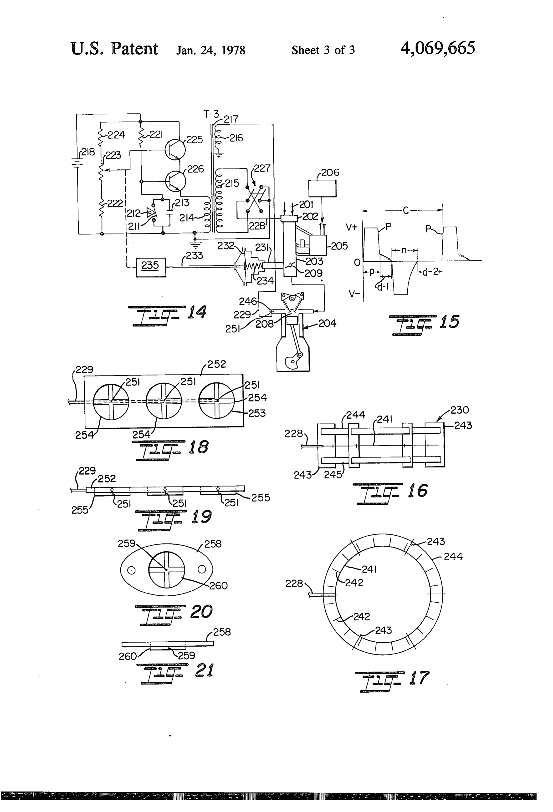
Page 6
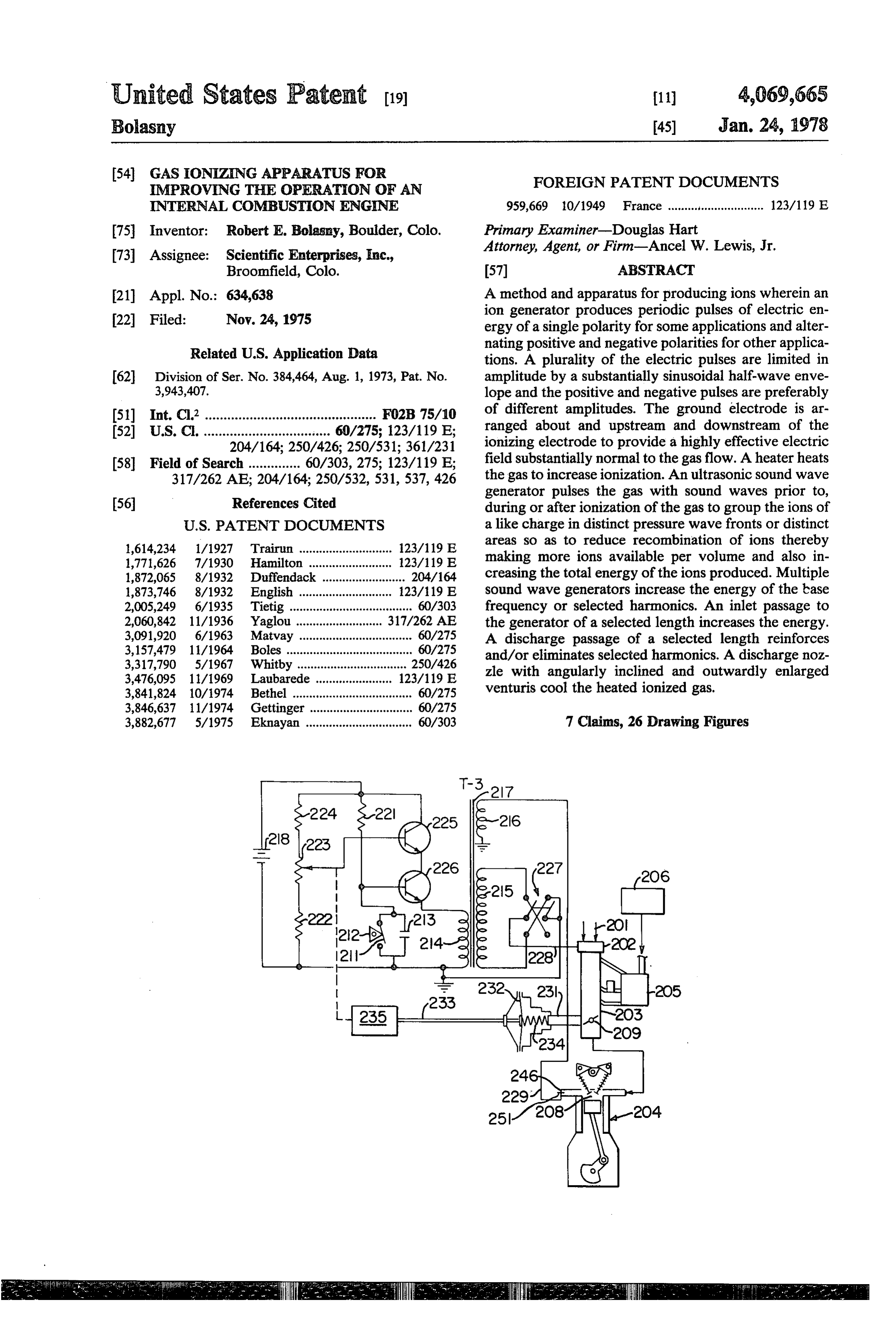
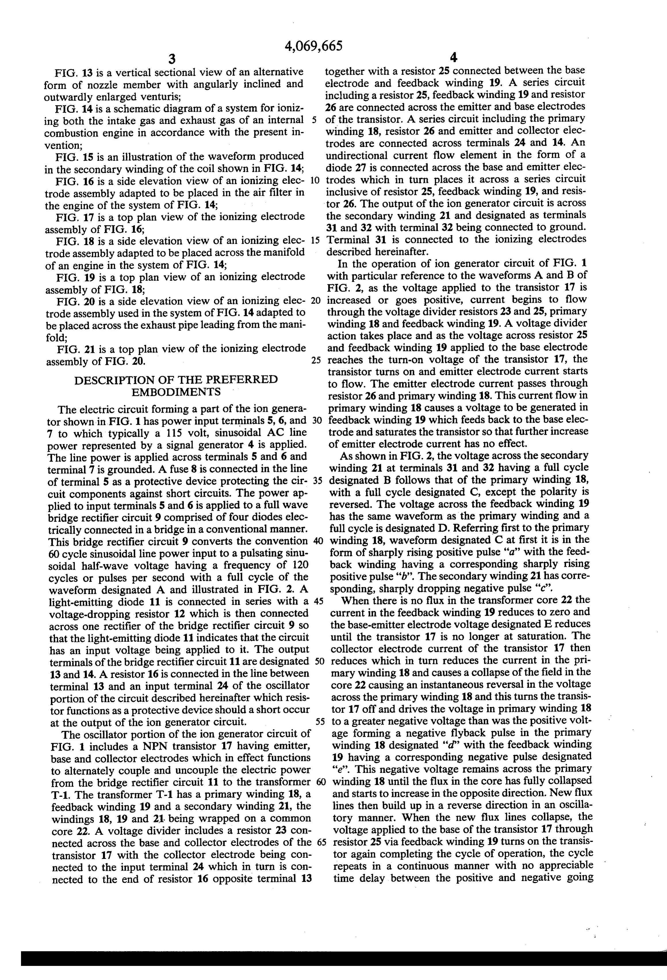
FIG. 13 is a vertical sectional view of an alternative together with a resistor 25 connected between the base form of nozzle member with angularly inclined and electrode and feedback winding 19. A series circuit outwardly enlarged venturis; including a resistor 25, feedback winding 19 and resistor FIG. 14 is a schematic diagram of a system for ioniz 26 are connected across the emitter and base electrodes ing both the intake gas and exhaust gas of an internal of the transistor. A series circuit including the primary combustion engine in accordance with the present in winding 18, resistor 26 and emitter and collector elec vention; trodes are connected across terminals 24 and 14. An FIG. 15 is an illustration of the waveform produced undirectional current flow element in the form of a in the secondary winding of the coil shown in FIG. 14; diode 27 is connected across the base and emitter elec FIG. 16 is a side elevation view of an ionizing elec 10 trodes which in turn places it across a series circuit trode assembly adapted to be placed in the air filter in inclusive of resistor 25, feedback winding 19, and resis the engine of the system of FIG. 14; tor 26. The output of the ion generator circuit is across FIG. 17 is a top plan view of the ionizing electrode the secondary winding 21 and designated as terminals assembly of FIG. 16; 31 and 32 with terminal 32 being connected to ground. FIG. 18 is a side elevation view of an ionizing elec 15 Terminal 31 is connected to the ionizing electrodes trode assembly adapted to be placed across the manifold described hereinafter.
of an engine in the system of FIG. 14; In the operation of ion generator circuit of FIG. 1 FIG. 19 is a top plan view of an ionizing electrode with particular reference to the waveforms A and B of assembly of FIG. 18; FIG. 2, as the voltage applied to the transistor 17 is FIG. 20 is a side elevation view of an ionizing elec 20 increased or goes positive, current begins to flow trode assembly used in the system of FIG. 14 adapted to through the voltage divider resistors 23 and 25, primary be placed across the exhaust pipe leading from the mani winding 18 and feedback winding 19. A voltage divider fold; action takes place and as the voltage across resistor 25 FIG. 21 is a top plan view of the ionizing electrode and feedback winding 19 applied to the base electrode assembly of FIG. 20. 25 reaches the turn-on voltage of the transistor 17, the transistor turns on and emitter electrode current starts
DESCRIPTION OF THE PREFERRED to flow. The emitter electrode current passes through EMBODIMENTS resistor 26 and primary winding 18. This current flow in The electric circuit forming a part of the ion genera primary winding 18 causes a voltage to be generated in tor shown in FIG. 1 has power input terminals 5, 6, and 30 feedback winding 19 which feeds back to the base elec 7 to which typically a 115 volt, sinusoidal AC line trode and saturates the transistor so that further increase power represented by a signal generator 4 is applied. of emitter electrode current has no effect. The line power is applied across terminals 5 and 6 and As shown in FIG. 2, the voltage across the secondary terminal 7 is grounded. A fuse 8 is connected in the line winding 21 at terminals 31 and 32 having a full cycle of terminal 5 as a protective device protecting the cir 35 designated B follows that of the primary winding 18, cuit components against short circuits. The power ap with a full cycle designated C, except the polarity is plied to input terminals 5 and 6 is applied to a full wave reversed. The voltage across the feedback winding 19 bridge rectifier circuit 9 comprised of four diodes elec has the same waveform as the primary winding and a trically connected in a bridge in a conventional manner. full cycle is designated D. Referring first to the primary This bridge rectifier circuit 9 converts the convention winding 18, waveform designated C at first it is in the 60 cycle sinusoidal line power input to a pulsating sinu form of sharply rising positive pulse "a" with the feed soidal half-wave voltage having a frequency of 120 back winding having a corresponding sharply rising cycles or pulses per second with a full cycle of the positive pulse "b'. The secondary winding 21 has corre waveform designated A and illustrated in FIG. 2. A sponding, sharply dropping negative pulse "c'. light-emitting diode 11 is connected in series with a 45 When there is no flux in the transformer core 22 the voltage-dropping resistor 12 which is then connected current in the feedback winding 19 reduces to zero and across one rectifier of the bridge rectifier circuit 9 so the base-emitter electrode voltage designated Ereduces that the light-emitting diode 11 indicates that the circuit until the transistor 17 is no longer at saturation. The has an input voltage being applied to it. The output collector electrode current of the transistor 17 then terminals of the bridge rectifier circuit 11 are designated 50 reduces which in turn reduces the current in the pri 13 and 14. A resistor 16 is connected in the line between mary winding 18 and causes a collapse of the field in the terminal 13 and an input terminal 24 of the oscillator core 22 causing an instantaneous reversal in the voltage portion of the circuit described hereinafter which resis across the primary winding 18 and this turns the transis tor functions as a protective device should a short occur tor 17 off and drives the voltage in primary winding 18 at the output of the ion generator circuit. 55 to a greater negative voltage than was the positive volt The oscillator portion of the ion generator circuit of age forming a negative flyback pulse in the primary FIG. 1 includes a NPN transistor 17 having emitter, winding 18 designated "d” with the feedback winding base and collector electrodes which in effect functions 19 having a corresponding negative pulse designated to alternately couple and uncouple the electric power 'e'. This negative voltage remains across the primary from the bridge rectifier circuit 11 to the transformer winding 18 until the flux in the core has fully collapsed T-1. The transformer T-1 has a primary winding 18, a and starts to increase in the opposite direction. New flux feedback winding 19 and a secondary winding 21, the lines then build up in a reverse direction in an oscilla windings 18, 19 and 21 being wrapped on a common tory manner. When the new flux lines collapse, the core 22. A voltage divider includes a resistor 23 con voltage applied to the base of the transistor 17 through nected across the base and collector electrodes of the 65 resistor 25 via feedback winding 19 turns on the transis transistor 17 with the collector electrode being con tor again completing the cycle of operation, the cycle nected to the input terminal 24 which in turn is con repeats in a continuous manner with no appreciable nected to the end of resistor 16 opposite terminal 13 time delay between the positive and negative going
Page 7
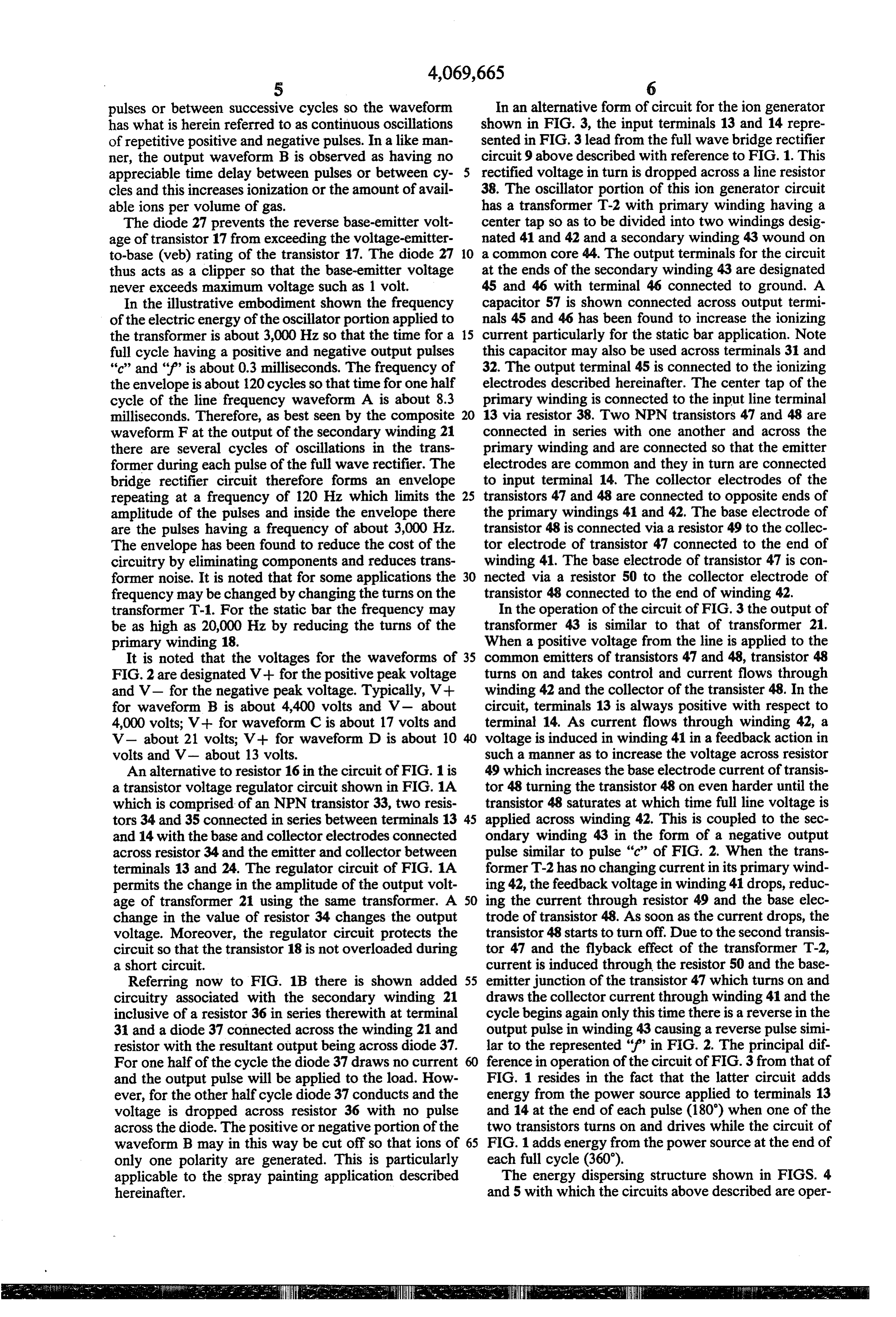
pulses or between successive cycles so the waveform In an alternative form of circuit for the ion generator has what is herein referred to as continuous oscillations shown in FIG. 3, the input terminals 13 and 14 repre of repetitive positive and negative pulses. In a like man sented in FIG. 3 lead from the full wave bridge rectifier ner, the output waveform B is observed as having no circuit 9 above described with reference to FIG.1. This appreciable time delay between pulses or between cy rectified voltage in turn is dropped across a line resistor cles and this increases ionization or the amount of avail 38. The oscillator portion of this ion generator circuit able ions per volume of gas. has a transformer T-2 with primary winding having a The diode 27 prevents the reverse base-emitter volt center tap so as to be divided into two windings desig age of transistor 17 from exceeding the voltage-emitter nated 41 and 42 and a secondary winding 43 wound on to-base (veb) rating of the transistor 17. The diode 27 10 a common core 44. The output terminals for the circuit thus acts as a clipper so that the base-emitter voltage at the ends of the secondary winding 43 are designated never exceeds maximum voltage such as 1 volt. 45 and 46 with terminal 46 connected to ground. A In the illustrative embodiment shown the frequency capacitor 57 is shown connected across output termi of the electric energy of the oscillator portion applied to nals 45 and 46 has been found to increase the ionizing the transformer is about 3,000 Hz so that the time for a 15 current particularly for the static bar application. Note full cycle having a positive and negative output pulses this capacitor may also be used across terminals 31 and 'c' and “f” is about 0.3 milliseconds. The frequency of 32. The output terminal 45 is connected to the ionizing the envelope is about 120 cycles so that time for one half electrodes described hereinafter. The center tap of the cycle of the line frequency waveform A is about 8.3 primary winding is connected to the input line terminal milliseconds. Therefore, as best seen by the composite 20 13 via resistor 38. Two NPN transistors 47 and 48 are waveform F at the output of the secondary winding 21 connected in series with one another and across the there are several cycles of oscillations in the trans primary winding and are connected so that the emitter former during each pulse of the full wave rectifier. The electrodes are common and they in turn are connected bridge rectifier circuit therefore forms an envelope to input terminal 14. The collector electrodes of the repeating at a frequency of 120 Hz which limits the 25 transistors 47 and 48 are connected to opposite ends of amplitude of the pulses and inside the envelope there the primary windings 41 and 42. The base electrode of are the pulses having a frequency of about 3,000 Hz. transistor 48 is connected via a resistor 49 to the collec The envelope has been found to reduce the cost of the tor electrode of transistor 47 connected to the end of circuitry by eliminating components and reduces trans winding 41. The base electrode of transistor 47 is con former noise. It is noted that for some applications the 30 nected via a resistor 50 to the collector electrode of frequency may be changed by changing the turns on the transistor 48 connected to the end of winding 42. transformer T-1. For the static bar the frequency may In the operation of the circuit of FIG. 3 the output of be as high as 20,000 Hz by reducing the turns of the transformer 43 is similar to that of transformer 21. primary winding 18. When a positive voltage from the line is applied to the It is noted that the voltages for the waveforms of 35 common emitters of transistors 47 and 48, transistor 48 FIG. 2 are designated V-- for the positive peak voltage turns on and takes control and current flows through and V- for the negative peak voltage. Typically, V-- winding 42 and the collector of the transister 48. In the for waveform B is about 4,400 volts and V- about circuit, terminals 13 is always positive with respect to 4,000 volts; V-- for waveform C is about 17 volts and terminal 14. As current flows through winding 42, a V- about 21 volts; V-- for waveform D is about 10 voltage is induced in winding 41 in a feedback action in volts and V- about 13 volts. such a manner as to increase the voltage across resistor An alternative to resistor 16 in the circuit of FIG. 1 is 49 which increases the base electrode current of transis a transistor voltage regulator circuit shown in FIG. 1A tor 48 turning the transistor 48 on even harder until the which is comprised of an NPN transistor 33, two resis transistor 48 saturates at which time full line voltage is tors 34 and 35 connected in series between terminals 13 45 applied across winding 42. This is coupled to the sec and 14 with the base and collector electrodes connected ondary winding 43 in the form of a negative output across resistor 34 and the emitter and collector between pulse similar to pulse “c” of FIG. 2. When the trans terminals 13 and 24. The regulator circuit of FIG. 1A former T-2 has no changing current in its primary wind permits the change in the amplitude of the output volt ing 42, the feedback voltage in winding 41 drops, reduc age of transformer 21 using the same transformer. A 50 ing the current through resistor 49 and the base elec change in the value of resistor 34 changes the output trode of transistor 48. As soon as the current drops, the voltage. Moreover, the regulator circuit protects the transistor 48 starts to turn off. Due to the second transis circuit so that the transistor 18 is not overloaded during tor 47 and the flyback effect of the transformer T-2, a short circuit. current is induced through the resistor 50 and the base Referring now to FIG. 1B there is shown added 55 emitter junction of the transistor 47 which turns on and circuitry associated with the secondary winding 21 draws the collector current through winding 41 and the inclusive of a resistor 36 in series therewith at terminal cycle begins again only this time there is a reverse in the 31 and a diode 37 connected across the winding 21 and output pulse in winding 43 causing a reverse pulse simi resistor with the resultant output being across diode 37. lar to the represented “f” in FIG. 2. The principal dif For one half of the cycle the diode 37 draws no current ference in operation of the circuit of FIG.3 from that of and the output pulse will be applied to the load. How FIG. 1 resides in the fact that the latter circuit adds ever, for the other half cycle diode 37 conducts and the energy from the power source applied to terminals 13 voltage is dropped across resistor 36 with no pulse and 14 at the end of each pulse (180') when one of the across the diode. The positive or negative portion of the two transistors turns on and drives while the circuit of waveform B may in this way be cut off so that ions of 65 FIG. 1 adds energy from the power source at the end of only one polarity are generated. This is particularly each full cycle (360').
applicable to the spray painting application described The energy dispersing structure shown in FIGS. 4 hereinafter. and 5 with which the circuits above described are oper
Page 8
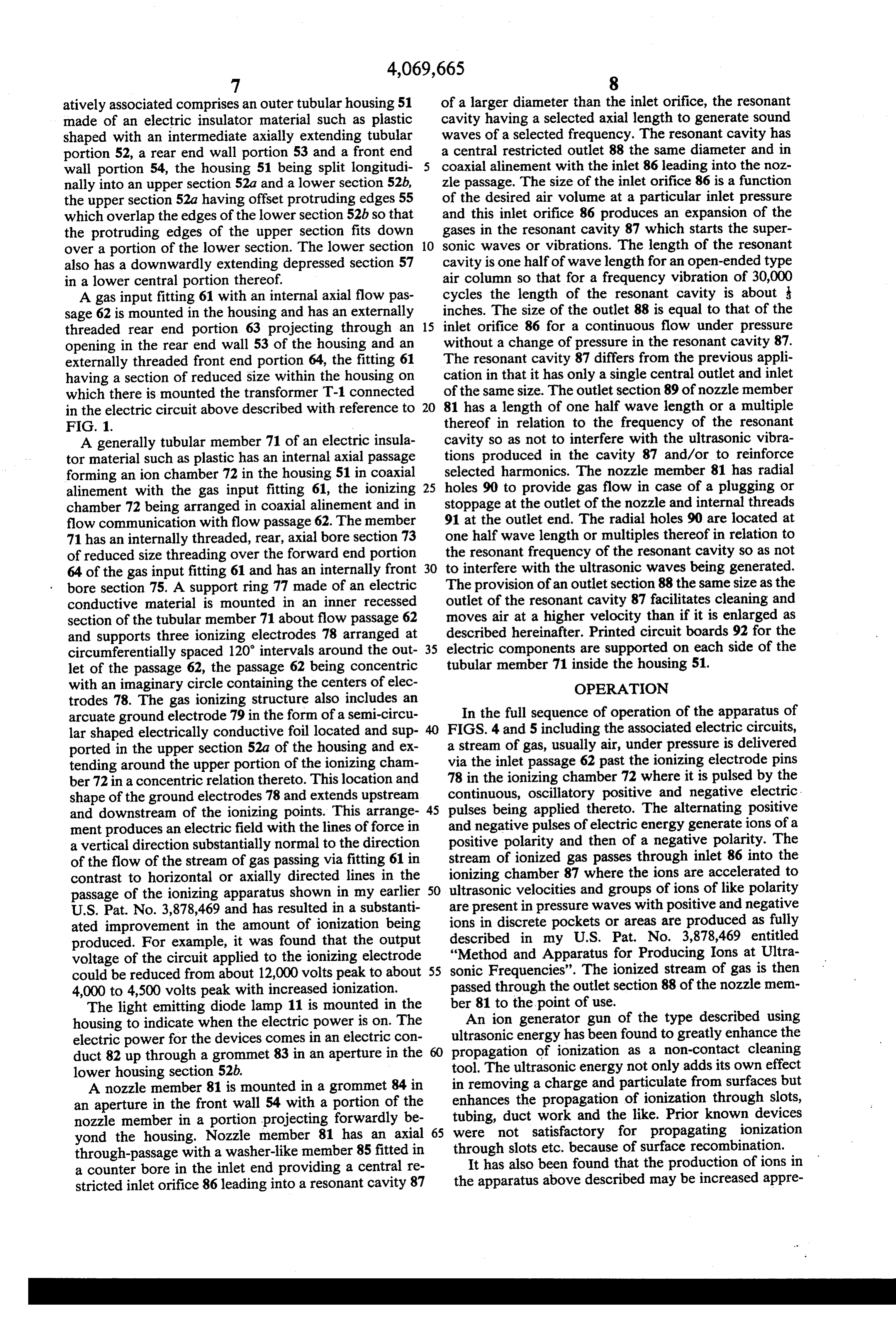
atively associated comprises an outer tubular housing 51 of a larger diameter than the inlet orifice, the resonant made of an electric insulator material such as plastic cavity having a selected axial length to generate sound shaped with an intermediate axially extending tubular waves of a selected frequency. The resonant cavity has portion 52, a rear end wall portion 53 and a front end a central restricted outlet 88 the same diameter and in wall portion 54, the housing 51 being split longitudi coaxial alinement with the inlet 86 leading into the noz nally into an upper section 52a and a lower section 52b, zle passage. The size of the inlet orifice 86 is a function the upper section 52a having offset protruding edges 55 of the desired air volume at a particular inlet pressure which overlap the edges of the lower section 52b so that and this inlet orifice 86 produces an expansion of the the protruding edges of the upper section fits down gases in the resonant cavity 87 which starts the super over a portion of the lower section. The lower section 10 sonic waves or vibrations. The length of the resonant also has a downwardly extending depressed section 57 cavity is one half of wave length for an open-ended type in a lower central portion thereof. air column so that for a frequency vibration of 30,000 A gas input fitting 61 with an internal axial flow pas cycles the length of the resonant cavity is about sage 62 is mounted in the housing and has an externally inches. The size of the outlet 88 is equal to that of the threaded rear end portion 63 projecting through an 15 inlet orifice 86 for a continuous flow under pressure opening in the rear end wall 53 of the housing and an without a change of pressure in the resonant cavity 87. externally threaded front end portion 64, the fitting 61 The resonant cavity 87 differs from the previous appli having a section of reduced size within the housing on cation in that it has only a single central outlet and inlet which there is mounted the transformer T-1 connected of the same size. The outlet section 89 of nozzle member in the electric circuit above described with reference to 20 81 has a length of one half wave length or a multiple F.G. 1. thereof in relation to the frequency of the resonant A generally tubular member 71 of an electric insula cavity so as not to interfere with the ultrasonic vibra tor material such as plastic has an internal axial passage tions produced in the cavity 87 and/or to reinforce forming an ion chamber 72 in the housing 51 in coaxial selected harmonics. The nozzle member 81 has radial alinement with the gas input fitting 61, the ionizing 25 holes 90 to provide gas flow in case of a plugging or chamber 72 being arranged in coaxial alinement and in stoppage at the outlet of the nozzle and internal threads flow communication with flow passage 62. The member 91 at the outlet end. The radial holes 90 are located at 71 has an internally threaded, rear, axial bore section 73 one half wave length or multiples thereof in relation to of reduced size threading over the forward end portion the resonant frequency of the resonant cavity so as not 64 of the gas input fitting 61 and has an internally front 30 to interfere with the ultrasonic waves being generated. bore section 75. A support ring 77 made of an electric The provision of an outlet section 88 the same size as the conductive material is mounted in an inner recessed outlet of the resonant cavity 87 facilitates cleaning and section of the tubular member 71 about flow passage 62 moves air at a higher velocity than if it is enlarged as and supports three ionizing electrodes 78 arranged at described hereinafter. Printed circuit boards 92 for the circumferentially spaced 120 intervals around the out 35 electric components are supported on each side of the let of the passage 62, the passage 62 being concentric tubular member 71 inside the housing 51. with an imaginary circle containing the centers of elec OPERATION trodes 78. The gas ionizing structure also includes an arcuate ground electrode 79 in the form of a semi-circu In the full sequence of operation of the apparatus of lar shaped electrically conductive foil located and sup FIGS. 4 and 5 including the associated electric circuits, ported in the upper section 52a of the housing and ex a stream of gas, usually air, under pressure is delivered tending around the upper portion of the ionizing cham via the inlet passage 62 past the ionizing electrode pins ber 72 in a concentric relation thereto. This location and 78 in the ionizing chamber 72 where it is pulsed by the shape of the ground electrodes 78 and extends upstream continuous, oscillatory positive and negative electric and downstream of the ionizing points. This arrange 45 pulses being applied thereto. The alternating positive ment produces an electric field with the lines of force in and negative pulses of electric energy generate ions of a a vertical direction substantially normal to the direction positive polarity and then of a negative polarity. The of the flow of the stream of gas passing via fitting 61 in stream of ionized gas passes through inlet 86 into the contrast to horizontal or axially directed lines in the ionizing chamber 87 where the ions are accelerated to passage of the ionizing apparatus shown in my earlier 50 ultrasonic velocities and groups of ions of like polarity U.S. Pat. No. 3,878,469 and has resulted in a substanti are present in pressure waves with positive and negative ated improvement in the amount of ionization being ions in discrete pockets or areas are produced as fully produced. For example, it was found that the output described in my U.S. Pat. No. 3,878,469 entitled voltage of the circuit applied to the ionizing electrode "Method and Apparatus for Producing Ions at Ultra could be reduced from about 12,000 volts peak to about 55 sonic Frequencies'. The ionized stream of gas is then 4,000 to 4,500 volts peak with increased ionization. passed through the outlet section 88 of the nozzle mem The light emitting diode lamp 11 is mounted in the ber 81 to the point of use.
housing to indicate when the electric power is on. The An ion generator gun of the type described using ultrasonic energy has been found to greatly enhance the electric power for the devices comes in an electric con propagation duct 82 up through a grommet 83 in an aperture in the of ionization as a non-contact cleaning lower housing section 52b. tool. The ultrasonic energy not only adds its own effect A nozzle member 81 is mounted in a grommet 84 in in removing a charge and particulate from surfaces but an aperture in the front wall 54 with a portion of the enhances the propagation of ionization through slots, nozzle member in a portion projecting forwardly be tubing, duct work and the like. Prior known devices yond the housing. Nozzle member 81 has an axial 65 were not satisfactory for propagating ionization through-passage with a washer-like member 85 fitted in through slots etc. because of surface recombination. It has also been found that the production of ions in a counter bore in the inlet end providing a central re stricted inlet orifice 86 leading into a resonant cavity 87 the apparatus above described may be increased appre
Page 9
ciably by heating the stream of gas (usually air) above PLURALULTRASONIC GENERATORS the usual ambient temperatures. This may be done prior to, during or after ionization and may be done with or Referring now to FIG. 4, there is shown a nozzle without the use of the ultrasonic sound wave generator member 95 having two cascaded ultrasonic generators provided by the resonant cavity 87. in the form of resonant cavities 96 and 97 arranged one In the embodiment shown in FIG. 4A, a heater is after the other in series so that the ionized gas stream provided in the form of a tubular member 93 provided passing from resonant cavity 96 is applied to the reso with a heater element 94 in the form of an electric resis nant cavity 97 with the output gas stream of resonant tor to which an electric potential is applied to heat the cavity 97 then passing into the discharge section i00 of gases passing through member 93. This tubular member 10 the nozzle member 95. In this embodiment resonant is suitably coupled to fitting 61 in FIG. 4 to heat the gas cavity 96 is formed by a cup-like body 98 which inserts prior to entry into the ionizing chamber or to the outlet The into the axial passage of the member 95 at the inlet end. nozzle 8 to heat the ionized gas. cup-like body 98 has a smaller inlet section 99 and For heating during ionization there is shown a modi 15 aalinement larger cavity section 101 formed therein in coaxial with one another.
fied construction in tubular member 71 in FIG. 4B, wherein a layer of insulation 66 is provided in the ioniz body The resonant cavity 97 is formed by a similar cup-like ing chamber 72 and the heater element 94 is mounted cavity102 and has a smaller inlet section 103 and a larger section 104. The body 102 is inserted first into therein to heat the gas during ionization. member 95 and fits against an inside flange 104 forming Referring again the FIG. 1 the heating element 94 is the outlet 107 of the second resonant cavity 97. A re shown as connected in the circuit in series with a ther mal overload device 67, the series circuit being con place inring taining
105 holds the cup-like bodies 98 and 102 in nozzle member 95. The outlet section 100, of nected across input terminals 5 and 6. In this way, when the nozzle member is enlarged relative to outlet 107 so the temperature of the gas moving through the ion that the ionized gases expand and has a plurality of chamber becomes excessive, the heat sensitive contacts 25 radial holes 106. The expansion 67 open, disconnecting the power to the heater and the been found to amplify the loweroffrequency the outlet passage has harmonics, heater 94 cools off until a preselected lower tempera for example 8,000 cycles.
ture is reached at which time the contacts of device 67 The use of multiple ultrasonic cavities as shown in close and the power is applied to the heater element 94. FIG.
This protects the ion generator device against excessive 30 of the9base are useful for either amplification of the energy frequency of the first generator or for ampli temperatures. fying the energy of a selected harmonic of the base In an alternative circuit arrangement for the heater frequency. For example if resonant cavity 96 resonates element shown in FIG. 6 the full line voltage 15 is ap at 24,000 Hz and resonant cavity 97 at 24,000 Hz then plied across the heater element 94 but only a portion of there is simply amplification or energy increase in the the line voltage is applied to the bridge rectifier circuit 35 base frequency. However, if it is desirable to amplify 9 to produce ions by virtue of the use of the tap 94a the energy level of other selected harmonics for certain which takes only a portion of the voltage across ele cleaning purposes then resonant cavity 97 may be con ment 94. This has been found to reduce the cost of structed to resonate at 72,000 Hz and in this way am transistor 18 since a lower voltage transistor may be plify the third harmonic waves produced in the reso used. nant cavity 96.
In another circuit arrangement for the heater element In another form of plural ultrasonic generator ar which is shown in FIG. 1 and designated 94, an isola rangement shown in FIG. 10, the ultrasonic sound wave tion transformer winding 68 is connected in series with energy is applied to the gas in two successive stages the secondary winding 21 at terminal 31 and the heater prior to ionization of the gas. An inner tubular member element 94 is connected across isolation transformer 11 made of an electric insulation material inside the winding 68. This arrangement makes the heating simul housing 51 is coupled to a gas inlet fitting 112 and taneous and syncronized with ionization using for ex carries two cascaded cup-like bodies 113 and 114 form ample the structure of FIG. 4B with the heater in the ing successive ultrasonic resonant cavities 115 and 116, ionizing chamber. respectively, with successive outlets 117 and 118, re In an automatic control for the heater shown in FIG. 50 spectively. An output nozzle member 121 threads into 7, a conventional Triac control member 69 is connected the downstream end of the tubular member 111 forming in series therewith and a conventional electric heat the downstream end wall of a cavity 122 downstream of sensor 70 senses the temperature of the gas. The sensorthe ultrasonic resonant cavities 115 and 116. Three ion 70 controls one of the electrodes of the Triac control izing electrode pins 123 on a conductive ring 124 are member 69 as shown in FIG. 7. The Triac control mem 55 provided in the ionizing cavity 122 which has a re ber 69 functions to clip off a portion of the cycle of the stricted outlet 125 leading into an enlarged discharge AC power as represented by waveform P in FIG. 8 in section 127 of the output nozzle member 121. The elec relation to the temperature being sensed by sensor 70 trode pins are at 120 degree intervals similar to elec and provides substantially constant heat for the stream trodes 78 above described and terminate in ionizing of gas being conveyed through the ion chamber. There points. Again radial holes 126 are provided in the nozzle is further provided in the circuit of FIG. 7 a pressure member at a selected distance along the length thereof. sensitive relay comprised of a contact portion 76 con Another form of ion generator structure with internal nected between terminal 6 and fuse 8, which contact gas heating shown in FIG. 11 has a tubular housing 131 portion is opened and closed by a pressure control por shown as having a circular transverse cross-section with tion 77 coupled in the gas input line leading into the ion 65 a counter bore 132 at each end in which there is pro generator represented at 62 in FIG. 4. The pressure vided at the gas inlet end an inlet fitting 133 having an sensitive relay is set to close the relay portion when gas enlarged disc-like portion fitted in the counter bore and is flowing and open the circuit when gas is not flowing. at externally threaded end portion adapted to receive a
Page 10
pipe fitting to couple gas thereto. The fitting 133 has a outlet chamber 165 and into the ultrasonic generator gas flow passage 134 through which the gas stream (not shown) like chamber 150 above described via out enters and then expands into an inner enlarged chamber let 148. The outlet chamber 165 is heat insulated by a 135 inside housing 131. A helically wound heating coil layer of insulation 160.
136 is wrapped on a ceramic core 137 which in turn is Referring now to FIG. 13, there is shown a modified mounted on a central electrically conductive shaft 138 nozzle member 171 with a resonant cavity 172 formed with core 137 and shaft 138 forming a hub extending at the inlet end and an enlarged nozzle outlet section axially through the central portion of the housing. The 173. This nozzle member 171 may be used with or with helical coil 136 has a plurality of turns each spaced from out the ultrasonic chamber 172 and is used where the one another for additional heating of the gas. A pair of 10 gas is heated. The nozzle member 171 has circumferen axially spaced end plates or discs 139 and 140 fit on the tially spaced outwardly enlarged venturi openings 173 ends of the shaft and are held by nuts 141 preferably characterized by increasing in diameter toward the threading on the ends of the shaft 138. Upstream disc outer end and inclined toward the upstream end. These 139 has a plurality of circumferentially spaced inlet venturi openings 174 draw additional gas into the gas openings 142 spaced at equal intervals forming an inlet 15 stream and have been found effective in increasing the which pass the gas stream from chamber 135 around the volume of gas thereby cooling the gas discharged from coil 136 in a heating chamber 131a and disc 140 has a the nozzle member when the heating of the gas is used. plurality of circumferentially spaced outlet openings The ion generator apparatus shown in FIGS. 11 143 spaced at equal intervals forming an outlet to pass through 13 with the circuit of FIGS. 1 or 3 having the the heated gas from the heating chamber 131a. A layer 20 modification of FIG. 13 has particular application to of insulation 144 is provided along the inside of the electrostatic spray painting wherein a fluidizing bed housing between discs 139 and 140 and spaced out with a fine powder is coupled by a line to the input wardly of the coil 136 to heat insulate the housing 131. fitting 134. The fluidizing bed has a pressure line from a The ionizing chamber 145 is formed in the downstream compressor or like pressure source. The powder passes end portion of the housing 131 beyond downstream 25 plate 140. Three circumferentially spaced ionizing elec through heated input line and over the heating coil 136 to be and is ionized in chamber 145 with a single polar trode pins 146 at 120” like that shown in FIG. 5 are ity pulse, ultrasonically pulsed with sound waves in supported on a conductive ring 147 on the shaft 138. A chamber 150 and then directed by the nozzle member circular plate 155 extends along the inside of the hous 149 to an object being sprayed which is connected at ing 131 and encompasses the ionizing electrode pins 30 ground potential. In the spray gun application the heat forming the ground electrode. The ground electrode ing 155 extends both upstream and downstream of the ion the coils powder 135 are preferably sealed so as not to contact or like particles being sprayed.
izing pins. A layer of insulation 156 heat insulates the Referring now to FIG. 14 there is illustrated schemat ionizing chamber 145. Shaft 138 is electrically conduc ically tive and carries current to conductive ring 147. The 35 engineportions of the conventional internal combustion downstream end of the housing 131 has a disc 148 fitted of air represented vehicle of a motor or the like in which a stream in the counter bore at the outlet of the housing with a cleaner 202 and then through201theis induction by arrows drawn into the air pipe 203 central restricted orifice 148a which forms the down stream end of the ionizing chamber 145. The nozzle which in turn is coupled to the intake side of the engine member 149 at the outlet end of the housing has an rowed to ainside 204. The of the induction pipe is usually nar enlarged cup-shaped portion which fits in the counter to increase reduced the diameter at an intermediate position velocity thereof and the pressure de bore of the housing against disc 148 to form a resonant cavity 150 downstream of the ionizing chamber 145. A creases to suck the fuel out of the carburetor 205 sup smaller diameterbore 151 in nozzle member 149 leading plied by a tank represented at 206, with the fuel being atomized in the induction pipe 203. In the operation of from the ultrasonic resonant cavity 150 and leads into 45 the enlarged outlet passage 152 having radial openings 153. fuel conventional engine, the tiny atomized droplets of are carried along the intake portion of the engine by
The transformer T-1 and circuitry on plates 92 are sup the air stream. As a result of the heat of absorption on ported on a suitable casing structure disposed below the housing 131. The resonant cavity 150 is considerably the way to the cylinder, these droplets are vaporized wider in radial extent than it is long and has been found 50 and the vapor-air fuel mixture enters the combustion to generate additional ultrasonic energy. The shortened inletchamber 208 of the engine. The throttle valve 209 in the nozzle member 149 has a passage 152 selected in length pipe is operated by the accelerator pedal by the so as to eliminate lower or audio frequencies such as operator to regulate the fuel flow. around 8,000 Hz and below. The modification shown in The distributor portion of a conventional internal FIG. 11A includes a pipe section 157 on the inlet end of 55 combustion engine shown schematically in FIG. 14 disc 148 making a passage 159 having a selected length includes contacts shown in the form of an electric in relation to the resonant frequency of the resonant switch 211 with an ignition cam 212 arranged to rotate cavity 150 to increase the energy level. A length of five as the engine rotates and open and close the contacts times the diameter has been found highly effective. 211 in accordance with the ignition timing. A capacitor A modified ion generator structure shown in FIG. 12 213 is connected across the contacts 211 to prevent has a conductive ring 161 connected on shaft 138 and sparking.
normally
In this arrangement, the coil of the vehicle supplying spark for the spark plugs and repre held by a nut 162 so that the ionizing pins 163 are car ried by the upstream plate and are located inside the sented at T-3 is used as the transformer to increase the heating chamber 131a. In this way the gas stream passes electrical power for generating positive and negative between electric ground and the pins 163 and heating 65 ions. The coil T-3 has a primary winding 214 and two takes place substantially simultaneously with ionization. secondary windings designated 215 and 216 wound on a A ground electrode plate 159 is spaced outwardly of the common core 217. Preferably, the vehicle battery desig ionizing electrode pin 163. The heated ions pass into an nated 218 is utilized as the source of electric power. The
Page 11
battery voltage is applied to the contacts 211 via a resis The ionizing electrode assembly 240 contained in the tor 22. air filter 202 is shown in detail in FIGS. 16 and 17 in A control circuit is operatively coupled between the cludes a high voltage conductive metal ring 241 with a battery 28, contacts 211 and primary winding 216 to plurality of ionizing electrode pins 242 secured at alternately couple and uncouple the power from the 5 equally spaced intervals around the periphery of the battery to the primary winding via the contacts 211. ring 241. The output of the secondary winding 215 is The control circuit includes a voltage divider com coupled to the inner ring 231 via a line 228 to convey prised of resistor 222, potentiometer 223 and resistor the ionizing power to the ionizing points. The ring 241 224 is connected across the battery 218. A transistor 225 passes through a plurality of upright support spacers has its collector and emitter electrodes connected be 10 243 made of a non-conductive material arranged along tween the output of the voltage divider and the collec the middle of the inner side edges thereof. Upper and tor electrode of a second transistor 226 to serve as a lower metal ground plates 244 and 245 pass through the voltage regulator as it the circuit of FIG. 1A. The emit support spacers at the outer side edges. As best seen in ter electrode of transistor 226 is connected to the un FIG. 16, there are six spacers 243 at about 60 degree grounded side of the primary winding 214. The base 15 intervals and twenty ionizing pins 242 arranged at eigh electrode of transistor 225 is connected to a center tap teen degree intervals. This places the ionizing points on potentiometer 223 so that a change in the setting of midway between the upper and lower ground plates 244 the tap on potentiometer 223 varies the output voltage and 245. In operation, the ionizing assembly is placed of the secondary winding. The base electrode of transis inside the center of the air filter of the vehicle so that tor 226 is connected between contacts 211 and resistor 20 the incoming air passing into the induction pipe 203 221. In this way contacts 211 control the conduction of passes through an electric field between the ionizing the transistor 226 and the energization of winding 24. points and ground plates and is ionized. As long as the contacts 211 are closed current flows in The exhaust manifold represented diagrammatically the primary winding 214 and a magnetic field is formed at 246 in FIG. 14 is provided with one or more ionizing in the coil core 217. At the instant when the cam 212 25 pins 251 in the exhaust manifold for the purpose of interrupts the primary current by opening the contacts breaking up the hydrocarbons, nitrons oxide products 211 this magnetic field breaks and the sudden change of and promote the formation of water, oil, and carbon the magnetic field induces a voltage in the secondary dioxide. To this end the ionizing electrode pins 251 windings 215 and 216 which in normal engine operation shown are mounted on a manifold gasket 252 shown in produces a spark in the spark plugs of the vehicle. A 30 detail in FIGS. 18 and 19. The manifold gasket has double pole, double throw reversing switch 227 is cou openings with a cross-shaped central section 254 on pled between the secondary winding 215 and the elec which there is mounted an ionizing pin 251. A power trode assembly in air filter 202 to reverse the polarity of supply line connects to each of the pins to carry the the pulses applied thereto. current from the secondary winding of the coil. A Additional ignition timing of the engine is controlled 35 ground electrode ring 255 surrounds or encircles each by a negative pressure in the induction pipe 203 behind of the ionizing electrode pins and fits into the head or the throttle valve 209 which is normally transmitted by block of the engine in a frictional engagement therewith linkage to the contact-breaker plate inside the distribu to ground the electrode ring or the head or block itself tor. This linkage includes a tubular section 231 opening may be directly used as the ground. into the induction pipe 203, a diaphram 232 connected 40 An alternative to the locations of several ionizing to a linkage bar. 233 and a diaphram spring 234 biasing points at the ports of the exhaust manifold is to provide the diaphram in one direction. The linkage bar 233 is an exhaust gasket 258 at the end of the manifold where coupled to the movable tap on potentiometer 223 via a it connects to the tailpipe with a cross-section over the conventional linear-to rotary motion converter 235 port and a single ionizing electrode pin 259 with a sur coupled to the movable tap so that as the ignition timing 45 rounding ground electrode ring 260. is altered there is a change in the setting of the tap on Although the present invention has been described potentiometer 223. with a certain degree of particularity, it is understood In the operation of the circuit of FIG. 14 and with that the present disclosure has been made by way of reference to the waveform of FIG. 15, when contacts example and that changes in details of structure may be 211 are open transistor 226 turns on and current flows in 50 made without departing from the spirit thereof. What is claimed is:
winding 214 producing a positive pulse P. When the contacts close there is some time delay d-1 before the 1. In apparatus for improving the operation of an positive pulse reaches zero and then there is a negative internal combustion engine having an exhaust system flyback pulse N for a time duration designated "n'. inclusive of a manifold and an exhaust pipe for discharg When contacts 211 are again opened there is another 55 ing the products of combustion, an ignition system in time delay d-2 before another positive pulse Pappears cluding contacts and an ignition cam that opens and followed by a negative pulse N. Each positive pulse and closes the contacts as the engine is rotated, and a coil for negative pulse produces positive and negative ions in producing a spark in a combustion chamber including a the air stream passing through the air filter 202 and in primary winding and a secondary winding wound on a the exhaust gases at the manifold 246 by its application common core, and a power source on the vehicle for to one or more ionizing electrodes as described hereaf providingcomprising:
electric power to the coil, the combination ter.
It is understood that while the coil of the vehicle control circuit means coupled between the power affords a convenient generator for producing periodic source and primary winding of the coil to alter oscillatory pulses of electric energy, that the circuits of 65 nately couple and uncouple the electric power to FIGS. 1 through 8 may also be used to apply the pulses the primary winding to produce continuous oscilla generated therein to the electrode assemblies in the air tions of repetitive positive and negative pulses of cleaner or in the exhaust system. electric energy at a voltage sufficiently low to
Page 12
avoid the production of ozone, said control circuit transistor and a second transistor each having emit means having a voltage divider including a potenti ter base and collector electrodes, said first transis ometer having a tap, said potentiometer being con tor and second transistor being cascaded between nected across said battery, a first transistor and a the voltage divider and the primary winding, the second transistor each having emitter base and base of the first transistor being connected to a tap collector electrodes, said first transistor and second on a potentiometer in the voltage divider and the transistor being cascaded between the voltage di base electrode of the second transistor being con vider and the primary winding, the base of the first nected to the contacts whereby to alternately open transistor being connected to a tap on a potention and close the contacts to conduction and noncon eter in the voltage divider and the base electrode of 10 duction of the transistors;
the second transistor being connected to the an electrode assembly in the air cleaner in proximity contacts whereby to alternately open and close the to the air stream drawn into the induction tube contacts to conduction and non-conduction of the including at least one ionizing electrode coupled to transistors, and the secondary winding together with a ground an ionizing electrode assembly in proximity to the 15 electrode spaced from the ionizing electrode for exhaust gases including at least one ionizing elec applying said pulses of electric energy to the air trode coupled to the secondary winding together stream into the induction pipe to ionize said air with a ground electrode spaced from the ionizing stream with a minimum of ozone prior to combus electrode for applying said electric energy to the tion of the fuel, exhaust gases to generate ions in the stream of 20 said electrode assembly including a conductive ioniz exhaust gases substantially free of ozone to break ing ring connected to the secondary winding hav up the products of combustion. ing a plurality of pin-like ionizing electrodes at 2. In apparatus as set forth in claim 1 wherein said spaced intervals around the ring and radiating out ionizing electrode is centered in a port in the exhaust wardly from the ring, an upper conductive ground manifold. 25 ring spaced above said ionizing ring and a lower 3. In apparatus as set forth in claim 1 wherein said conductive ground ring spaced below said ionizing ionizing electrode is centered in the exhaust pipe. 11g;
4. In apparatus for improving the operation of an a plurality of upright support spacers made of a non internal combustion engine having an exhaust system conductive material for supporting said ionizing including a manifold and an air cleaner associated with 30 ring and said upper and lower ground rings in an induction pipe into which air is drawn to produce vertically spaced relation to one another in the air combustion in the combustion chamber, an ignition cleaner; and system including contacts and an ignition cam that a reversing switch between said secondary winding opens and closes the contacts as the engine is rotated, a and said electrode assembly to change the polarity coil for producing a spark in the combustion chamber 35 of the ions.
including a primary winding and a secondary winding 5. In apparatus as set forth in claim 4 further includ wound on a common core, and a power source for ing a second secondary winding on said core and a providing electric power to the coil, the combination second electrode assembly in proximity to the exhaust comprising: gases of the engine, said second electrode assembly control circuit means coupled between the power 40 including a second ionizing electrode coupled to said source, contacts and primary winding of the coil to second secondary winding and a second ground elec alternately couple and uncouple the electric power trode spaced from said second ionizing electrode. to the primary winding via said contacts to pro 6. In apparatus as set forth in claim 5 wherein said duce continuous oscillations of repetitive positive second ionizing electrode in a pin-like conductive mem and negative pulses of electric energy at a voltage ber located in the exhaust manifold.
sufficiently low to avoid the production of ozone, 7. In apparatus as set forth in claim 5 wherein said said control circuit means having a voltage divider second ionizing electrode is a pin-like conductive men including a potentiometer having a tap, said poten ber located in the exhaust pipe.x tiometer being connected across said battery, a first
Provenance
- Collection
- Cited prior art
- Original PDF
- patentimages.storage.googleapis.com →
- Filed
- 1975-11-24
- Pages
- 12
- Method
- pdftotext (the PDF's own text layer) + pdftoppm 300dpi page scans
- Source
- Google Patents bibliographic record
- Granted
- 1978-01-24
- Inventors
- Robert E. Bolasny; Scientific Enterprises Inc
- Transcribed from
- patentimages.storage.googleapis.com →