patent · US5775091
Hydrogen fueled power plant
7 July 1998
Page 1 — bibliographic record
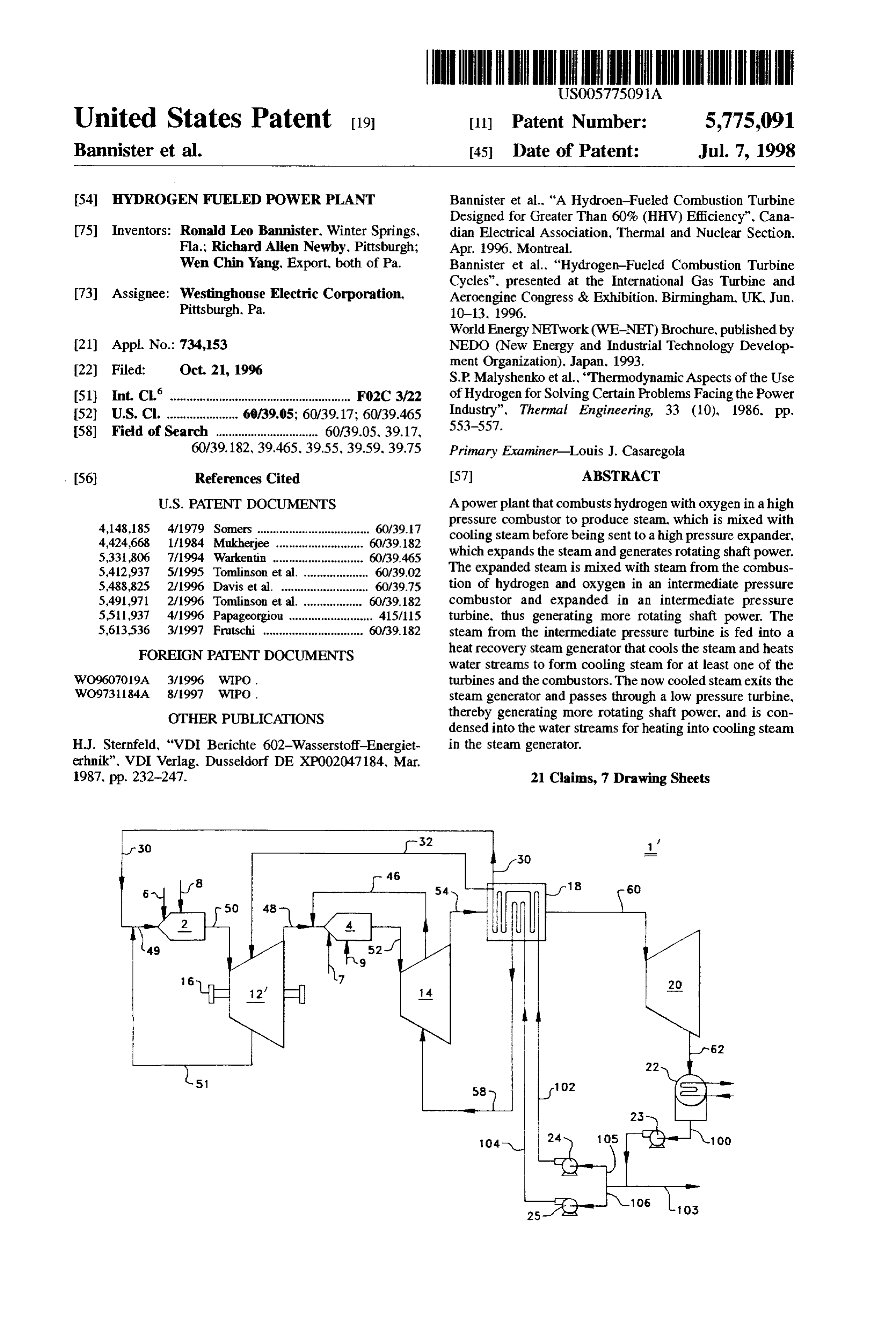
United States Patent 19 11 Patent Number: 5,775,091 Bannister et al. 45 Date of Patent: Jul. 7, 1998 54 HYDROGEN FUELED POWER PLANT Bannister et al., “A Hydroen-Fueled Combustion Turbine Designed for Greater Than 60% (HHV) Efficiency". Cana 75) Inventors: Ronald Leo Bannister. Winter Springs, dian Electrical Association, Thermal and Nuclear Section, Fla.; Richard Allen Newby, Pittsburgh; Apr. 1996, Montreal.
Wen Chin Yang, Export, both of Pa. Bannister et al., "Hydrogen-Fueled Combustion Turbine Cycles", presented at the International Gas Turbine and 73) Assignee: Westinghouse Electric Corporation, Aeroengine Congress & Exhibition, Birmingham, UK, Jun. Pittsburgh, Pa. 1O-3, 1996.
World Energy NETwork (WE-NET) Brochure, published by 21 Appl. No.: 734,153 NEDO (New Energy and Industrial Technology Develop ment Organization). Japan. 1993.
22 Filed: Oct 21, 1996 S.P. Malyshenko et al., “Thermodynamic Aspects of the Use (S1) int.C. ....................... FO2C 3/22 of Hydrogen for Solving Certain Problems Facing the Power 52 U.S. C. ............... ... 60/39.05; 60/39.17; 60/39.465 Industry". Thermal Engineering, 33 (10), 1986, pp. 58 Field of Search ................................ 60/39.05, 39.17, 553-557.
60/39. 182, 39.465. 39.55, 39.59, 39.75 Primary Examiner-Louis J. Casaregola . 56) References Cited 57 ABSTRACT
4,148,185 4/1979 Somers ................................... 60/39.7 pressure combustor to produce steam, which is mixed with 4,424,668 1/1984 Mukherjee ........................... 6039.82 cooling steam before being sent to a high pressure expander, 5.331,806 7/1994 Warkentin ............................ 60/39.465 which expands the steam and generates rotating shaft power. 5,412,937 5/1995 Tomlinson et al. . ... 60/39.02 The expanded steam is mixed with steam from the combus 5,488.825 2/1996 Davis et al. ... ... 60/39.75 tion of hydrogen and oxygen in an intermediate pressure 5,491.971 2/1996 Tomlinson et al. . ... 60/39.182 combustor and expanded in an intermediate pressure 5,511.937 4/1996 Papageorgiou .......................... 41.5/5 turbine, thus generating more rotating shaft power. The 5,613.536 3/1997 Frutschi ............................... 60/39.182 steam from the intermediate pressure turbine is fed into a FOREIGN PATENT DOCUMENTS heat recovery steam generator that cools the steam and heats water streams to form cooling steam for at least one of the
WO960709A 3/1996 WIPO turbines and the combustors. The now cooled steam exits the WO973.1184A 8,997 WTPO. Steam generator and passes through a low pressure turbine, OTHER PUBLICATIONS thereby generating more rotating shaft power, and is con densed into the water streams for heating into cooling steam
H.J. Sternfeld, “VDI Berichte 602-Wasserstoff-Energiet in the steam generator.
erhnik". VDI Verlag. Dusseldorf DE XPO02047.184, Mar.
1987, pp. 232-247. 21 Claims, 7 Drawing Sheets
Page 2
Drawing sheet — no readable text.
Page 3
Drawing sheet — no readable text.
Page 4
Drawing sheet — no readable text.
Page 5
Drawing sheet — no readable text.
Page 6
Drawing sheet — no readable text.
Page 7
Drawing sheet — no readable text.
Page 8
Drawing sheet — no readable text.
Page 9
HYDROGEN FUELED POWER PLANT in the steam generator and becomes a fifth flow of process steam, which is fed into a low pressure turbine. The low
BACKGROUND OF THE ENVENTION pressure turbine generates rotational shaft power and 1. Field of the Invention releases the expanded fifth flow of process steam as a sixth flow of process steam. The sixth flow of process steam is
The present invention relates to a power plant using condensed, the excess water bled off, and the remaining hydrogen and oxygen as the fuel. water is pumped to the steam generator to become cooling 2. Description of the Related Art Steam.
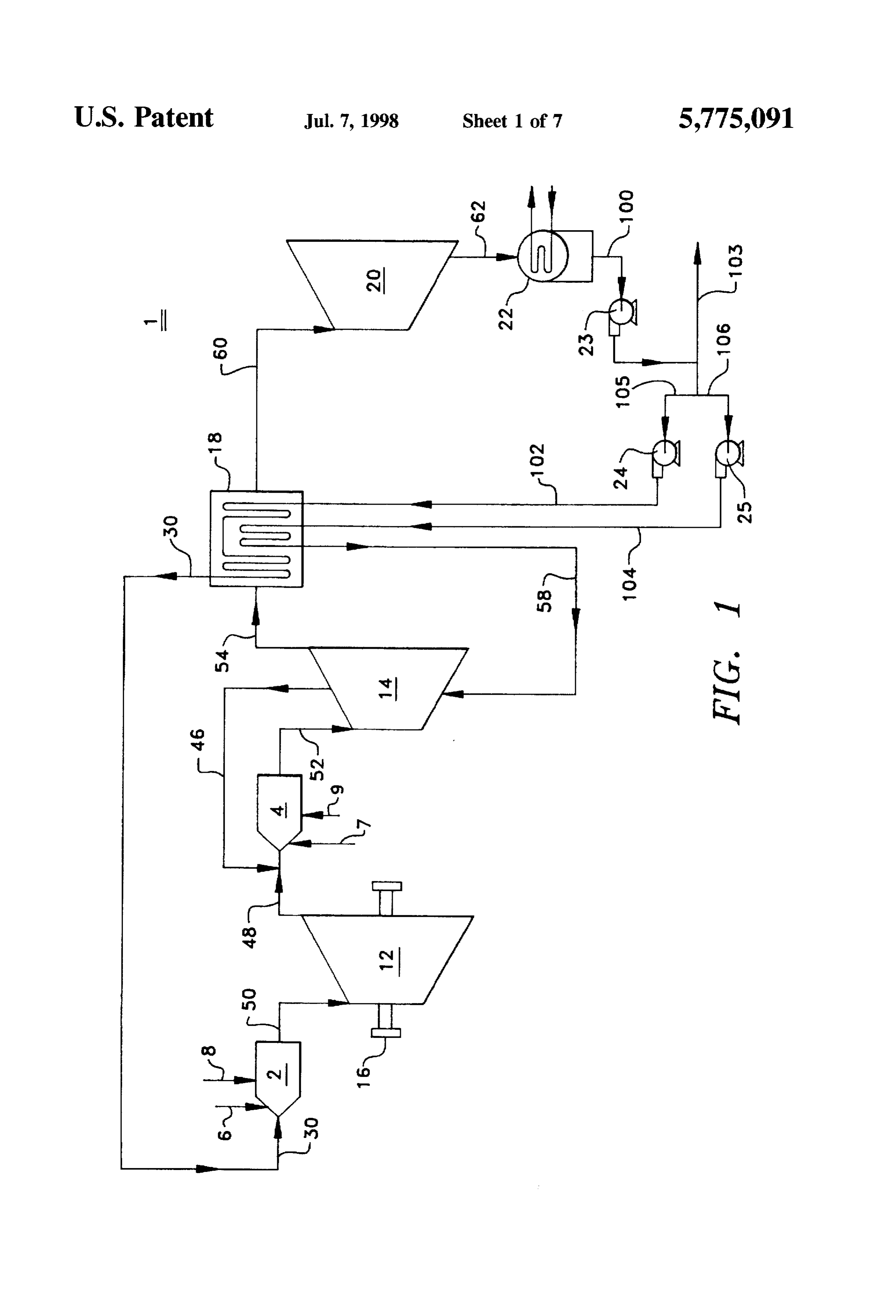
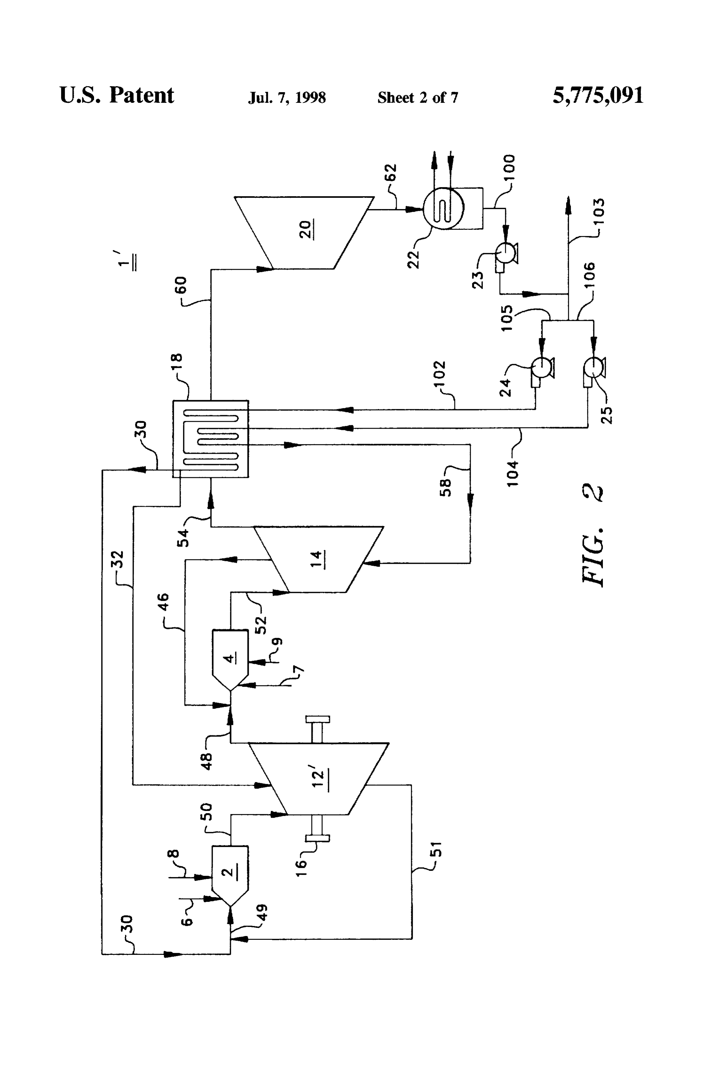
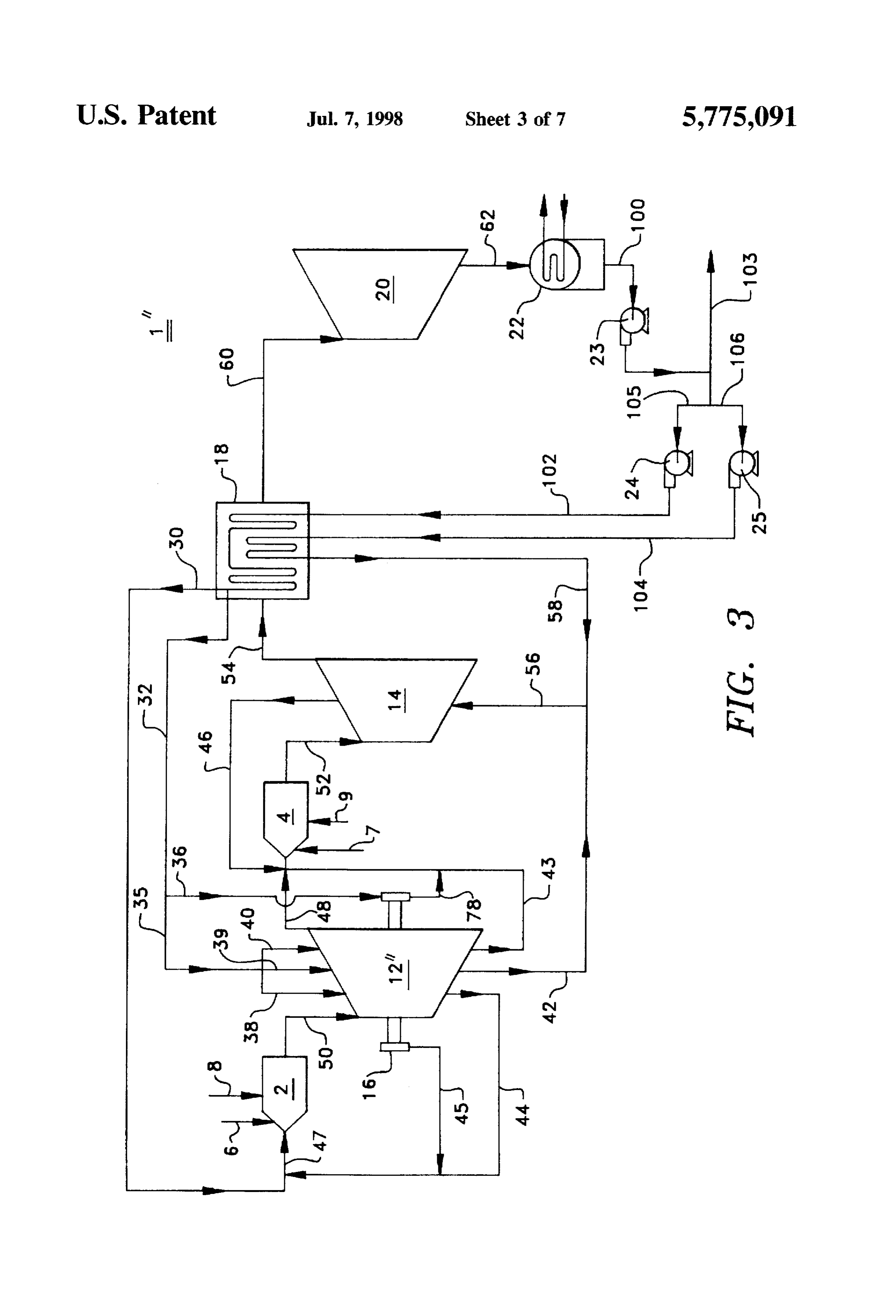
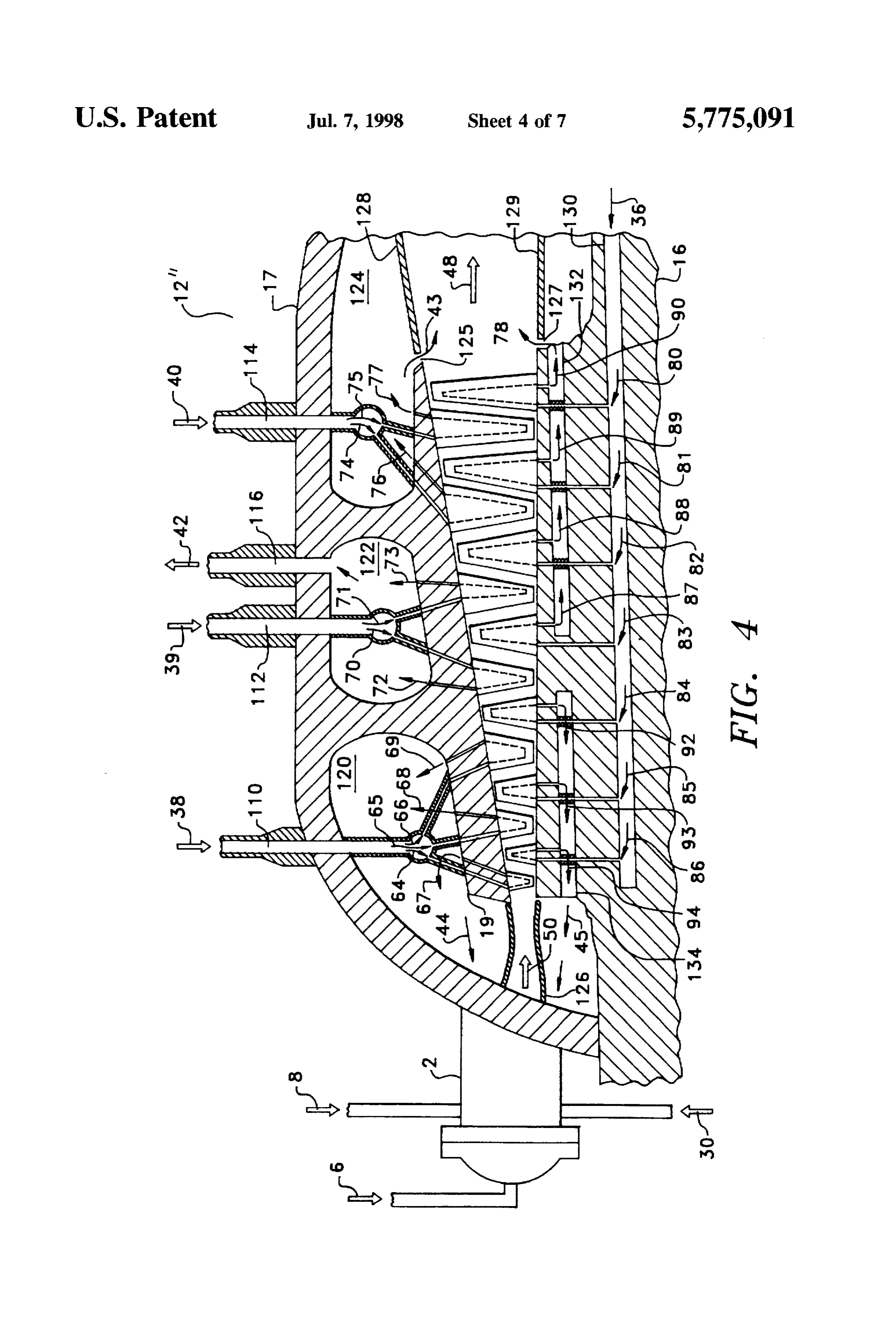
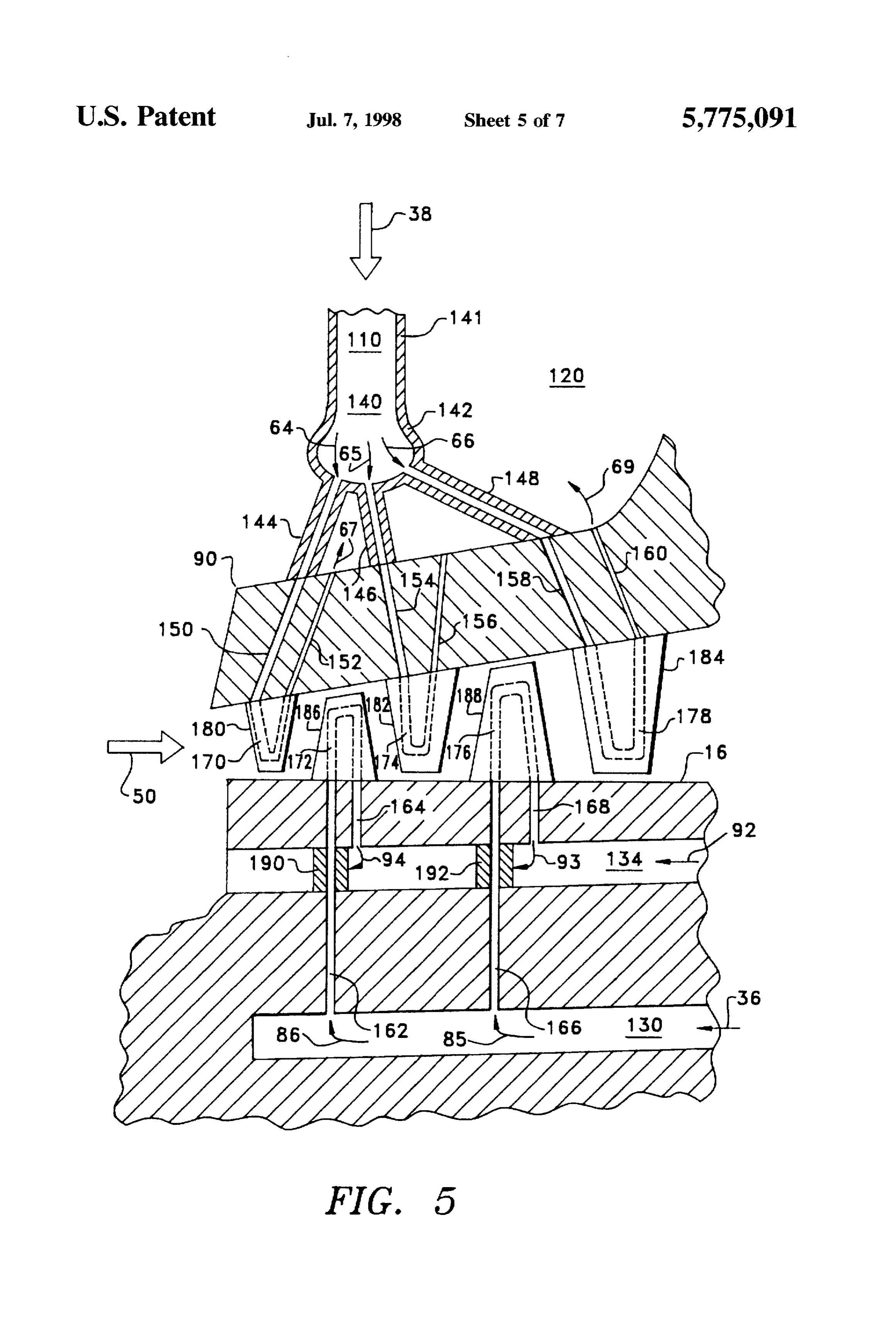
Power plants have a combustion section where a hydro carbon fuel, such as distillate oil or natural gas, is mixed 10 BRIEF DESCRIPTION OF THE DRAWINGS with and burned in the compressed air in one or more FIG. 1 is a schematic diagram of a hydrogen fueled power combustors. Unfortunately, such combustion results in the plant employing a closed-loop steam cooling system in the formation of oxides of nitrogen ("NOx"), carbon dioxide intermediate pressure turbine. (CO), carbon monoxide (CO), and other trace constituents FIGS. 2 and 3 are a schematic diagram of a hydrogen considered atmospheric pollutants. Combusting hydrogen in 15 pure oxygen eliminates the formation of NOx, CO, CO, and fueled power plant employing closed-loop steam cooling other trace constituents considered atmospheric pollutants. system in the high and intermediate pressure turbines. Combustors for rocket engines have traditionally operated FIG. 4 is a longitudinal cross-section, partially schematic, by combusting liquid hydrogen in liquid oxygen. However. through the high pressure turbine shown in FIG. 3. power turbines must operate for extended periods of time FIG. 5 is an enlarged view of FIG. 4 in the vicinity of the without deterioration. Consequently, the problems of cool turbine inlet.
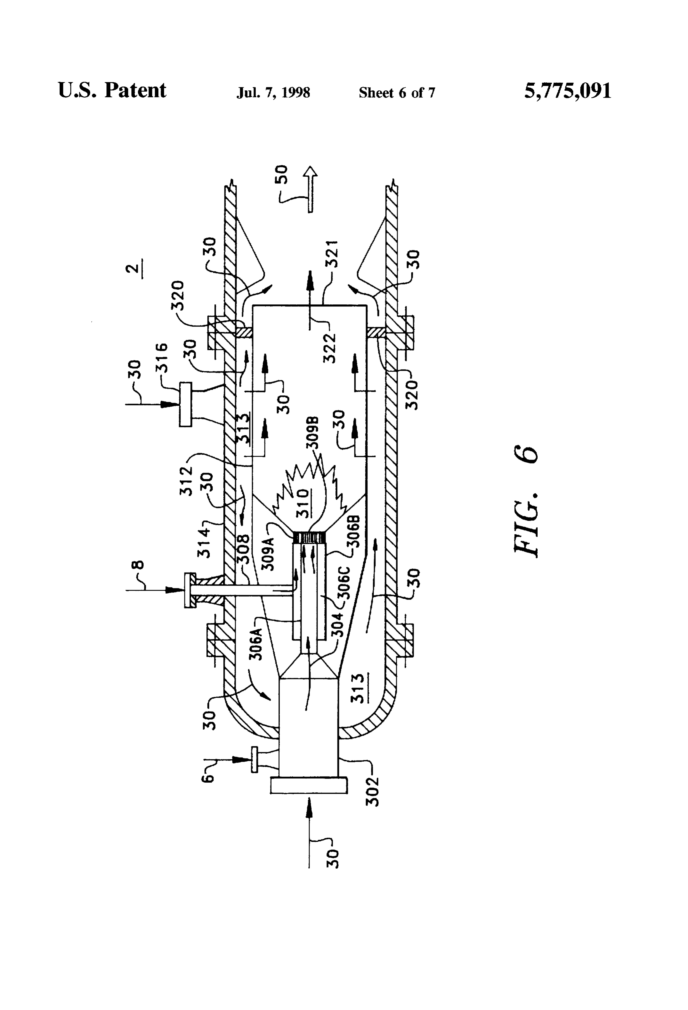
ing the combustor in a gas turbine presents challenges not FIG. 6 is a schematic sectional view of a high pressure present in rocket combustors. This problem is exacerbated combustor.
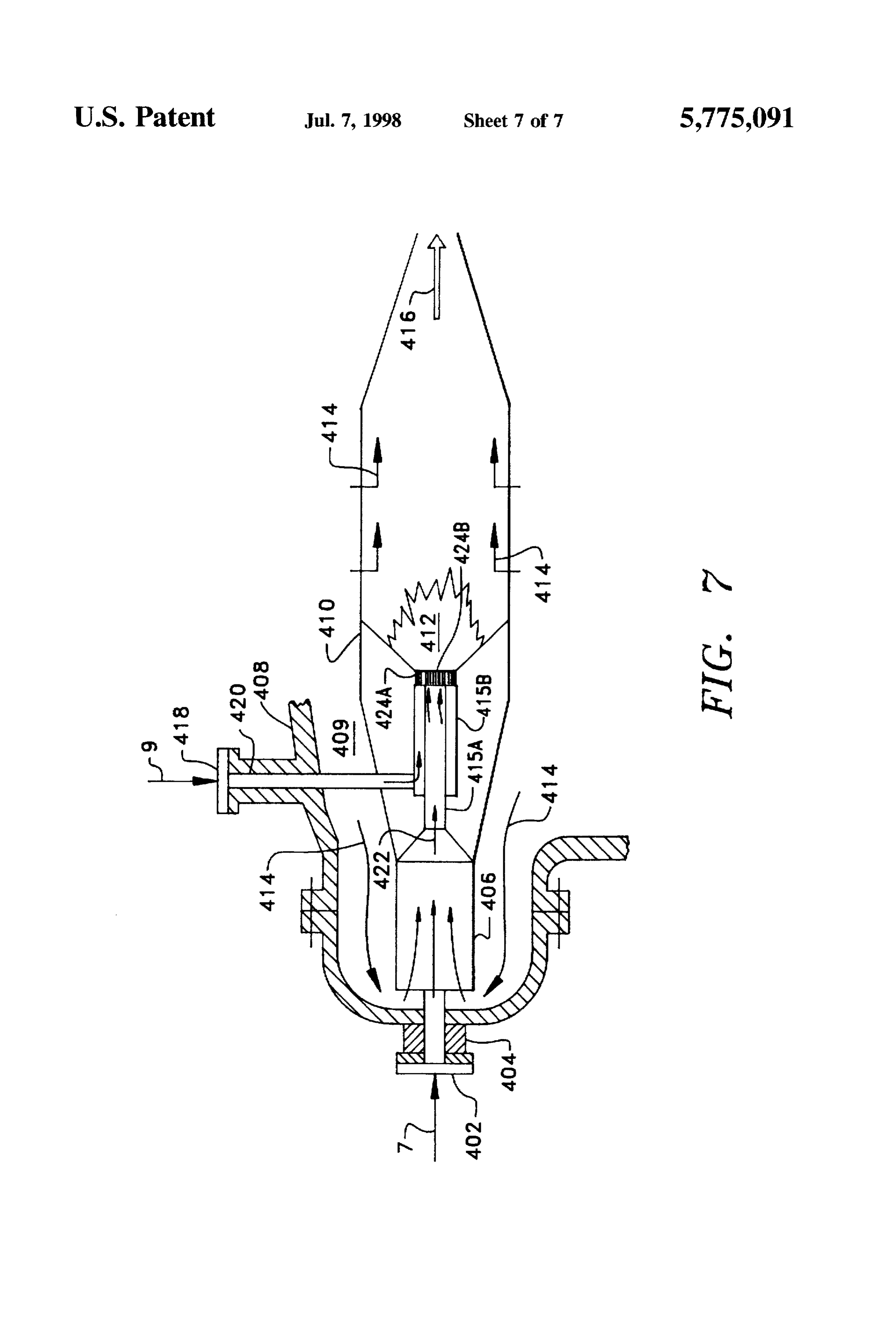
if, for reasons of economy and ease of handling and supply, FIG. 7 is a schematic sectional view of an intermediate compressed oxygen gas, rather than liquid oxygen, is used. pressure combustor.
Typically, rocket combustors rely on the low temperature of liquid oxygen for cooling. DESCRIPTION OF THE PREFERRED Cooling of the turbine section is also a problem in a EMBODIMENT hydrogen/oxygen fueled power plant, especially since it is desirable to operate the turbine with inlet temperatures as Referring to the drawings, wherein like reference numer high as 900 to 1600° C. in order to achieve optimum power als refer to like elements, there is shown in FIG. 1 a output. The cooling traditionally used in combustion tur hydrogen fueled power plant 1. The major components of bines negatively impacts the efficiency of the power plant. the plant 1 are a high pressure combustor 2, a high pressure steam turbine 12 through which a rotor shaft 16 extends, an
It is, therefore, desirable to provide a high efficiency 35 intermediate power plant that generates energy from the combustion of steam turbinepressure14, a combustor 4, an intermediate pressure heat recovery steam generator 18, a low hydrogen and oxygen. pressure steam turbine 20, and a condenser 22. As is typical, SUMMARY OF THE INVENTION each of the turbines drives a load, such as an electrical generator (not shown).
Accordingly, it is the general object of the current inven The high pressure combustor 2 receives a first flow of tion to provide a hydrogen combustion power plant for hydrogen 6 and a first flow of oxygen 8, which may be in effectively and efficiently cooling turbine components with either gaseous or liquid-i.e., cryogenic-form. If the an open- or closed-loop steam cooling system. hydrogen 6 and oxygen 8 are in gaseous form, compressors Briefly, this object, as well as other objects of the current may be utilized to pressurize the gas. In the high pressure invention, is accomplished in a method of generating rotat 45 combustor 2. the hydrogen 6 and oxygen 8 combust to form ing shaft power by feeding a first flow of cooling steam, high temperature, high pressure steam. Preferably, the com hydrogen. and oxygen into a high pressure combustor and bustion takes place at close to stoichiometric conditions so combusting the hydrogen and oxygen to form a high pres that the combustion results in essentially pure steam. A first sure steam. The high pressure steam is cooled with the first flow of cooling steam 30, generated as discussed below, is flow of cooling steam to produce a first flow of process 50 also supplied to the high pressure combustor 2. The cooling steam. The first flow of process steam is expanded in a high steam 30 mixes with the steam produced by the combustion pressure turbine, thereby generating a second flow of pro of the hydrogen 6 and oxygen 8. thereby preventing over cess steam and rotating shaft power. The second flow of heating of the combustor 2 components and producing a first process steam is mixed with a third flow of cooling steam flow of process steam 50. Now referring to FIG. 6, in the from an intermediate pressure turbine and fed into an 55 preferred embodiment of the invention, a portion of the intermediate pressure combustor, where it is mixed with cooling steam 30 and the hydrogen 6 are premixed in an inlet steam from the combustion of hydrogen and oxygen in the chamber 302 of the combustor 2, thus forming a low value intermediate pressure combustor to form a third flow of heating fuel 304. The fuel 304 flows through an axially process steam. The third flow of process steam is fed into the located tube 306A which is surrounded by a tube 30.6B to intermediate pressure turbine to form a fourth flow of form annulus 306C. Oxygen 8 flows through the radially process steam and generate rotating shaft power. The inter located tube 308 to enter annulus 306C. The fuel and oxygen mediate pressure turbine is cooled by a second flow of flow through swirlers 309A and 309B, creating an intensely cooling steam, which exits the turbine as the third flow of back-mixed combustion zone 310 that produces combustion cooling steam. The fourth flow of process steam is passed products 322. The temperature in the combustion zone being through a heat recovery steam generator to heat up two 65 approximately 1600° C. Another portion of the steam 30 streams of feed water to produce the first and second flows passes into the combustor through an orifice 316 and circu of cooling steam. The fourth flow of process steam is cooled lates in a space 313 between the shell 314 and the liner 312,
Page 10
thereby cooling the liner. The liner 312 is also cooled by thermal efficiency. The upper temperature limit of approxi some of the steam 30 passing therethrough. The majority of mately 1700° C. is the limit of a steam cooled turbine. steam 30 in the space 313 passes through swirlers 320 Preferably, the temperature of the third flow of process surrounding outlet 321 of the combustion zone 310, thereby steam 52 is approximately 1700° C. The pressure range of diluting the combustion products 322 exiting therefrom and the third flow of process steam 52 enables good thermal forming the first flow of process steam 50. efficiency and work based on previous commercial use of Now referring to FIG. 1. the mass flows into the high steam turbines. Preferably, the pressure of the third flow of pressure combustor 2 are such that the first flow of process process steam 52 is approximately 39 bar. steam 50 has a temperature range of 500° C. to 900° C. and The intermediate steam turbine 14 receives the third flow a pressure range of 200 bar to 500 bar. The lower tempera O of process steam 52 discharged from the intermediate com ture limit of 500° C. is the minimum required to achieve a bustor. The process steam 52 is then expanded, thereby good overall plant heat rate. The upper temperature limit of producing additional shaft power and a fourth flow of 900° C. is the maximum for the high pressure turbine 12 to process steam 54. Preferably, the process steam 54 dis operate without cooling. Turbine 12 cooling is made redun 5 charged from the intermediate pressure turbine 14 is dant at the upper end of the temperature range through the approximately 1 bar.
use of advanced alloys in the fabrication of the turbine. The heat recovery steam generator 18 receives the fourth Preferably, the temperature of the first flow of process steam flow of process steam 54 from the intermediate turbine 14. 50 is approximately 650° C. The pressure range of the first Within the steam generator 18, a portion of the heat of the flow of process steam 50 enables good thermal efficiency process steam 54 is transferred to a high pressure feedwater and work based on previous commercial use of steam stream 102 and a low pressure feedwater stream 104. This turbines. Preferably, the pressure of the first flow of process transfer of heat cools the fourth flow of process steam 54 steam 50 is approximately 300 bar. which is released from the steam generator as a fifth flow of The high pressure steam turbine 12 receives the first flow process steam 60. Preferably, sufficient heat is transferred in of process steam 50 from the high pressure combustor 2. the heat recovery steam generator 18 so that the process Preferably, the combustor 2 is located external to the turbine 25 steam 60 discharged therefrom has been cooled to approxi 12 but closely coupled with the turbine 12. The process mately 110° C.
steam 50 is expanded in turbine 12, thereby generating shaft The heat recovery steam generator 18 also produces the power in the rotor shaft 16 and producing a second flow of first flow of cooling steam 30 from the high pressure process steam 48. Preferably, turbine 12 has 12 rows of 30 feedwater stream 102 and the second flow of cooling steam blades whose heights vary from approximately 0.9 to 58 from the low pressure feedwater stream 104, as described approximately 2.6 inches. The process steam 48 is dis below. The first flow of cooling steam 30 is sent to the high charged from the high pressure turbine 12 at approximately pressure combustor 2 at approximately 440° C. and approxi 40 bar, a pressure suitable for the intermediate pressure mately 470 bar.
combustor 4. 35 The second flow of cooling steam 58 is used to cool the The intermediate pressure combustor 4 receives the sec intermediate pressure turbine 14. In the embodiment of the ond flow of process steam 48 after is mixed with a third flow invention shown in FIG. 1, the intermediate pressure turbine of cooling steam 46, which is produced as discussed below. 14 has a closed-loop steam cooling system, as described The intermediate pressure combustor 4 also receives a below and shown in FIGS. 4 and 5. In a closed-loop steam second flow of hydrogen 7 and a second flow of oxygen 9 cooling system, the cooling steam flows through the com that is combusted therein into steam. The steam is mixed ponents of the turbine without coming into contact with the with the process steam 48 and the cooling steam 46, thereby process steam being expanded in the turbine. Therefore, as preventing overheating of the combustor 4 components and the second flow of cooling steam 58 flows through the producing a third flow of process steam 52. turbine 14, it is heated and flows out of the turbine as the Referring now to FIG. 7, in the preferred embodiment of 45 third flow of cooling steam 46. With a closed-loop steam the invention, intermediate pressure combustor 4 receives cooling system, the second flow of cooling steam 58 is hydrogen 7 through an orifice 402 of an axially located tube approximately 260° C. and approximately 45 bar. 404. The combustor 4 also receives cooling steam 46 and In other embodiments of the invention, turbine 14 has an process steam 48 (not shown), which is combined into steam open-loop steam cooling system. An open-loop steam cool 414. Steam 414 flows through a space 409 between shell 408 50 ing system cools the stationary vanes or the rotating blade and liner 410 of the combustor, cooling the combustor. A airfoils in a turbine by flowing cooling steam through the portion of the steam 414 flows through the liner 410, cooling components and into the process steam flowing through the the liner. The remainder of the steam 414, and the hydrogen turbine. Typical open-loop steam cooling of these turbine 7, flows into a premixing chamber 406 to form a low value components is disclosed in the commonly assigned U.S. Pat. fuel 422. The fuel 422 passes out of the chamber 406 and 55 No. 5488,825 to Davis et al. entitled "Gas Turbine Vane through an axially located tube 415A which is surrounded by with Enhanced Cooling," and U.S. Pat. No. 5,511.937 to a tube 415B. The radially located tube 420 delivers oxygen Papageorgiou entitled "Gas Turbine Airfoil with a Cooling 9 to the tube 415B. The oxygen is delivered into radially Air Regulating Seal," both of which are incorporated by located tube 420 by an orifice 418. The streams of oxygen reference herein in their entireties. As the cooling steam 9 and fuel 422 flow through swirlers 424A and 424B, flows into the process steam, there is no third flow of cooling creating an intensely back-mixed zone 412 that produces steam 46 in the embodiment of the invention having an combustion products 416. open-loop steam cooling system in intermediate pressure Referring now to FIG. 1, the third flow of process steam turbine 14 (not shown). The operating parameters of the 52 has a temperature range of approximately 1500° C. to hydrogen fueled power plant 1 with an open-loop cooling approximately 1700° C. and a pressure range of approxi 65 system in the intermediate pressure turbine 12 will need to mately 20 bar to approximately 40 bar. The lower tempera be modified from the operating parameters of the plant with ture limit of approximately 1500° C. is to achieve good a closed-loop steam cooling system in the turbine.
Page 11
The low pressure turbine 20 receives the fifth flow of The operating parameters of the hydrogen fueled power process steam 60, where it is further expanded to produce plant 1' with an open-loop cooling system in either or both still more shaft power and a sixth flow of process steam 62. of the turbines 12 and 14 will need to be modified from the Preferably, the process steam 62 is approximately 35° C. and operating parameters of the plant 1' with closed-loop steam approximately 0.1 bar. cooling systems.
A condenser 22 receives the process steam 62 and con The cooling of the high pressure steam turbine 12" with denses it into a feedwater stream 100. The feedwater stream the fourth flow of cooling steam 32 results in different 100 is split into a first portion 105, a second portion 106, and preferred temperatures and pressures of the other flows of an excess portion 103. The first and second portions 105 and steam of power plant 1' compared to power plant 1. The 106 are directed to high pressure feedwater pump 24 and low 10 preferred temperatures and pressures of power plant 1' are pressure feedwater pump 25, respectively. The excess por disclosed in Table I below.
tion 103 is bled off because water needs to be released from the power plant 1 to counteract the steam added to the plant TABLE by the reaction of hydrogen and oxygen.
PREFERRED TEMPERATURE AND PRESSURES OF
The high pressure feedwater pump 24 boosts the pressure 15 STEAM FLOWS OF POWER PLAN 1 of the first portion 105 of the feedwater stream to produce a high pressure water stream 102. Preferably, the pressure of PREFERRED PREFERRED water stream 102 is in excess of the pressure of the first flow APPROXMATE APPROXMATE
TEMPERATURE PRESSURE
of process steam 50. The high pressure water stream 102 is STEAM FLOW (°C) (bar) received by the heat recovery steam generator 18. In the 20 generator 18, the water stream 102 becomes the first flow of First Flow of
Process Steam 50
cooling steam 30. Second Flow of 935 25 The low pressure feedwater pump 25 boosts the pressure Process Steam 48 of the second portion of the feedwater stream 106 to produce 25 Third Flow of
Process Steam 52
a low pressure water stream 104. The pressure of water Fourth Flow of 840 stream 104 is in excess of the pressure of the third flow of Process Steam 54 process steam 52. The low pressure water stream 104 is Fifth Flow of 110 received by the heat recovery steam generator 18. In the Process Steam 60 generator 18, the water stream 104 becomes the second flow 30 Sixth Flow of 33 0.05 Process Steam 62 of cooling steam 58. First Flow of 400 260 For a 500 megawatt power plant, the invention has an Cooling Steam 30 efficiency of about 61% based on high hydrogen heating Second Flow of
Cooling Steam 58
values and 73% based on low hydrogen heating values. Third Flow of 650 27 Now referring to FIG. 2, power plant 1' is another 35 Cooling Steam 46 embodiment of the invention and is similar to powerplant 1. FourthFlow of
Cooling Steam 32
The main physical difference between the two power plants Fifth Flow of 650 28O is that turbine 12", which replaces turbine 12, is cooled by a Cooling Steam 51 fourth flow of cooling steam 32. Cooling steam 32 is generated by the heater recovery steam generator 18 heating the high pressure water stream 102 and splitting it into the Now referring to FIG. 3, power plant 1" is another first flow of cooling stream 30 and the fourth flow of cooling embodiment of the invention and is similar to power plant1'. steam 32. The fourth flow of cooling gas 32 is then used to The main physical difference between the two power plants cool the high pressure turbine 12. is that turbine 12' is replaced by turbine 12" which it cooled In the embodiment of the invention as disclosed in FIG. 45 by numerous flows of cooling steam.
2, a closed-loop cooling system is used to cool the high According to the current invention, the fourth flow of pressure turbine 12, as described below and shown in FIGS. cooling steam 32 is further split into two streams 35 and 36, 4 and 5. In a closed-loop steam cooling system, the cooling both of which are directed to the high pressure turbine 12 for steam flows through the components of the turbine without cooling. The cooling steam 35 serves to cool the stationary coming into contact with the process steam being expanded 50 vanes while cooling steam 36 cools the rotor 16. as dis in the turbine. Therefore, as the fourth flow of cooling steam cussed further below. The vane cooling steam 35 is divided 32 flows through the turbine 12, it is heated and flows out into three streams 38, 39, and 40. Steam streams 38.39, and of the turbine as the third fifth flow of cooling steam 51. The 40 serve to cool the high. intermediate and low pressure fifth flow of cooling steam 51 is mixed with the first flow of vanes of the high pressure turbine 12, respectively, and, in cooling steam 30 to become a combined flow of cooling 55 the process become further heated. After they perform their steam 49. The high pressure combustor 2 receives the cooling function, steam streams 38.39 and 40 are discharged combined flow of cooling steam 49. The cooling steam 49 from the turbine 12" as heated steam streams 44, 42, and 43, mixes with the steam produced by the combustion of the respectively. The high pressure vane cooling steam 44 that hydrogen 6 and oxygen 8, thereby preventing overheating of is discharged from the high pressure turbine 12 forms a the combustor 2 components and producing a first flow of second portion of the temperature moderating steam 47 process steam 50. supplied to the high pressure combustor 2, the first portion In other embodiments of the invention, either or both being the first flow of cooling steam 30. turbine 12' and turbine 14 has an open-loop steam cooling The intermediate pressure vane cooling steam 42 that is system, as previously discussed. This will result in no third discharged from the high pressure turbine 12 is combined flow of cooling steam 46 if the turbine 14 has an open-loop 65 with the second flow of cooling steam 58 produced by the cooling system and no fifth flow of cooling steam 51 if the heat recovery steam generator 18, as previously discussed. turbine 12 has an open-loop cooling system (not shown). The combined flow of steam 56 is then directed to the
Page 12
intermediate pressure turbine 14 for cooling of the turbine 154 and 158 direct the steam to passages 174 and 178. components using the techniques discussed below with respectively, formed in the second and third rows of sta reference to the cooling of the high pressure turbine 12. tionary vanes 182 and 184, respectively, thereby cooling the From the intermediate pressure turbine 14, the third flow of vanes. The now heated steam 68 and 69 from the cooling cooling steam 46, which has preferably been heated to passages 174 and 178, respectively, is the directed by approximately 650° C., along with the high pressure turbine passages 156 and 160, respectively, formed in the inner shell cooling steam 43 and 78, is combined with the steam 48 19, to the plenum 120.
discharged from the high pressure turbine 12 so as to form As shown in FIG. 4, from the plenum 120, the combined the remainder of the temperature moderating steam for the flow 44 of heated cooling steam 67, 68, and 69 is directed intermediate pressure combustor 4. by the plenum past the ducts 126 and into the high pressure The second stream of cooling steam 36 cools the blades combustors 2 where, as previously discussed, the steam 44 of the high pressure turbine rotor 16, after which it is serves to moderate temperature and cool the combustors. discharged from the rotor in two streams 78 and 45. Stream Still referring to FIG. 4, and in a manner similar to that 78, which cooled the lower pressure blades of the high discussed above with respect to the high pressure vane pressure turbine 12, is combined with the low pressure vane 15 cooling steam 38, the cooling steam 39 for the intermediate cooling steam 43, where it serves to moderate the tempera pressure vanes of the high pressure turbine 12 enters the ture in the intermediate pressure combustor 4, as previously outer shell 17through a passage 112 and is directed by a pipe discussed. Stream 45, which cooled the high pressure blades to a circumferentially extending pipe that forms a manifold of the high pressure turbine 12, is combined with the high located within the plenum 122. The manifold divides the pressure vane cooling steam 44 and forms the third portion cooling steam 39 into two streams 70 and 71 that are then of the temperature moderating steam 47 supplied to the high distributed to pipes that direct them to passages in the inner pressure combustor 2. shell 19 and eventually to cooling passages in the fourth and In the preferred embodiment, all of the cooling of the high fifth row stationary vanes. Additional passages formed in the pressure turbine 12 is accomplished by the steam 32, thereby 25 inner shell 19 direct the now heated steam 72 and 73 from providing a very thermodynamically efficient system. As can the vane cooling passages to the plenum 122. A passage 116 be seen, the cooling system is closed-loop-that is, except in the outer shell 17 directs the heated cooling steam 42 out for incidental leakages, all of the steam 32 supplied to the of the plenum 122.
high pressure turbine 12 for cooling is returned to the cycle, As previously discussed, the heated intermediate pressure along with the heat absorbed during the cooling. 30 vane cooling steam 42 is mixed with the second flow of The details of the closed-loop steam cooling system for cooling steam 58 from the heat recovery steam generator 18 the high pressure steam turbine 12 will now be discussed and then directed to the intermediate pressure turbine 14 with reference to FIGS. 4 and 5. The cooling of the station where it provides further cooling.
ary vanes will be discussed first. In a manner similar to that discussed above with respect As shown in FIG. 4. the high pressure turbine 12" is 35 to the intermediate pressure vane cooling steam 39, the enclosed by an outer shell 17that encloses an inner shell 19. cooling steam 40 for the low pressure vanes of the high The inner and outer shells 17 and 19 are connected by webs pressure turbine 12 enters the outer shell 17 through a so as to form three plenums 120. 122 and 124 that serve to passage 114 and is directed by a pipe to a circumferentially direct the flow of the cooling steam flows 38, 39 and 40. extending pipe that forms a manifold located within the respectively. High pressure combustors 2 are attached to the plenum 124. The manifold divides the cooling steam 40 into front end of the outer shell 17. Ducts 126 extend through two streams 74 and 75 that are then distributed to pipes that plenum 120 and direct the flow of the steam50 from the high direct them to passages in the inner shell 19 and eventually pressure combustors 2 to the inlet of the turbine working to cooling passages in the sixth and seventh row stationary fluid flow path. vanes. Additional passages formed in the inner shell 19 The high pressure vane cooling steam 38 enters the outer 45 direct the now heated cooling steam 76 and 77 from the vane shell 17through a passage 110 and is directed by a pipe 141 cooling passages to the plenum 124. A gap 125 formed to a circumferentially extending pipe 142, as shown in FIG. between an outer flow guide 128 and the inner shell 19 5. Pipe 142 forms a manifold 140 that divides the cooling directs the combined flow 43 of heated cooling steam steam 38 into three streams 64, 65, and 66 and distributes streams 76 and 77 from the plenum 124 to the working fluid these streams to pipes 144. 146, and 148. 50 flow path where it mixes with the partially expanded steam Steam 64 is directed by pipes 144 from the manifold 140 48 discharged from the high pressure turbine 12. As previ to passages 150 formed in the inner shell 19. The passages ously discussed, cooling steam stream 43 is subsequently 150 direct the steam 64 to the first row stationary vanes 180 further heated, and expanded steam stream 48 is subse and then through cooling passages 170 formed in the vanes. quently reheated, in the intermediate pressure combustor 4. As shown, each cooling passage 170 has a simple U-shaped 55 The closed-loop cooling system for the rotating blades configuration. However, as will be readily appreciated by will now be discussed. As shown in FIG. 4, the portion 36 those skilled in the art, the cooling passages 170 can take a of the cooling steam 32 from the heat recovery steam variety of forms, such as serpentine. As a result of flowing generator 18 enters the rotor 16 and flows axially upstream through the cooling passages 170, a portion of the heat that through a plurality of circumferentially distributed passages was transferred from the combustor steam 50 to the vanes that form manifolds 130. Alternatively, the manifold 130 180 is transferred from the vanes 180 to the cooling steam could be a single circular annular passage. The manifolds 64, thereby cooling the vanes and heating the cooling steam. 130 distribute the cooling steam 36 to each of the rows of From the vane cooling passages 170 the now heated steam blades in the rotor 16 of the high pressure turbine 12. 67 is directed by passages 152 to the plenum 120. Referring to FIG. 5, a portion 86 of the cooling steam 36 Similarly, pipes 146 and 148 direct steam 65 and 66. 65 is directed by radially extending passages 162 formed in the respectively, from the manifold 140 to passages 154 and rotor 16 from the manifolds 130 to the first row rotating 158, respectively, formed in the inner shell 19. The passages blades 186 and then through cooling passages 172 formed in
Page 13
the blades. Bushings 190 prevent the cooling steam 86 from We claim:
entering the manifold 134 directly. As shown, each cooling 1. A method of generating rotating shaft power, compris passage 172 has a simple U-shaped configuration. However, ing the steps of:
as will be readily appreciated by those skilled in the art, the a) feeding a first flow of cooling steam, a first flow of cooling passages 172 can take a variety of forms, such as hydrogen, and a first flow of oxygen into a high serpentine. As a result of flowing through the cooling pressure combustor;
passages 172, a portion of the heat that was transferred from b) combusting the first flows of hydrogen and oxygen into the combustor steam 50 to the blades 186 is transferred from the blades 186 to the cooling steam 86, thereby cooling the high pressure steam and mixing the high pressure steam blades and heating the cooling steam. From the blade O with the first flow of cooling steam in the high pressure cooling passages 172 the now heated steam 94 is directed by combustor to produce a first flow of process steam; passages 164 to manifolds 134. c) expanding the first flow of process steam in a high Similarly, the cooling steam 85 for the second row blades pressure turbine to produce shaft power and a second 188 flows through passages 166 and bushings 192 to cooling flow of process steam;
passages 176 formed in the second row blades 188. Passages 15 d) feeding the second flow of process steam, a second 168 direct the now heated cooling steam 93 to the manifold flow of hydrogen, and a second flow of oxygen into an 134. Returning to FIG. 4. in a similar manner, cooling 84 is intermediate pressure combustor; provided to the third row blades. The combined flow 45 of e) combusting the second flows of hydrogen and oxygen heated cooling steam 92.93, and 94 from the first three rows into steam and mixing the steam with the second flow of blades is directed by the manifold 134 to the plenum 120. of process steam in the intermediate pressure combus From the plenum 120, the high pressure blade cooling steam tor to produce a third flow of process steam; 45 is directed, along with the high pressure vane cooling f) expanding the third flow of process steam in an inter steam 44, by the plenum past the ducts 126 and into the high mediate pressure turbine to produce shaft power and a pressure combustors 2 where, as previously discussed, the fourth flow of process steam; steam streams 44 and 45 serve to moderate temperature. 25 g) cooling the fourth flow of process steam in a heat
As also shown in FIG. 4, the rotor manifold 130 also recovery steam generator to produce a fifth flow of distributes steam flows 80-83 to the fourth through seventh process steam;
rows of rotating blades. The streams of heated cooling steam h) expanding the fifth flow of process steam in a low 87-90 from these rows is directed by a manifold 132 to a gap pressure turbine to produce shaft power and a sixth 127 formed between an inner flow guide 129 and the rotor flow of process steam;
16. From the gap 127, the combined flow 78 of heated i) condensing the sixth flow of process steam in a con cooling steam from the low pressure blades of the high denser to produce a feedwater stream; pressure turbine 12" is then directed to the working fluid flow path, where it mixes with the partially expanded steam j) feeding a first portion and a second portion of the 48 discharged from the high pressure turbine 12". As pre 35 feedwater stream to a high pressure feedwater pump viously discussed, the low pressure blade cooling steam 78. and a low pressure feedwater pump, respectively, to along with the low pressure vane cooling steam 43, is produce a high pressure water stream and a low pres subsequently further heated in the intermediate pressure sure water stream, respectively; combustor 4. k) pumping the high pressure water stream from the high The closed-loop steam cooling system in the high pres pressure feedwater pump into the heat recovery steam sure turbine previously discussed permits very effective generator to produce the first flow of cooling steam; cooling, thereby enabling the expansion of first flow of 1) pumping the low pressure water stream from the low process steam 50 in the high pressure turbine. Further, since pressure feedwater pump into the heat recovery steam essentially all of the cooling steam is returned to the cycle, 45 generator to produce the second flow of cooling steam; the thermodynamic losses associated with prior vane and m) cooling the intermediate pressure turbine with the blade cooling schemes have been eliminated. Further, while second flow of cooling steam; and the present invention was discussed with reference to a high n) bleeding off of an excess portion of the feedwater pressure turbine, the invention is also applicable to other Steam.
turbines of the plant. 50 2. The method of claim 1, wherein the intermediate As previously disclosed for plants 1 and 1', other embodi pressure turbine comprises an open-loop steam cooling ments of the invention has the intermediate pressure turbine system.
14 in plant 1" having either an open- or closed-loop steam 3. The method of claim 2, cooling system, with the embodiment of the invention further comprising the step of o) cooling the high pressure shown in FIG.3 having a closed-loop steam cooling system. 55 turbine with a fourth flow of cooling steam; If plant 1" has an open-loop steam cooling system, there will wherein:
not be a third flow of cooling steam 46, necessitating a the high pressure turbine comprises an open-loop cooling modification of the operating parameters of plant 1".
The power plant of the invention enables high efficiency system; and power generation from the combustion of hydrogen using step k) further comprises the step of producing the first closed loop steam cooling of the components of the inven flow of cooling steam and the fourth flow of cooling tion. Accordingly, the present invention may be embodied in Steam.
other specific forms without departing from the spirit or 4. The method of claim 1, wherein: essential attributes thereof and, accordingly, reference the intermediate pressure turbine comprises a closed-loop should be made to the appended claims, rather than to the 65 steam cooling system;
foregoing specification, as indicating the scope of the inven step d) further comprises feeding a third flow of cooling tion. steam into the intermediate pressure combustor;
Page 14
step e) further comprises mixing the steam formed by 8. The method of claim 7, wherein: combusting the second flows of hydrogen and oxygen step b) further comprises the step of heating the first flow with the third flow of cooling steam in the intermediate of process steam to approximately 1600° C. and pres pressure combustor to produce a third flow of process surizing the first flow of process steam to approxi steam; and mately 250 bar;
step m) further comprises the step of cooling the inter step c) further comprises the step of adjusting the tem mediate pressure turbine with the second flow of cool perature of the second flow of process steam to ing steam to produce the third flow of cooling steam. approximately 935° C. and adjusting the pressure of the 5. The method of claim 4, wherein: second flow of process steam to approximately 25 bar; stepb) further comprises the step of heating the first flow 1O step e further comprises the step of heating the third flow of process steam to between approximately 500° C. and of process steam to between approximately 1600° C. approximately 900° C. and pressurizing the first flow of and approximately 1700° C. and adjusting the pressure process steam to between approximately 200 bar and of the third flow of process steam to approximately 24 approximately 500 bar; bar;
stepc) further comprises the step of adjusting the pressure 15 step f) further comprises the step of adjusting the tem of the second flow of process steam to approximately perature of the fourthflow of process steam to approxi 40 bar; mately 840° C. and adjusting the pressure of the fourth step e) further comprises the step of heating the third flow flow of process steam to approximately 1 bar; of process steam to between approximately 1500 C. step g) further comprises the step of adjusting the tem and approximately 1700° C. and adjusting the pressure perature of the fifth flow of process steam to 110° C. of the third flow of process steam to between approxi and adjusting the pressure of the fifth flow of process mately 20 bar and approximately 40 bar; steam to approximately 1 bar; stepf) further comprises the step of adjusting the pressure step h) further comprises the step of adjusting the tem of the fourth flow of process steam to approximately 1 perature of the sixth flow of process steam to approxi bar; mately 33° C. and adjusting the pressure of the sixth step g) further comprises the step of adjusting the tem flow of process steam to approximately 0.05 bar; perature of the fifth flow of process steam to approxi step k) further comprises the step of heating the first and mately 110° C.; fourth flows of cooling steam to approximately 400° C. step h) further comprises the step of adjusting the tem 30 pressurizing the first flow of cooling steam to approxi perature of the sixth flow of process steam to approxi mately 260 bar, and pressurizing the fourth flow of mately 35° C. and adjusting the pressure of the sixth cooling steam to approximately 310 bar; flow of process steam to approximately 0.1 bar; step 1) further comprises the step of heating the second step k) further comprises the step of heating the first flow flow of cooling steam to approximately 375 C. and of cooling steam to approximately 440° C. and pres 35 pressurizing the second flow of cooling steam to 30 bar; surizing the first flow of cooling steam to approxi step m) further comprises the step of heating the third flow mately 470 bar; and of cooling steam to approximately 650° C. and adjust step 1) further comprises the step of heating the second ing the pressure of the third flow of cooling steam to flow of cooling steam to approximately 260° C. and approximately 27 bar; and pressurizing the second flow of cooling steam to step o) further comprises the step of heating the fifth flow approximately 45 bar. of cooling steam to approximately 650° C. and adjust 6. The method of claim 5, wherein: ing the pressure of the fifth flow of cooling steam to step b) further comprises the step of heating the first flow approximately 280 bar.
of process steam to approximately 650° C. and pres 45 9. The method of claim 7, wherein: surizing the first flow of process steam to approxi the high pressure turbine has a plurality of components; mately 300 bar; and step k) further comprises the step of producing the first stepe) further comprises the step of heating the third flow flow of cooling steam and a fourth flow of cooling of process steam to approximately 1700° C. and adjust Steam;
ing the pressure of the third flow of process steam to further comprising the steps of: approximately 39 bar. p) directing a first portion of the fourth flow of cooling 7. The method of claim 4. steam through at least a first portion of the high further comprising the step of o) cooling the high pressure pressure turbine components and transferring heat from turbine with a fourth flow of cooling steam to produce the first portion of the high pressure turbine compo a fifth flow of cooling steam; 55 nents to the first portion of the fourth flow of cooling wherein: steam to generate a first flow of heated cooling steam; the high pressure turbine comprises a closed-loop cooling q) mixing the first flow of heated cooling steam with the system; first flow of process steam;
step a) further comprises the step offeeding the fifth flow r) directing a second portion of the fourth flow of cooling of cooling steam into the high pressure combustor; steam through a second portion of the high pressure step b) further comprises the step of combusting the first turbine components and transferring heat from the flows of hydrogen and oxygen into high pressure steam second portion of the high pressure turbine components and mixing the high pressure steam with the fifth flow to the second portion of the fourth flow of cooling of cooling steam in the high pressure combustor; and steam to produce a second flow of heated cooling step k) further comprises the step of producing the first 65 steam;
flow of cooling steam and the fourth flow of cooling s) mixing the second flow of heated cooling steam with Steam. the second flow of cooling steam;
Page 15
t) directing a third portion of the fourth flow of cooling stream and pumping it to produce the low pressure steam through a third portion of the high pressure water stream; and turbine components and transferring heat from the third j) bleeding means for bleeding off an excess portion of the portion of the high pressure turbine components to the feedwater stream.
third portion of the fourth flow of cooling steam to 5 13. The power plant of claim 12, wherein the means for produce a third flow of heating cooling steam; and u) mixing the third flow of heated cooling steam with the cooling the intermediate pressure turbine comprises an open-loop steam cooling system with means for receiving second flow of process steam. the second flow of cooling steam and means for mixing the 10. The method of claim 9, wherein the first, second, and third portions of turbine components comprise a first, a 10 Steal. second flow of cooling steam with the third flow of process second, and a third plurality of stationary wanes and rotating blades, respectively. 14. The power plant of claim 13, wherein: 11. The method of claim 4, the heat recovery steam generator comprises means for further comprising the step of o) cooling the high pressure receiving the high pressure water stream and producing turbine with a fourth flow of cooling steam; 15 a fourth flow of cooling steam;
wherein: the high pressure turbine comprises an open-loop steam the high pressure turbine comprises an open-loop cooling cooling system with means for receiving the fourth system; and flow of cooling steam and means for mixing the fourth step k) further comprises the step of producing the first flow of cooling steam with the first flow of process flow of cooling steam and the fourth flow of cooling 20 15.Steam. The power plant of claim 12, wherein: Steam.
12. A power plant comprising: the means for cooling the intermediate pressure turbine a) a high pressure combustor having: comprises a closed-loop steam cooling system with i) means for receiving a first flow of cooling steam, a means for receiving the second flow of cooling steam first flow of hydrogen, and a first flow of oxygen; and and means for producing a third flow of cooling steam; ii) means for combusting the first flows of hydrogen and and oxygen into high pressure steam and mixing the the intermediate pressure combustor has means for receiv high pressure steam with the first flow of cooling ing the third flow of cooling steam and mixing the third steam to produce a first flow of process steam; flow of cooling steam with the steam produced by b) a high pressure turbine having means for receiving and 30 combusting the second flows of hydrogen and oxygen. expanding the first flow of process steam to produce 16. The power plant of claim 15, wherein: shaft power and a second flow of process steam; the heat recovery steam generator comprises means for c) an intermediate pressure combustor having: receiving the high pressure water stream and producing i) means for receiving the second flow of process 35 a fourth flow of cooling steam; steam, a second flow of hydrogen, and a second flow the high pressure turbine comprises an closed-loop steam of oxygen; and cooling system with means for receiving the fourth ii) means for combusting the second flows of hydrogen flow of cooling steam and means for producing a fifth and oxygen into steam and mixing the steam with the flow of cooling steam; and second flow of process steam to produce a third flow the high pressure combustor has means for receiving the of process steam; fifth flow of cooling steam and mixing the fifth flow of d) an intermediate pressure turbine having: cooling steam with the high pressure steam. i) means for receiving and expanding the third flow of 17. The power plant of claim 15, wherein: process steam to produce shaft power and a fourth the heat recovery generator has means for receiving a high flow of process steam; and pressure water stream and producing the first flow of ii) means for cooling the intermediate pressure turbine 45 cooling steam and a fourth flow of cooling steam; with a second flow of cooling steam; the high pressure turbine comprises: e) a heat recovery steam generator having: i) turbine components;
i) means for receiving and cooling the fourth flow of ii) means for receiving a first portion of the fourth flow process steam to produce the fifth flow of process 50 of cooling steam and cooling a first portion of the steam:
ii) means for receiving a high pressure water stream turbine components with the first portion of the and producing the first flow of cooling steam; and fourth flow of cooling steam to produce a first flow iii) means for receiving a low pressure water stream of heated cooling steam;
and producing the second flow of cooling steam; 55 iii) means for receiving a second portion of the fourth f) a low pressure turbine having means for receiving and flow of cooling steam and cooling a second portion expanding the fifth flow of process steam to produce of the turbine components with the second portion of shaft power and a sixth flow of process steam; the fourth flow of cooling steam to produce a second flow of heated cooling steam; and g) a condenser having means for receiving and condens iv) means for receiving a third portion of the fourth ing the sixth flow of process steam to produce a flow of cooling steam and cooling a third portion of feedwater stream; the turbine components with the third portion of the h) a high pressure pump having receiving and pumping fourth flow of cooling steam to produce a third flow means for receiving a first portion of the feedwater of heated cooling steam.
stream and pumping it to produce the high pressure 18. The power plant of claim 17. wherein the first, second, water stream; 65 and third portions of turbine components comprise a first, a i) a low pressure pump having receiving and pumping Second, and a third plurality of stationary vanes and rotating means for receiving a second portion of the feedwater blades, respectively.
Page 16
19. The power plant of claim 17, wherein: the high pressure turbine comprises an open-loop steam the high pressure combustor has means for receiving the cooling system with means for receiving the fourth first flow of heated cooling steam and means for mixing flow of cooling steam and means for mixing the fourth the first flow of heated cooling steam with the first flow flow of cooling steam with the first flow of process of cooling steam; Steam.
the intermediate pressure turbine has means for receiving 21. The power plant of claim 13, wherein: the second flow of heated cooling steam and means for the heat recovery steam generator comprises means for cooling the intermediate pressure turbine with the sec receiving the high pressure water stream and producing ond flow of heated cooling steam; and 10 a fourth flow of cooling steam;
the intermediate pressure combustor has means for receiv the high pressure turbine comprises an closed-loop steam ing the third flow of heated cooling steam and means cooling system with means for receiving the fourth for mixing the third flow of heated cooling steam with flow of cooling steam and means for producing a fifth the second flow of process steam and the third flow of flow of cooling steam; and cooling steam. 15 the high pressure combustor has means for receiving the 20. The power plant of claim 15, wherein: fifth flow of cooling steam and mixing the fifth flow of the heat recovery steam generator comprises means for cooling steam with the high pressure steam. receiving the high pressure water stream and producing ck at sk :: *k a fourth flow of cooling steam;
Provenance
- Collection
- Cited prior art
- Original PDF
- patentimages.storage.googleapis.com →
- Filed
- 1996-10-21
- Pages
- 16
- Method
- pdftotext (the PDF's own text layer) + pdftoppm 300dpi page scans
- Source
- Google Patents bibliographic record
- Granted
- 1998-07-07
- Inventors
- Ronald Leo Bannister; Richard Allen Newby; Wen Chin Yang; Westinghouse Electric Corp
- Transcribed from
- patentimages.storage.googleapis.com →