patent · US4308844
Method and apparatus for improving efficiency in combustion engines
5 January 1982
Page 1 — bibliographic record
United States Patent (19) (11) 4,308,844 Persinger 45 Jan. 5, 1982 54 METHOD AND APPARATUS FOR Attorney, Agent, or Firm-Frank Frisenda, Jr. IMPROVING EFFICIENCY IN 57 ABSTRACT
COMEBUSTION ENGINES
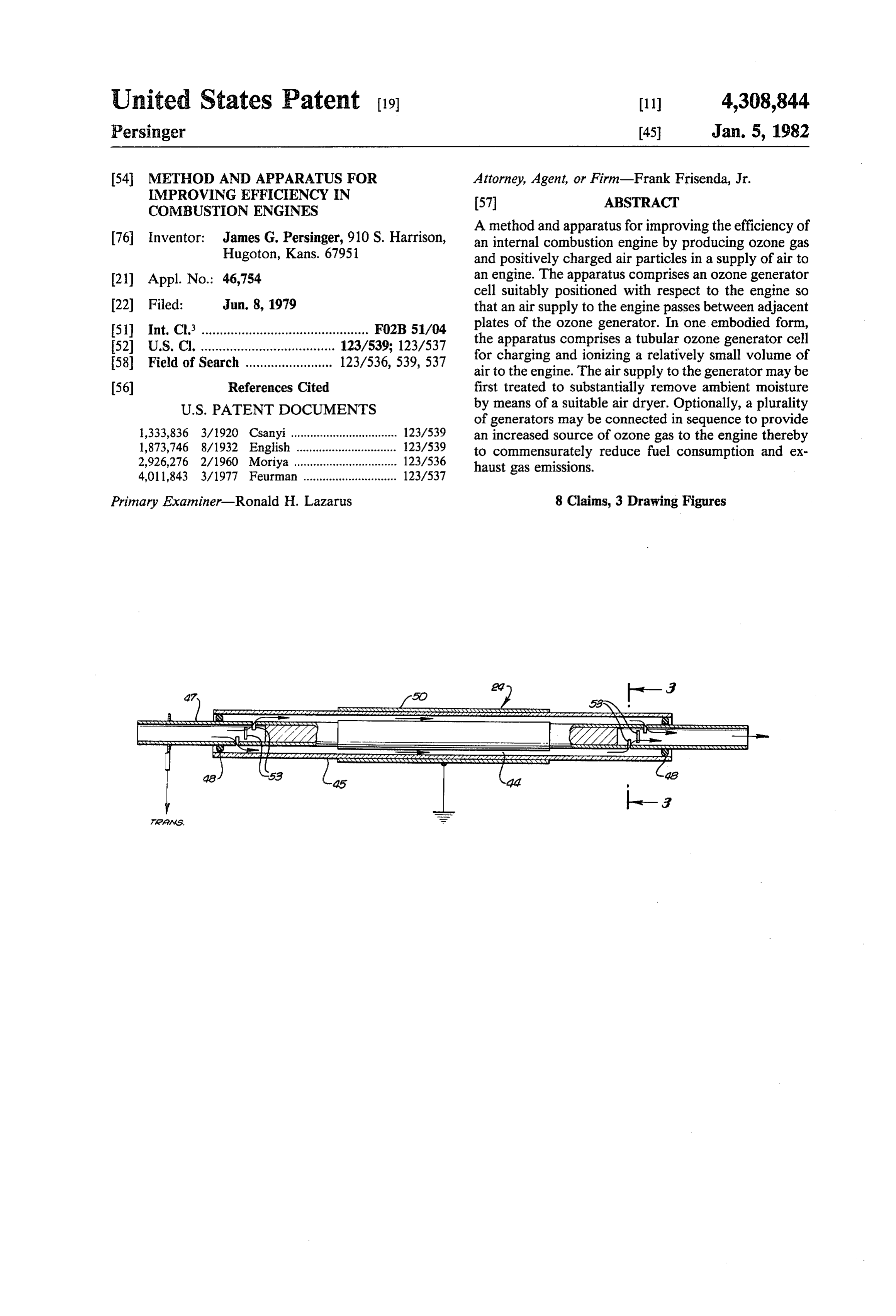
A method and apparatus for improving the efficiency of 76 Inventor: James G. Persinger, 910 S. Harrison, an internal combustion engine by producing ozone gas Hugoton, Kans, 67951 and positively charged air particles in a supply of air to 21) Appl. No.: 46,754 an engine. The apparatus comprises an ozone generator cell suitably positioned with respect to the engine so 22 Filed: Jun. 8, 1979 that an air supply to the engine passes between adjacent 51) Int. Cl. .............................................. FO2B 51/04 plates of the ozone generator. In one embodied form, 52 U.S.C. ..................................... 123/539; 123/537 the apparatus comprises a tubular ozone generator cell 58) Field of Search ........................ 123/536,539, 537 for charging and ionizing a relatively small volume of air to the engine. The air supply to the generator may be 56) References Cited first treated to substantially remove ambient moisture
of generators may be connected in sequence to provide 1,333,836 3/1920 Csanyi................................. 123/539 an increased source of ozone gas to the engine thereby 1,873,746 8/1932 English ... ... 123/539 to commensurately reduce fuel consumption and ex 2,926,276 2/1960 Moriya ................................ 123/536 haust gas emissions.
4,011,843 3/1977 Feurman ............................. 123/537
Primary Examiner-Ronald H. Lazarus 8 Claims, 3 Drawing Figures
C Syskawswaxxyyxxxxxx xxx xxxx
As s AAsse-N
AXXXYYYYYYAssaxww.vassassive Kawasawaxes & syrssexxs
42.4%a 2%azazza2a2azzarazzaar ZYZZazazaleazaayaaaaaaay
Page 2
Drawing sheet — no readable text.
Page 3
70,000 volts, or as low as 5,000 volts, the potential alter
METHOD AND APPARATUS FOR IMPROVING nating at a frequency in the range between about 200 EFFICIENCY IN COMBUSTION ENGINES and about 400 cycles per second. In one embodied form, the ozone generator includes ionizing cells comprised of
BACKGROUND OF THE INVENTION 5 a series of plates to which the resultant potential is ap This invention relates to a method and an apparatus plied and a dielectric material separating the charge for producing ozone gas and positively charged air plates. A supply of air is filtered and dried air, by suit particles in a supply of air to an engine, and to a method able means, flowed between gaps of the charged plates, of using such apparatus for improving the efficiency of O before being directed to a carburetor where resultant an internal combustion engine, both from the standpoint ozone gas and positively charged air are mixed with of reduced fuel consumption and reduced exhaust gas fuel. In one preferred embodiment of the invention, a emissions. plurality of ozone generators sequentially connected to The addition of ozone gas to a combustion mixture in each other may be utilized. In another preferred em an internal combustion engine is disclosed, for example, 15 bodiment a large ionizing cell capable of passing and in U.S. Pat. No. 1,982,484 issued to Runge. The Runge ionizing the maximum volume of air the engine may system utilizes a distributor of an internal combustion demand and a small cell which can produce the desired engine to produce ozone gas which is then added to the effect on a small volume of air is extremely effective. combustion mixture flowing through an intake manifold Accordingly, the ozone generator of the present in of the engine. The system is said to both prevent deposi vention ionizes oxygen in the air supply thereby pro tion of carbon in the engine's cylinders and to consume 20 ducing ozone and also applies a positive charge to the carbon already so deposited. U.S. Pat. No. 1,989,499 to air particles which promotes improved mixing and Sabot discloses a device which achieves better mixing burning of the fuel and which promotes more complete of a combustible fuel, such as heavy oil, and air used to combustion support combustion by using an ionizer which produces the engine. of the fuel in the combustion chambers of ozone and charges ions of the air-fuel combustion mix 25 ture. U.S. Pat. No. 2,410,403 to Baudine discloses a Other features and advantages of the present inven method for more rapid starting of aircraft engines in tion will become apparent from the following detailed cold ambient temperature by injecting ozone into com description, taken in conjunction with the accompany bustion air flowing into such engines. ing drawings, which will illustrate by way of example, A wide variety of apparatus for producing ozone gas 30 the principles of the invention.
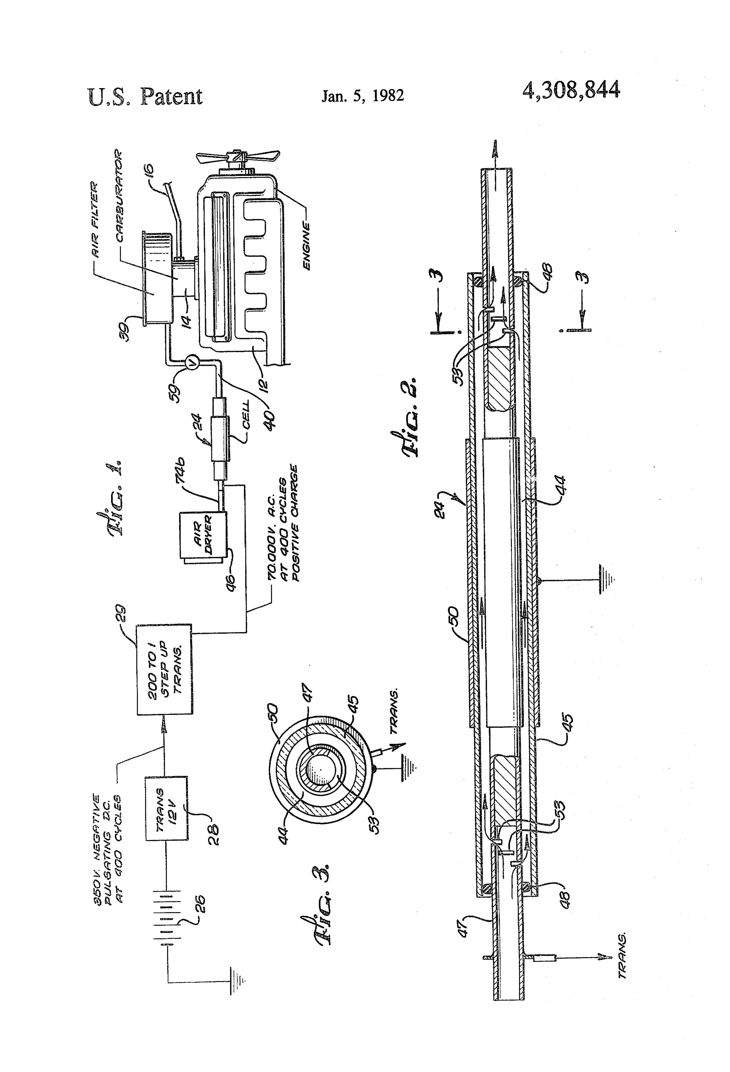
are also disclosed in the art. For example, U.S. Pat. No. DESCRIPTION OF THE DRAWINGS 4,051,043 to Harter discloses an apparatus which applies a large alternating potential to plates separated by a FIG. 1 is a schematic flow diagram of one embodied flow of air to produce ozone gas. The Harter apparatus form of the invention showing suitable circuitry and an uses a D.C. power source, transformer means and 35 ozone generator connected in sequence to an air intake switching means to produce a potential across the plates manifold of a standard automobile engine; in the range of 100 to 3,000 volts. Accordingly, the FIG. 2 is a longitudinal sectional view of an embod potential in such apparatus alternates at a frequency in ied ozone generator cell in accordance with the present the range of 3,000 to 4,000 cycles per second. invention;
While the foregoing devices may have accomplished FIG. 3 is a cross sectional view of the second embod intended objectives, the present invention is designed ied cell taken substantially along line 3-3 in FIG. 2 for improving efficiency of an internal combustion en gine during the normal course of its operation. In accor DESCRIPTION OF THE PREFERRED dance with the present invention, a novel apparatus and EMBODIMENTS method provides significant improvement in perfor 45 As shown in the drawings, and with reference to mance of the engine which justifies both cost of con FIG. 1, the present invention comprises an ozone gener struction and cost of upkeep. Moreover, the instant ator cell 24 which acts on an air supply to an internal device is reliable and will remain in service during the combustion engine 12. The generator cell 24 produces life of the engine which it supports and will remain in
Service without requiring frequent maintenance. Addi 50 ozone in the air supply and induces a positive charge on portions of such supply. A carburetor 14 atomizes a tionally, the cost of operation of the apparatus of the suitable supply of fuel, from a fuel line 16, and mixes the present invention is significantly less than the beneficial fuel together with the ozone gas and charged air supply increase in engine performance which it produces. and discharges this mixture into an intake manifold (not SUMMARY OF THE INVENTION 55 shown) of an internal combustion engine 10 for in The present invention significantly improves the effi stance, a standard automobile engine. The generator ciency of an internal combustion engine, reducing both cell 10 can also be used in conjunction with engines fuel consumption and exhaust pollutants by producing having fuel injection devices rather than carburetors ozone gas and positively charged particles in an air and in such applications the generator cell 24 processes supply which supports combustion in the engine. 60 the air supply before it enters the air intake manifold of In all embodied forms, the novel apparatus of the a spercharger.
present invention comprises a relatively compact, In one embodiment form, as best shown in FIG. 2, the ozone generator which may be powered, for example, generator cell 24 comprises metallic plates 47 and 50 by a standard 12 volt automobile battery. disposed adjacent to one another and separated from More specifically, the ozone generator is powered by 65 each other by a dielectric material 45 and an air gap 44. an electrical source, comprised of D.C. current stepped A potential is induced across adjacent plates 47 and 50 up by suitable transformers and switching means which causing ionization of oxygen in the air flowing through convert the input supply to a potential of as high as he gap 44 which results in production of ozone gas and
Page 4
ionizing air particles thus producing a gaseous mixture transformer 29 can produce an output of up to 70,000 having a positive charge. volts from the 350 volt input of the first transformer 28. In accordance with the present invention, illustrated The electrical output of the second transformer 29 is in FIG. 1, the generator cell 24 is suitably disposed adapted to alternate at the same frequency as the electri within the air supply to the engine 12 and thereby pro- 5 cal output from the first transformer 28. duces ozone within the air supply and induces a charge In accordance with the present invention, the cell 24 on the mixture by applying an alternating potential of is positioned directly in the input of an air filter 39 of the up to 70,000 volts across the plates 47 and 50. The po engine 12. Of course, any suitable configuration may be tential across the gap 44, alternating at a frequency in used and the cell 24 could be located at another conve the range between about 200 and about 400 cycles per 10 nient position which allows the gaseous output to be second, produces ozone gas and adds positive charges transmitted to the carburator engine 12 by a hose 40. to portions of the air supply thereby significantly im However, the hose 40 must be capable of carrying proving the mixing of the fuel and the air and also im ozone gas and charged air without excessive deteriora proving the dispersion of the fuel-air mixture in the tion. In this respect, PVC, neoprene or other inert mate combustion chambers (not shown) of the engine 12. 15 rial could be used.
In one embodiment as will be described more fully In a preferred embodiment of the invention, illus below, the apparatus of the present invention may com trated in FIGS. 2 and 3, a tubular ozone generator cell prise two cells sequentially connected to produce 24 is used to provide ozone and ionized air to the engine ozone. Accordingly, one cell 24 charges the air and 12. In the cell 24, two cylindrical metallic plates 47 and produces ozone and improves performance when the 20 50 are separated by a dielectric and an air gap 44 or engine is under light use and drawing only a small vol conduit. Accordingly, a borosilicate glass tube 45 acts ume of air for combustion. Additionally, the plurality of as a dielectric and also acts as a conduit to contain air as cells improves the performance of the engine 12 under it flows between the plates 47 and 45. A cylindrical heavier use and when the volume of air flowing into the conductive metal tube 47 is disposed within the glass engine 12 is greater. 25 cylinder 45 to function as the charged plate and means Referring to FIG. 1, the electrical power source for for directing air through the cell 24. The metal tube 47 the generator cells may comprise a standard recharge is sealed in position within the glass cylinder 45 by able twelve volt direct current battery 26 of the type suitable means such as air tight O-rings 48. Overlying usually associated with internal combustion engines the outside of the tube is the grounded plate 50 which in from which a current of between about five and six 30 this embodiment is a conductive metal foil wrapped amps is drawn. The current from the battery 26 is suit about the outside of the glass cylinder 45. ably fed to a first transformer 28 which converts the The metal tube 47 is blocked off at a location inside electrical output of the battery 26 to a negative 350 volt the glass cylinder 45 by a plug of sealant such as "Liq D.C. potential, pulsed at approximately 400 hertz. uid Steel" brand glue sold by Permatex Co. of Newing Switching means in the first transformer 28 convert the 35 ton, Conn. The blockage prevents air from passing the D.C. current output of the battery 26 into an alternating entire length of the metal tube 47. A suitable number of waveform ranging from about 0 volts to 350 volts at a slits or holes 53 are located in a circumferential portion given frequency per second, in one preferred embodi of the metal tube 47 so that air flowing with the metal ment of the invention. However, while the 350 volt tube 47 can escape from the tube 47 and pass into and potential alternates at approximately 400 cycles per 40 through the conduit 44 between the outside diameter of second, frequencies as low as 200 cycles per second the metal tube 47 and the inside diameter of the glass have been satisfactorily used. Preferably, the waveform cylinder 45. In this manner, air flowing within the metal of the electrical output of the fist transformer 28 is a tube 47, can detour around the blockage in the tube, and square wave. A suitable transformer 28 for use in con then enter the tube at a point past the blockage. In oper nection with the present invention is commercially 45 ation, air is provided to the cell 24 flowing through available from Firewell Products Corporation of metal tube 47, and escapes from the tube 47, through Northridge, California. For a further disclosure of the slits 53 and enters the conduit or air gap 44 between the Firewell device reference may be had to disclosure in metal tube 47 and the glass cylinder 45. Subsequently, U.S. Pat. No. 3,658,044, which is hereby incorporated the air flows through the gap between the plates 47 and by this reference. 50 45, is ionized producing ozone which re-enters the Variacs capable of adjusting the frequencies of alter metal tube 47 and leaves the cell 24. nation have been incorporated in some transformers, of In one presently preferred embodiment, a plurality of the type used in the invention, but such variacs are not cells 24 are installed and concurrently operated. One mandatory. Accordingly, a transformer with a fixed cell 24 may be inserted directly within the air supply to frequency output is also suitable. Empirical results have 55 the engine 12. The gaps 44 between the plates 47 and 50 shown that the instant apparatus will increase vehicle are sufficiently large that they can accommodate a nor gas mileage by 20% at a frequency of 200 cycles, and mal flow of air to the engine. However, it has been commensurately greater increase when the frequency is determined that when the volume of air required by the increased to a maximum of about 400 cycles. engine 12 is small, one cell 24 acting alone, provides With reference to FIG. 1, the output from the first 60 better fuel efficiency and pollutant reduction. Accord transformer 28 is suitably connected to a second trans ingly, by using the cell 24 when even the engine is oper former 29 whose step-up ratio is approximately 200:1. A ated at slower speeds or under lighter loads, significant high performance automobile ignition coil can be suit improvement in fuel performance can be achieved. ably used for the second transformer 29. Such a trans Moreover, the improvement in fuel performance pro former is commercially available from Automotive 65 duced by using the cell 24 also occurs in damp or wet Controls Corp. of Banford, Connecticut under the des weather conditions. The cell 24, with its air passage ignation "Super Coil," and under the trademark may be conveniently connected to the air filter 39 or air ACCEL Eliminator Ignition. Accordingly, The second intake of the engine to induce a flow of air through the
Page 5
cell 24, such as by a suitable pump. A hose 40 most Another significant advantage achieved by the pres suitably made of PVC, or other inert material, connects ent invention is the reduction in the amount of NO, CO, the cell 24 to the air-filter 39 or air intake manifold (not and unburned hydrocarbon emissions which are re shown) of the engine 12. A valve 59 is used to throttle leased from the engine exhaust by at least 7% with the the flow through the cell 24 at a rate of about 5 cubic 5 above listed amount of ozone addition. feet per minute. At this rate, the cell 24 will produce It has been found in the present invention that the use approximately 2 lbs of ozone per hour. of a high potential allows the production of the required In some instances, improvement in fuel efficiency and amount of ozone and the desired amount of the positive exhaust gas emissions results when air entering the cell ionization of the air which is sufficient to effect the 24 is dry. For this reason an air dryer 46 is provided increased efficiency of the engine.
before air is directed to the ozone generator cells. A While a particular form of the invention has been suitable dryer 46, which is capable of reducing the dew illustrated and described, it will be apparent that various point of the air to -100' F., is "J-150 filter, 'a dryer modifications can be made without departing from the separator commercially available from Fuel Incorpo spirit and scope of the invention.
rated, 1108 Industrial St., Hugoton, Kans. 15 I claim:
While location of the ozone generator cells of the 1. An apparatus for improving efficiency of a com present invention is not of critical importance, a typi bustion engine by ionization of an air supply to the cally mounting will be described below, with reference engine, the apparatus comprising:
to FIG. 1. The cell may be placed immediately adjacent inlet means for receiving the air supply to the com the air filter 39. The opening of the air filter 39 is modi 20 bustion engine;
fied slightly so that a cell can be placed in the intake of means for ionizing the air supply to produce ozone the air filter 39. The cell 24, suitably mounted, is con gas and to produce a positively charged air and nected to the dryer 46 by its own intake hose 74b. The ozone gas mixture in an amount effective to im first transformer 28 and second 29 transformers can be prove engine efficiency;
attached to the rigid sheet metal near the engine 12 such 25 said means for ionizing the air supply comprising in as the inside on the front wheel well or the battery combination: a first inner cylinder composed of an holder (not shown). electrically conductive material, a second interme Accordingly, the present invention provides an appa diate cylinder composed of a dielectric material, ratus for improving efficiency of a combustion engine and a third outer cylinder composed of an electri by ionization of an air supply to the engine. The unique 30 cally conductive material, each cylinder being lon apparatus comprises: inlet means for receiving the air gitudinally aligned with one another in a concen supply to the combustion engine; means for ionizing the tric arrangement and to provide a cylindrical gap air supply to produce ozone gas and to produce a posi for directing the flow of air supply between an tively charged air and ozone gas mixture in an amount exterior surface of said first inner cylinder and an effective to improve engine efficiency. 35 interior surface of said second intermediate cylin The means for ionizing the air supply comprises in der;
combination: a first inner cylinder composed of an elec means for directing the flow of air supply received in trically conductive material, a second intermediate cyl an interior portion of one end of said first inner inder composed of a dielectric material, and a third cylinder to said cylindrical gap where ionization of outer cylinder composed of an electrically conductive 40 the air supply is effected and subsequently for di material, each cylinder being longitudinally aligned recting the gaseous ionized mixture back to the with one another in a concentric arrangement and to interior portion of an opposite end of said first inner provide a cylindrical gap for directing the flow of air cylinder; and supply between an exterior surface of the first inner outlet means for directing the resultant gaseous ion cylinder and an interior surface of the second intermedi 45 ized mixture to said combustion engine. ate cylinder. 2. The apparatus as defined in claim 1 wherein said The inventive apparatus further includes means for means for ionizing the air supply further comprises: directing the flow of air supply received in an interior means for providing an electrical potential alternating portion of one end of the first inner cylinder to the between a prescribed maximum value and a mini cylindrical gap where ionization of the air supply is 50 mum value.
effected and subsequently for directing the gaseous 3. The apparatus as defined in claim 2, wherein said ionized mixture back to the interior portion of an oppo means for providing an electrical potential comprises: site end of the first inner cylinder. Additionally, outlet battery means; and means for directing the resultant gaseous ionized mix transformer means for converting the output of said ture to the combustion engine is included. 55 battery means to alternating electrical potential, While the foregoing description describes modifica between about 5,000 volts and about 70,000 volts at tions of a standard automobile engine, those skilled in a frequency in the range of about 200 to about 400 the art will appreciate that any internal combustion cycles per second.
engine can be utilized in accordance with the present 4. The apparatus as defined in claim 1 wherein said invention. For instance, the present system may be uti 60 second intermediate cylinder of dielectric material com lized with any internal combustion engine, stationary prises boro-silicate glass.
engines, irrigation pump engines, or the like, powered 5. The apparatus as defined in claim 1, wherein said by a fossil or hydrocarbon fuel such as natural gas, third outer cylinder comprises an electrically conduc liquified petroleum, gasoline, diesel or mixtures thereof. tive metal foil wrapped about a portion of the exterior It has been determined that fuel efficiency (miles/gal 65 of said second intermediate cylinder composed of a ions) will be increased from 7 percent to 50 percent dielectric material.
with an added amount of ozone from 1 to 6 lb. per 100 6. The appartus as defined in claim 1, wherein said horse power hour. means for directing the flow of air supply comprises a
Page 6
plurality of holes provided in circumferential end por- means for ionizing the air supply to produce ozone gas tions of said first inner cylinder. and to produce a positively charged air and ozone gas 7. The apparatus as defined in claim 1, wherein said mixture in an amount effective to improve engine effi means for ionizing the air supply produces from about 1 ciency comprises a plurality of means for ionizing the to about 6 lbs. per horse power hour of ozone gas. 5 air supply sequentially connected with one another. 8. The apparatus as defined in claim 1, wherein said is sk

Provenance
- Collection
- Cited prior art
- Original PDF
- patentimages.storage.googleapis.com →
- Filed
- 1979-06-08
- Pages
- 6
- Method
- pdftotext (the PDF's own text layer) + pdftoppm 300dpi page scans
- Source
- Google Patents bibliographic record
- Granted
- 1982-01-05
- Inventors
- James G. Persinger
- Transcribed from
- patentimages.storage.googleapis.com →