patent · US5809768
Hydrogen-oxygen combustion turbine plant
22 September 1998
Page 1 — bibliographic record
United States Patent (19) 11 Patent Number: 5,809,768 Uematsu et al. (45) Date of Patent: Sep. 22, 1998 54 HYDROGEN-OXYGEN COMBUSTION 5,644,911 7/1997 Huber ..................................... 60/39.05 TURBINE PLANT 5,687,559 11/1997 Sato ..................................... 60/39.182
(75) Inventors: Kazuo Uematsu, Hidetaka Mori; Primary Examiner Louis J. Casaregola Hideaki Sugishita, all of Takasago, Attorney, Agent, or Firm Wenderoth, Lind & Ponack, Japan LLP.
Assignee: Mitsubishi Heavy Industries, Ltd., 57 ABSTRACT Tokyo, Japan A hydrogen-oxygen combustion turbine plant having an improved thermal efficiency and capable of being designed
Appl. No.: 833,690 in a flexible manner. The plant is constructed as follows. A Filed: Apr. 8, 1997 compressor is divided into a plurality of units (1A and 1B), a water injection device (14) is disposed between the com
Int. Cl." ................................................. F03C 3/22 pressor units, and exhaust water from a condenser (10) of a U.S. Cl. ...................... 60/39.465; 60/39.52; 60/39.53 Second turbine (6) is utilized as a water Supply. A gas turbine Field of Search .............................. 60/39.161, 39.17, is also divided into a plurality of units (3A to 3C) with 60/39.182, 39.465, 39.52, 39.53, 39.55, multiple axes. Further, not only extracted steam (9A and 9B) 728 from the compressors (1A and 1B) but also the extracted steam (12A and 12B) from the second turbine (6) and the
References Cited extracted steam (13A and 13B) from the exhaust of the third turbine (8) are used as cooled Steam for gas turbines (3A to
4,148,185 4/1979 Somers ................................... 60/39.17 5,331,806 7/1994 Warkentin ............................ 60/39.465 4 Claims, 3 Drawing Sheets
Page 2
Drawing sheet — no readable text.
Page 3
Drawing sheet — no readable text.
Page 4
Drawing sheet — no readable text.
Page 5
HYDROGEN-OXYGEN COMBUSTION into a plurality of units, a water injection device having the TURBINE PLANT condensate of the Second turbine as its water Supply is provided between the divided compressors, and the axes of
FIELD OF THE INVENTION rotation of the divided gas turbines differ from each other.
The present invention relates to improvements in a 2) In addition to the structure of Item 1, Steam extracted hydrogen-oxygen combustion turbine plant and to a cooled from the compressor and/or Second turbine is used as the Steam extraction Structure in a hydrogen-oxygen combustion cooled Steam for the gas turbine.
gas turbine. 3) In addition to the structure of Item 1, steam extracted from the third turbine is used as the cooled Steam for the gas
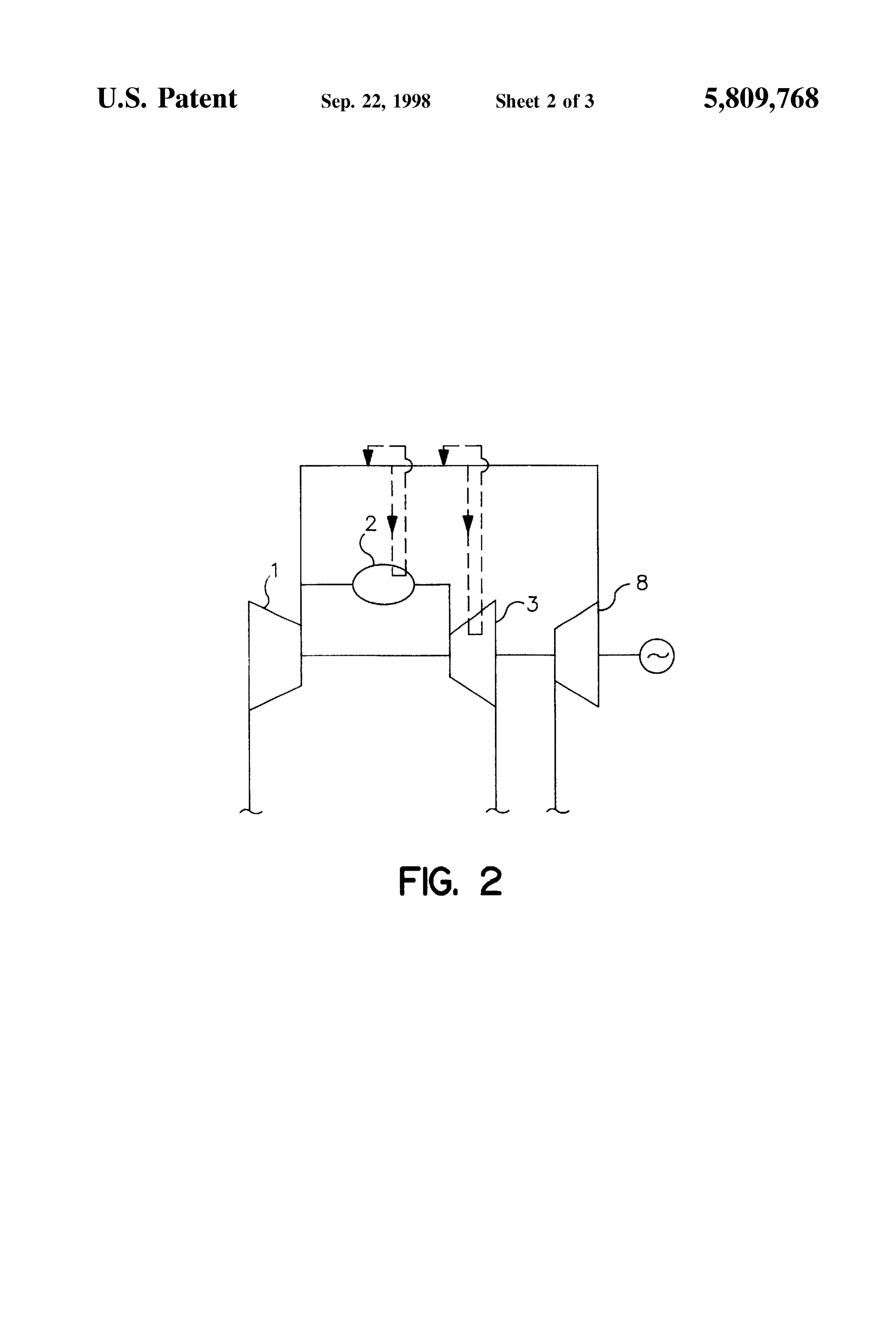
FIG. 3 is a Schematic diagram showing an example of a 4) In addition to the structure of Item 1, Steam extracted conventional hydrogen-oxygen combustion turbine plant. from the third turbine is used as recovery-type cooled Steam Hydrogen, oxygen and gas turbine exhaust Steam com for the turbines and/or the combustion chamber. pressed by a compressor (1) is Supplied to and mixed in a 15 In the means described in Item 1, where the pressure ratio combustion chamber (2). The Supplied Steam is then com is high, Since the number of revolutions can be optimally busted to make high-temperature combustion Steam for Selected by making the compressor a divided type and driving a gas turbine (3). After this exhaust Steam is Sub allowing the divided gas turbine units to have a number of jected to heat recovery by heat exchangers (4) and (5) on the axes (i.e. dividing the gas turbine into a plurality of units downstream side of the gas turbine (3), it is fed back to the with different axes of rotation) so that not only the efficiency compressor (1). Also, part of the exhaust Steam is extracted can be improved but also, the problems of avoiding the from a communicating pipe between the heat exchangers (4) Surging of the compressor and axial vibration of the turbines and (5) to drive a second turbine (6). The exhaust of this and the control of the lowering performance (generation of second turbine (6) is condensed by a condenser (10), heated Shock waves) caused by the peripheral Speed of the impel by a heat exchanger (7) provided in the pipe line, heated 25 lers and the flow Speed of the Steam can be Solved with ease. again by the heat exchangers (5) and (4) to become low Also in the means described in Item 1, Since a water temperature, low-pressure Steam, and after driving a third injection device is provided between the divided turbine (8), returns to the inlet side of the combustion compressors, the Steam whose temperature has been reduced chamber (2). Reference numeral (11) indicates a feed water by compression can be effectively cooled, the temperature at booster pump. which it flows into the compressor at the next Stage can be The cooled steam and seal steam for the turbine blades reduced, and the Structural design can be improved. Also, and discs of the gas turbine (3) are extracted from the Since the condensate of the Second turbine is used as the compressor (1) by a cooled steam pipe (9) and supplied to water Supply thereof, loSS can be kept to a minimum and the the gas turbine (3). labor and cost involved in preparing a Special water Supply 35 can be Saved.
The cycle of the conventional hydrogen-oxygen combus Since the steam extracted from the second turbine in the tion turbine plant described above is strictly conceptual, and where the preSSure ratio of the compressor is high, Such above Item 2, and the exhaust of the third turbine in the cycle cannot be realized with a single compressor from the above Item 3, are utilized as the cooled Steam for the gas Structural point of View. This problem also applies to gas 40 turbine, fine temperature and pressure cooled Steam can be turbines. Supplied. Also, Since the Steam from the Second and third Also, utilization of the compressed Steam from the com turbines is Steam whose work has already been finished in preSSor as the cooled Steam and Seal Steam for the turbine is concerned.it has great advantages as far as the efficiency the turbines, blades and discs, as in the case of a conventional gas turbine leads to the use of high-energy compressed Steam for 45 In addition, where the cooled Steam is exhausted into the cooling and Sealing, which results in a great loSS. main flow, a large amount is lost, but in Item 4, Since the steam extracted from the exhaust of the third turbine is
SUMMARY OF THE INVENTION recovered after cooling the gas turbine and/or the combus tion chamber and not exhausted into the main flow, effi
The inventors of the present invention, in order to solve ciency is improved.
the problem involved in conventional gas turbine, have 50 provided the hydrogen-oxygen combustion turbine plant BRIEF DESCRIPTION OF THE DRAWINGS described in the following items 1 through 4. These and other features, aspects and advantages of the 1) A hydrogen-oxygen combustion turbine plant compris present ing a compressor, a gas turbine device including a hydrogen ence to invention will become better understood with refer the following description, appended claims and oxygen combustion chamber and a gas turbine, a first heat 55 accompanying drawings, wherein:
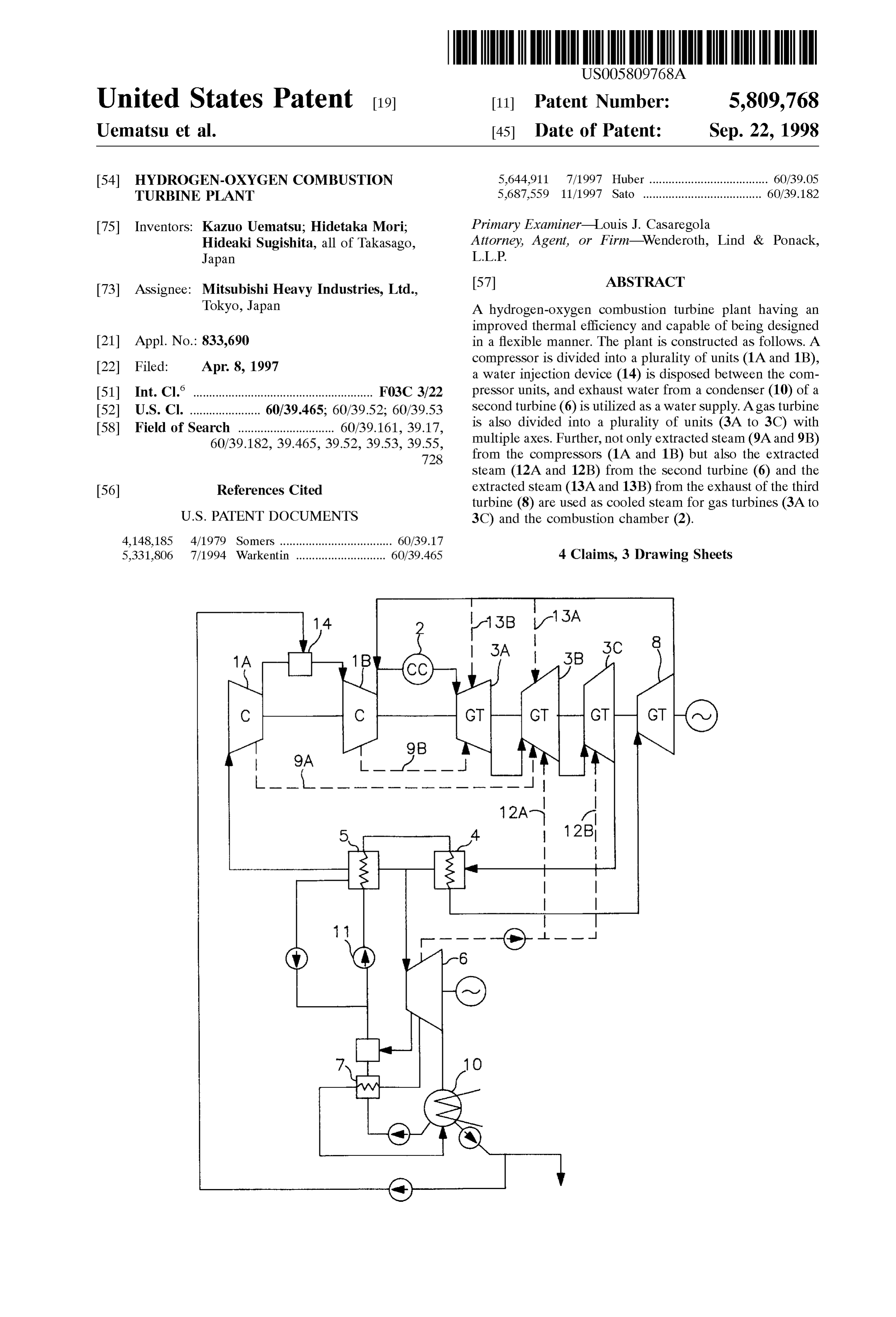
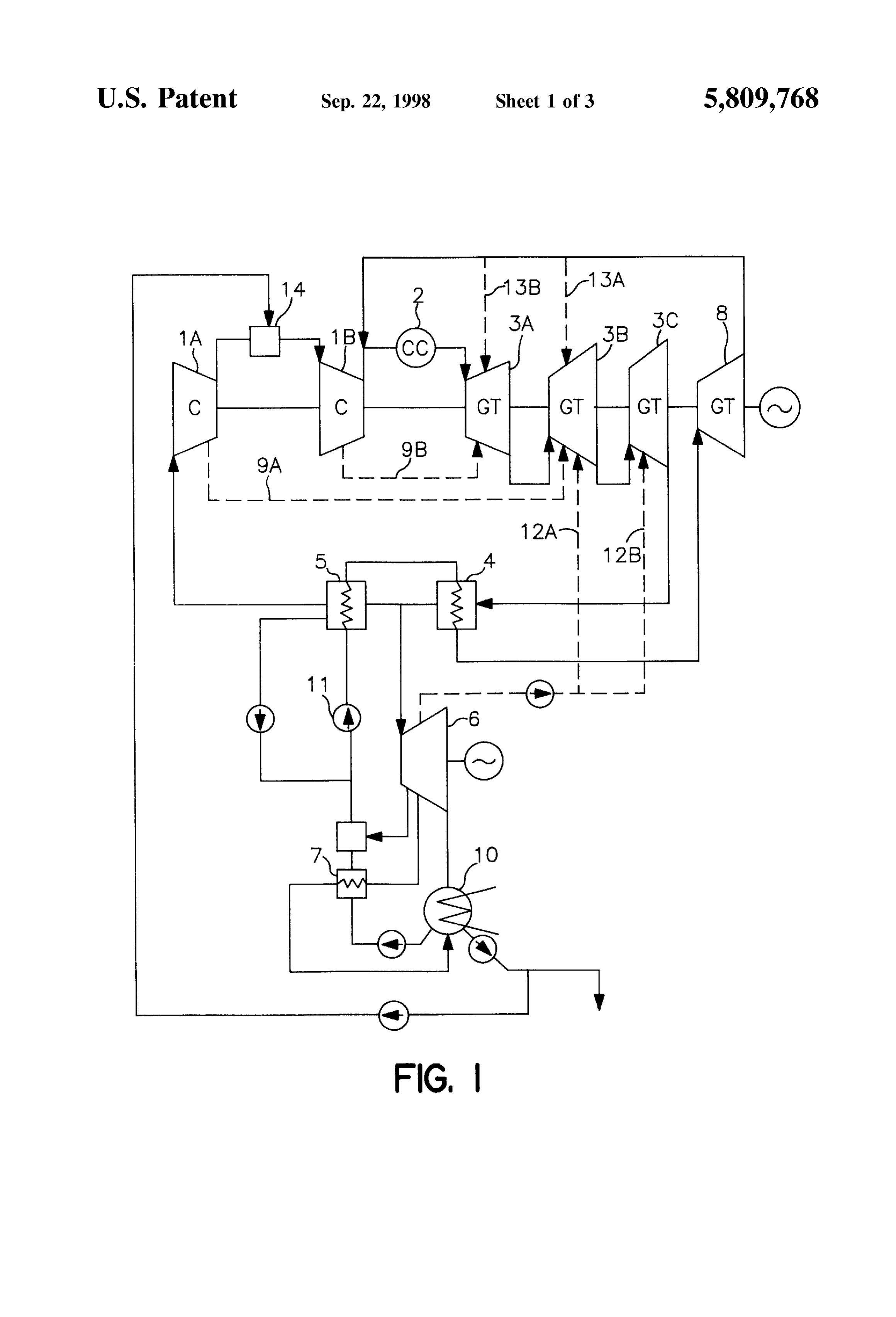
eXchanger for recovering heat from the exhaust of the gas turbine, a Second heat eXchanger for further recovering heat FIG. 1 is a Schematic diagram illustrating a first embodi from part of the gas turbine exhaust exiting the first heat ment of the present invention;
eXchanger, a pipe line for returning the gas turbine exhaust FIG. 2 is a Schematic diagram illustrating a Second exiting the Second heat eXchanger to an inlet of the 60 embodiment of the present invention; and compressor, a Second turbine driven by the remainder of the FIG. 3 is a Schematic diagram illustrating an example of gas turbine exhaust exiting the first heat eXchanger, and a a conventional hydrogen-oxygen combustion turbine plant. third turbine driven by steam obtained by sequentially DETAILED DESCRIPTION OF THE heating, by means of the Second and first heat eXchangers, a INVENTION condensate from the Second turbine and whose exhaust is 65 returned to the hydrogen-oxygen combustion chamber, In FIG. 1, in order to avoid repetition concerning those wherein the compressor and gas turbine are each divided portions that are the same as those in the prior art described
Page 6
with regard to the above FIG. 3, the same reference numerals What is claimed is:
will be used and detailed explanation thereof will be omit 1. A hydrogen-oxygen combustion turbine plant compris ted. ing a compressor, a gas turbine device including a hydrogen In the present embodiment, the compressor is divided into oxygen combustion chamber and a gas turbine, a first heat a plurality of compressor units (1A) and (1B), with a water eXchanger for recovering heat from exhaust of the gas injection device (14) disposed between these compressor turbine, a Second heat eXchanger for further recovering heat units (1A) and (1B). As the water supply of this water from part of gas turbine exhaust exiting the first heat injection device (14), the water exhausted from a condenser (10) of a second turbine (6) is utilized, so that loss is kept toeXchanger, a pipe line for returning gas turbine exhaust a minimum. Also, the gas turbine is constructed as multi exiting the Second heat eXchanger to an inlet of the axial gas turbines (3A), (3B) and (3C). compressor, a Second turbine driven by the remainder of the AS well as the cooled Steam of the blades and discS etc. gas turbine exhaust exiting the first heat eXchanger, and a of the gas turbines (3A), (3B) and (3C) being Supplied by third turbine driven by steam obtained by sequentially cooled steam pipes (9A) and (9B) from the compressors heating, by means of the Second and first heat eXchangers, a (1A) and (1B), extracted steam from the second turbine (6) 15 condensate from the Second turbine and whose exhaust is is Supplied by the cooled Steam pipes (12A) and (12B). returned to the hydrogen-oxygen combustion chamber, Further, extracted steam from the exhaust of the third turbine wherein the compressor and gas turbine are each divided (8) is supplied by cooled steam pipes (13A) and (13B). into a plurality units, a water injection device having the FIG. 2 illustrates a second embodiment of the present condensate of the Second turbine as its water Supply is invention, and is a Schematic diagram showing a case where cooled Steam is recovered. In this diagram, the same refer provided between the divided compressor units, and the ence numerals are used for those portions described above divided gas turbine units have different axes of rotation, and detailed explanation thereof are omitted. respectively.
In the present embodiment, the cooled Steam of the gas 2. The hydrogen-oxygen combustion turbine plant of turbine (3) and the combustion chamber (2) is extracted 25 claim 1, wherein Steam extracted from the compressor from a line which recovers the exhaust of the third turbine and/or Second turbine is used for cooling the gas turbine. (8) for the combustion chamber (2) and used, and each 3. The hydrogen-oxygen combustion turbine plant of portion of cooled Steam, after cooling the blades of the gas claim 1, wherein steam extracted from the third turbine is turbine (3) and the transition pipe etc. of the combustion used for cooling the gas turbine.
chamber (2), is returned to the line and recovered. 4. The hydrogen-oxygen combustion turbine plant of According to the present invention, not only is the heat claim 1, wherein steam extracted from the third turbine is loSS of a hydrogen-oxygen combustion turbine plant reduced used as recovery-type cooled Steam for cooling the turbine and efficiency improved, but also a minute structural design is made possible to hereby easily prevent the generation of and/or the combustion chamber.
compressor Surging, axial turbine vibration, shock waves, etc.
Provenance
- Collection
- Cited prior art
- Original PDF
- patentimages.storage.googleapis.com →
- Filed
- 1997-04-08
- Pages
- 6
- Method
- pdftotext (the PDF's own text layer) + pdftoppm 300dpi page scans
- Source
- Google Patents bibliographic record
- Granted
- 1998-09-22
- Inventors
- Kazuo Uematsu; Hidetaka Mori; Hideaki Sugishita; Mitsubishi Heavy Industries Ltd
- Transcribed from
- patentimages.storage.googleapis.com →