patent · US3946711
Hydrogen fired ignition system for internal combustion engines
30 March 1976
Page 1 — bibliographic record
United States Patent (19) 11 3,946,711 Wigal (45) Mar. 30, 1976 54 HYDROGEN FIRED IGNITION SYSTEM 3,710,764 111973 Jozlin........................ . . . . . 123/DIG. 9. FOR INTERNAL COMBUSTION ENGINES 3,853,097 12/1974 Kume............................. 123/DIG. 9 (76) Inventor: Voorhis F. Wigal, 909 Highland FOREIGN PATENTS OR APPLICATIONS Ave., Jackson, Tenn. 38301 226,766 8/1923 United Kingdom............. 123/143 B
22 Filed: Apr. 8, 1974 869,297 1/1942 France ............................ 123/143 B
Primary Examiner-Charles J. Myhre 52 U.S. Cl....... 123/119 E; 123/32 SP; 123/143 B; Assistant Examiner-Paul Devinsky 123/144; 123/DIG. 9 Attorney, Agent, or Firm-Browdy & Neimark (5) Int. Cl.’.......................................... F02B33/00 (58) Field of Search....... 123/142 B, DIG. 9, 119 E, 57) ABSTRACT 123/139 AD, 32 SP, 144 An ignition system for internal combustion engines comprises a spark plug located remote from the com 56) References Cited bustion chamber, a metering pump which supplies a UNITED STATES PATENTS mixture of hydrogen and oxygen gases to the remote 1,700,603 1/1929 Vreeland et al................. 123/143 B spark plug and a capillary-like tube for projecting an 1,957,541 5/1934 Johnson........................... 123/32 SP explosive flame front, created by the ignition of the 2,019,650 1 1/1935 Bischof............................ 123/139 E hydrogen and oxygen gases, into the combustion 2,396,602 3/1946 Posch.................................. 123/139 chamber to ignite a vaporized fuel-air mixture. 3,31 1,097 3/1967 Mittelstaedt.................... 12311 19 E 3,459,953 8/1969 Hughes et al................... 12311 19 E 6 Claims, 9 Drawing Figures
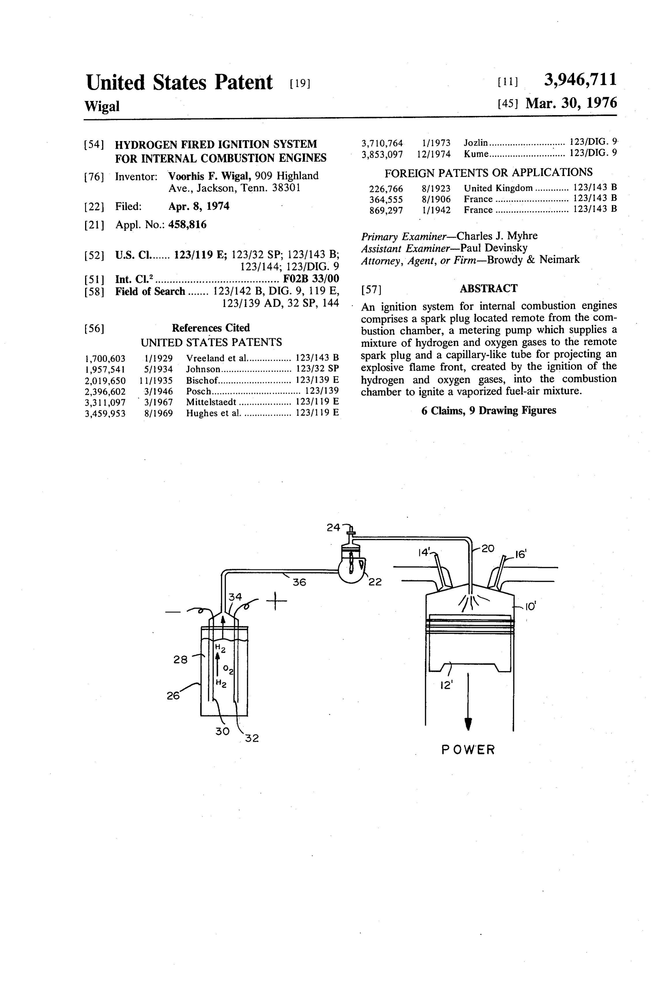
POWER
Page 2
Drawing sheet — no readable text.
Page 3
Drawing sheet — no readable text.
Page 4
resulting in an increase in efficiency and a decrease in
HYDROGEN FERED IGNITION SYSTEM FOR the emission of polluting gases. INTERNAL COMBUSTION ENGINES A further object is to provide a firing system for internal combustion engines which avoids any redesign
FIELD OF THE INVENTION of the engine itself and accomplishes the desired results The present invention relates to a hydrogen fired by relatively simple replacements which do not necessi ignition system for firing the combustible charge in tate mechanical changes other than the readjustment of conventional internal combustion engines and, more the fuel-air ratio, in the combustion chamber or in the particularly, such engines which use petroleum prod carburetor system.
ucts (or other liquid fuels) which form explosive mix 10 Yet another object of the present invention is to tures when vaporized in air. avoid the use of exotic fuels that would not be readily available and those that would be difficult or hazardous
BACKGROUND OF THE INVENTION to handle.
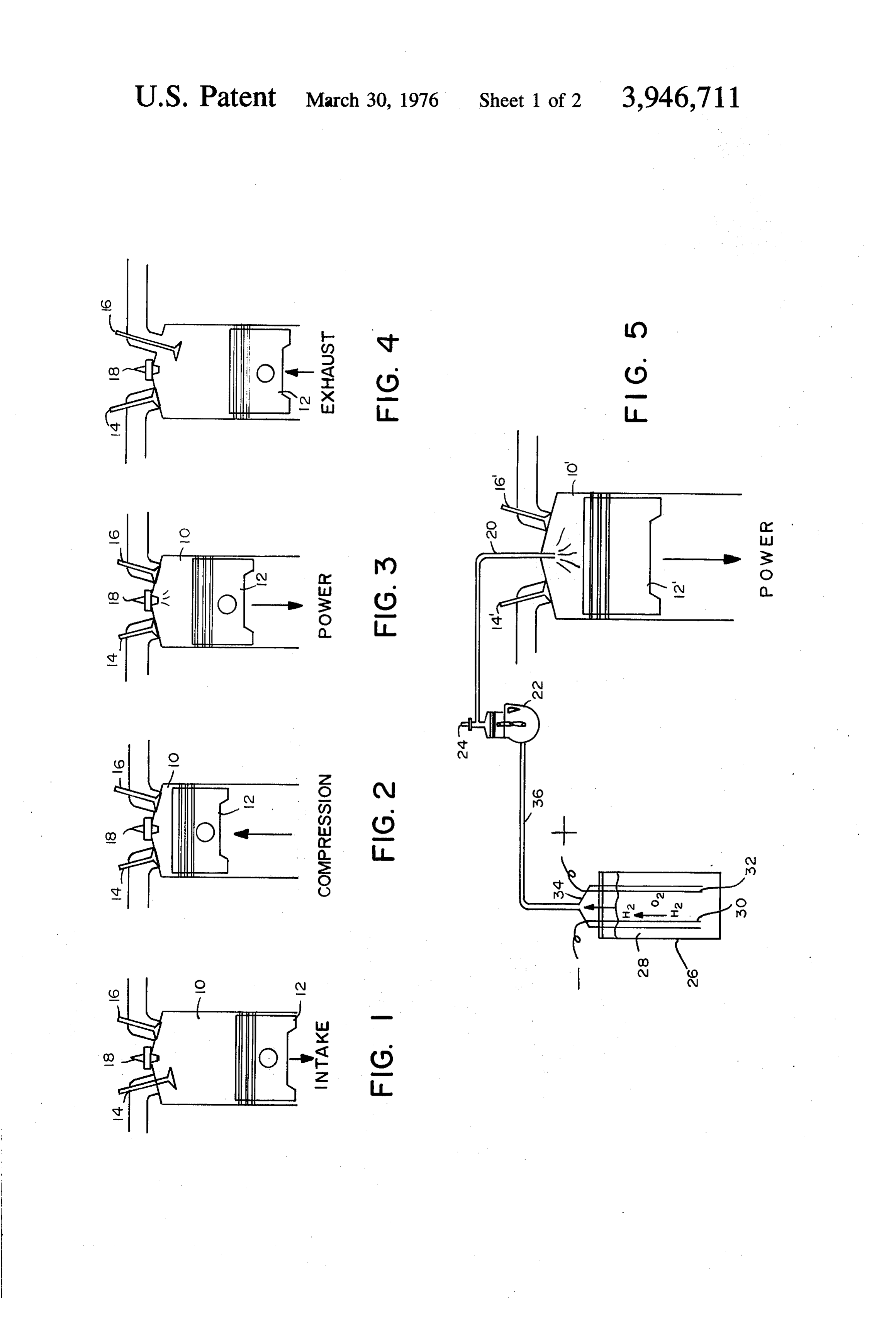
Referring now to FIGS. 1 through 4, there is shown In furtherance of these and other objects, a principal the normal sequence of operation for a typical 4-cycle 15 feature of the instant invention is an ignition system for internal combustion engine. On the intake stroke (FIG. internal combustion engines in which hydrogen and 1), an explosive mixture of vaporized fuel, such as oxygen are used in minute quantities, not as prime fuel, gasoline, and air is drawn into the cylinder 10 through but in a catalytic reaction for amplifying the relatively the open intake valve 14 as the piston 12 moves down 20 small spark from the igniter into a flame front of such ward. On the compression stroke (FIG. 2), the intake magnitude that it fires the conventional fuel-air mixture valve 4 is closed and the piston 12 rises to compress the in the main combustion chamber. Another feature is fuel-air mixture. On the power stroke (FIG. 3), the that the quantities of hydrogen and oxygen required are compressed fuel-air mixture is fired or ignited by an of such low order that they can be supplied from a electric arc across the gap of a spark plug 18, thereby 25 small and easily carried electrolytic generator or other propelling the piston 12 downward. On the exhaust type hydrogen generator, at the rate of demand, so that stroke (FIG. 4), the piston 12 travels upward expelling large reservoirs or high pressure storage tanks are not the burned gases through the open exhaust valve 16. required. Yet another feature is the absence of nitrogen After the burned gases have been expelled and the bearing air mixed with hydrocarbon fuel vapor in the exhaust valve 16 closes, the piston 12 moves downward 30 area of the arc of the igniter at the moment of firing. and the cycle is repeated. The hydrogen fired ignition system of the instant A major disadvantage of such conventional internal invention is characterized by an ignitor or sparking combustion engines is the inability of the electric spark means located remote from the combustion chamber, a to generate an instant flame front with sufficient magni metering pump which supplies a mixture of hydrogen tude to provide efficient combustion of the fuel-air 35 and oxygen to the remote igniter and a capillary tube mixture. This incomplete combustion is characterized for projecting an explosive flame front, created by the by a high percentage of unburned hydrocarbons result ignition of the hydrogen and oxygen gases, into the ing in wasted fuels and polluting gases which are dis combustion chamber to ignite the vaporized fuel-air charged into the atmosphere. mixture therein. The hydrogen and oxygen may be Heretofore, prior art devices have attempted to elim 40 supplied by a simple electrolytic cell which is con inate these disadvantages by utilizing auxiliary or pre nected to the metering pump.
combustion chambers. The prior art pre-combustion For a better understanding of the invention, a possi chambers, such as described in U.S. Pat. No. ble embodiment thereof will now be described with 3,066,661, function to ignite a fuel-air mixture which reference to the attached drawing, it being understood has a concentration that may be different from the 45 that this embodiment is intended to be merely exem fuel-air mixture in the main combustion chamber. plary and in no way limitative. These prior art pre-combustion chambers suffer due BRIEF DESCRIPTION OF THE DRAWING to the following disadvantages. Firstly, such pre-com bustion chambers must be of a sufficient size to hold FIG. 1 is a diagram illustrating the intake stroke of a the relatively large volume of fuel and air required to 50 typical 4-cycle internal combustion engine. create a flame front of sufficient magnitude to cause FIG. 2 is a diagram illustrating the compression complete combustion of the fuel-air mixture in the stroke of a typical 4-cycle internal combustion engine. main chamber. Secondly, such large volume pre-com FIG. 3 is a diagram illustrating the power stroke of a bustion chambers make complete purging after firing typical 4-cycle internal combustion engine. difficult. 55 FIG. 4 is a diagram illustrating the exhaust stroke of a typical 4-cycle internal combution engine.
SUMMARY OF THE INVENTION FIG. 5 is a schematic diagram of one embodiment of A principal object of the present invention is to over the hydrogen fired ignition system of the instant inven come the defects of the prior art, such as indicated tion as applied to a single piston cylinder in an internal above. 60 combustion engine.
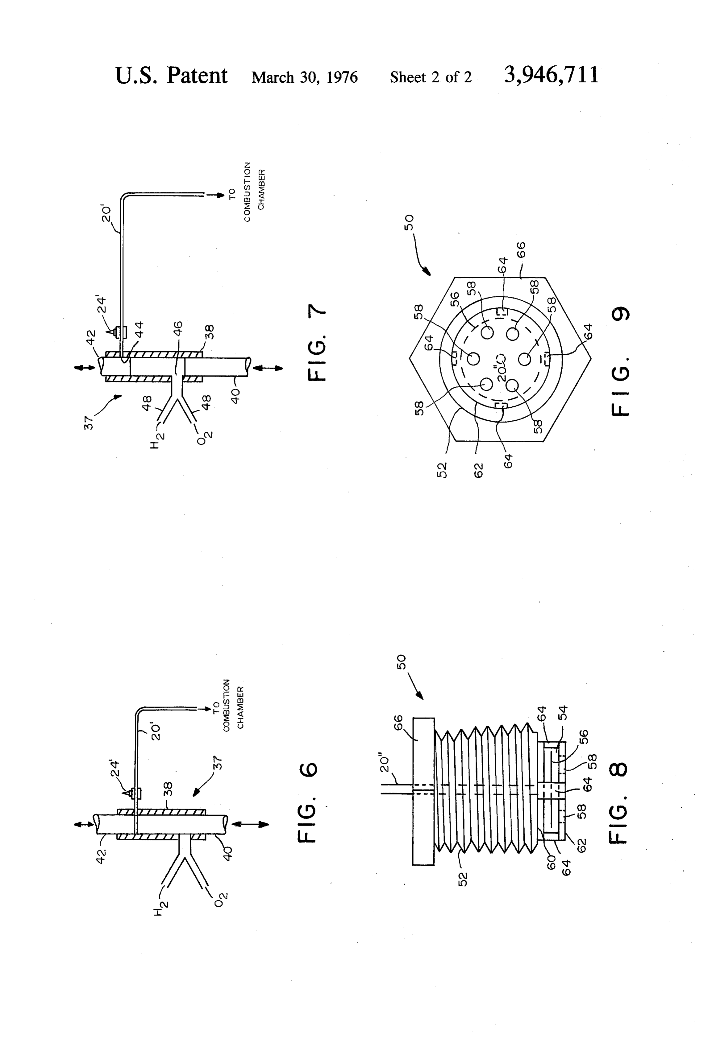
Another object of the present invention is to provide FIG. 6 is a schematic diagram of one possible em an improved firing system for internal combustion en bodiment of a metering pump at the instant of firing. gines. FIG. 7 is a diagram of the metering pump of FIG. 6 Another object is to provide a hydrogen fired ignition after firing.
system for firing the fuel-air mixture in internal com 65 FIG. 8 is an elevational view of one possible embodi bustion engines which greatly magnifies the initial ment of a valve which connects the capillary or firing flame front in the combustion chamber and permits tube to the combustion chamber.
utilization of a relatively lean fuel-air mixture, thereby FIG. 9 is a bottom view of the valve shown in FIG. 8
Page 5
DETAILED DESCRIPTION therefore, is of sufficient intensity to cause ignition and more efficient combustion of a fuel-air mixture that
Referring now to FIG. 5, the igniting spark plug 24 is otherwise might be too lean to ignite with the spark completely removed from the combustion chamber of alone.
the piston cylinder 10'. In its place is a relatively small 5 Although the use of undiluted hydrogen and oxygen capillary-like tube 20. A metered mixture of hydrogen gases is preferred, an effective firing charge can still be and oxygen gases is delivered through tube 20 to the produced even after one volume of hydrogen is diluted combustion chamber by a small pump 22 at a pressure with up to three volumes of air. This allows use of even that is higher than that of the vaporized fuel-air mixture a smaller electrolytic cell with proportionately less in the cylinder 10' when the piston 12 is at the top of 10 electric power needed for generating the hydrogen and the compression stroke. The metering pump 22, a pos Oxygen gases.
sible embodiment thereof being described in detail Referring now to FIGS. 6 and 7, there is shown one hereinafter, also acts as a shut-off valve to prevent the possible embodiment of a pump 37 that works well for backfiring of the hydrogen-oxygen charge into the feed low volume requirements. Sleeve-type pump cylinder line 36. Moreover, the pump is timed (by a linkage 5 38 houses two small reciprocating pistons 40, 42. Pis mechanism connected to the existing cam shaft or ton 40, having a relatively long stroke, is mechanically other synchronized member) to deliver the hydrogen synchronized with the engine crank (not shown) to oxygen mixture at the highest pressure just prior to the arrive at the top of the stroke and delivering the highest firing of spark plug 24. pressure at the instant of firing (see FIG. 6). Piston 42, By employing a capillary-like tube having a small 20 having a much shorter stroke, may also be synchro inner diameter, rather than a conventional pre-com nized. However, it has been found that it supplies the bustion chamber, a low volume of the hydrogen-oxygen necessary compression only when spring loaded. mixture may be easily maintained. Also, the capillary After firing by spark plug 24", pistons 40 and 42 like tube is more easily and completely purged by the move downward until piston 42 closes off port 44, metering pump after each firing. 25 which forms the entrance to the firing tube 20'. Stops A capillary or firing tube 5 inches long and having an (not shown) limit the vertical travel of piston 42 in such inner diameter of 0.03 inches and a total volume of a manner that it will just clear port 44 in the up position 0.005 cubic inches has been found to work satisfacto (see FIG. 6) and close it off completely when in the rily. Because a relatively small tube may be used with down position (see FIG. 7). As piston 40 moves down effective results, the volume of the hydrogen-oxygen 30 ward, a vacuum is created in the pump cylinder 38. mixture is quite small in relation to the fuel-air mixture Thus, when piston 40 clears port 46 in pump cylinder it fires. Therefore, in the present embodiment, only the 38 (see FIG. 7), the hydrogen-oxygen mixture is drawn hydrogen and oxygen gases surround the spark gap at therein. As piston 40 rises, the hydrogen-oxygen mix ignition. At the moment of detonation they recombine ture is compressed between it and spring loaded piston to form a small amount of water which is exhausted as 35 42 until piston 40 reaches the top of its stroke and high temperature vapor which adds no noxious pollut nearly contacts piston 42. Thus, piston 40 forces piston ants to the exhaust. The minute quantity of completely 42 upward until it clears port 44, thereby allowing the dispersed water vapor gives some benefits of water compressed hydrogen-oxygen mixture to flow into the injection without the disadvantages normally asso firing tube 20'. After detonation of the hydrogen-oxy ciated with that operation. 40 gen mixture by spark plug 24' and the subsequent igni The hydrogen-oxygen mixture may be supplied by a tion of the fuel-air mixture in the combustion chamber, simple electrolytic cell 26. When used in conjunction the cycle is repeated.
with a vehicle, the electrolytic cell may be powered by To better avoid the backfiring of the hydrogen-oxy the direct current from the vehicle's electrical system. gen mixture into the feedline and the electrolytic cell in More particularly, when a direct current is passed 45 case of mishandling, the hydrogen and oxygen gases through the cell's water 28 which contains a small may be collected separately at the cell and recombined amount of sodium hydroxide (or other electrolyte) at the metering pump by a 'Y' branch 48. The hydro hydrogen is liberated at the cathode 30 and oxygen at gen and oxygen gases may be easily recombined at the the anode 32. Since the electrolytic cell forms the hy intersection of the "Y" branches 48, since they are drogen and oxygen gases in stoichiometric proportions, 50 formed in stoichiometric proportions by the electro they are easily recombined in the proper ratio when lytic cell (not shown).
captured by collector 34. Upon collection the hydro As shown in FIG. 5, the capillary tube 20 may be gen and oxygen gases may be supplied to the metering connected directly to the combustion chamber of the pump 22 through the feedline 36 or any other suitable cylinder 10'. However, for more efficient operation, a means. The rate of formation of hydrogen and oxygen 55 simple valve as shown in FIGS. 8 and 9 may be em in the electrolytic cell may be automatically adjusted to ployed. The use of this valve prevents the hydrocarbon the demand, so that a large reservoir is not required. exhaust from backflowing into the firing tube and, thus Therefore, to ensure a constant supply of hydrogen and ensures more complete purging as the fresh hydrogen oxygen, only replenishment of the water in the electro oxygen charge flows in.
lytic cell is required. 60
The valve 50, which replaces the conventional spark
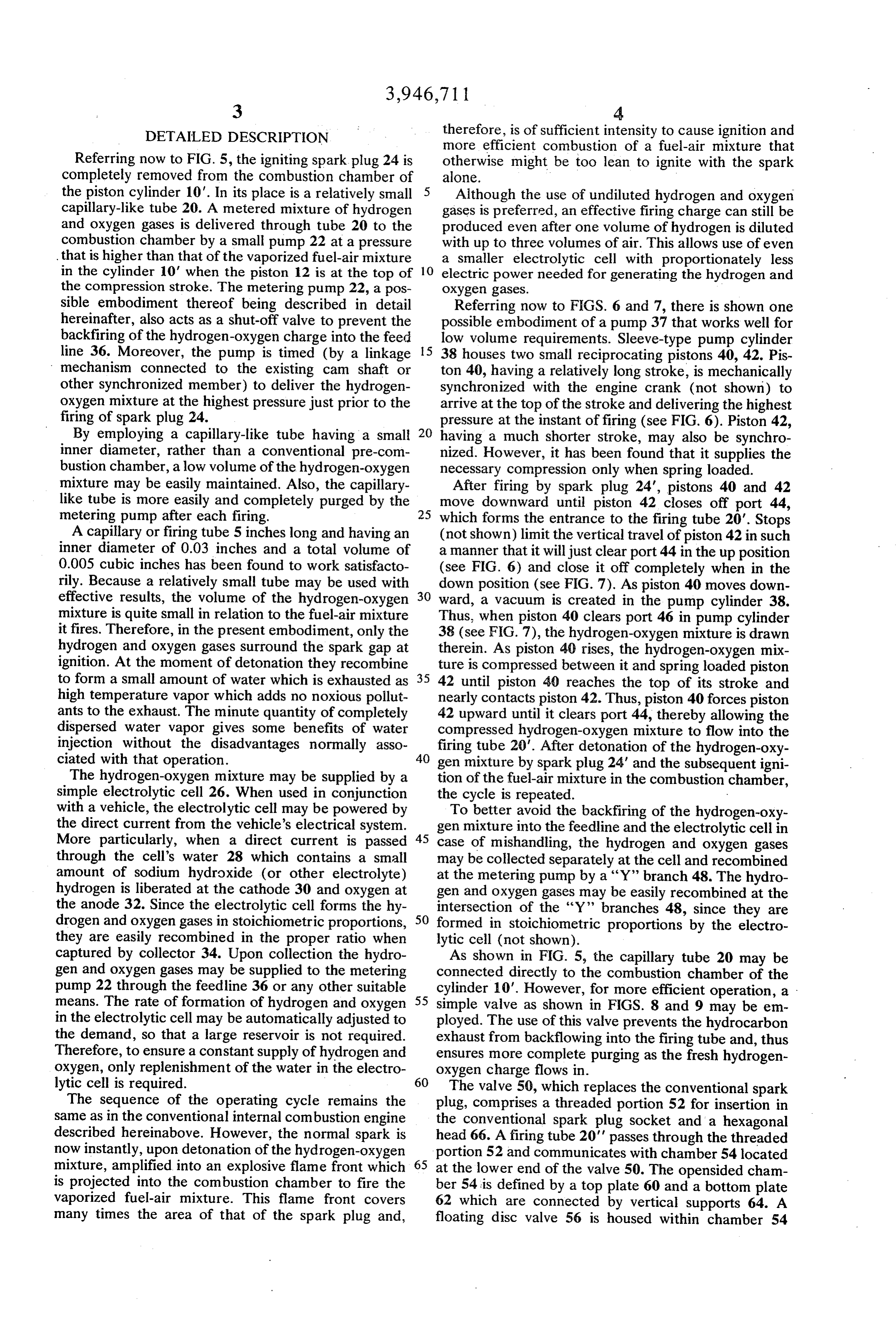
The sequence of the operating cycle remains the plug, comprises a threaded portion 52 for insertion in same as in the conventional internal combustion engine the conventional spark plug socket and a hexagonal described hereinabove. However, the normal spark is head 66. A firing tube 20' passes through the threaded now instantly, upon detonation of the hydrogen-oxygen portion 52 and communicates with chamber 54 located mixture, amplified into an explosive flame front which 65 at the lower end of the valve 50. The opensided cham is projected into the combustion chamber to fire the ber 54 is defined by a top plate 60 and a bottom plate vaporized fuel-air mixture. This flame front covers 62 which are connected by vertical supports 64. A many times the area of that of the spark plug and, floating disc valve 56 is housed within chamber 54
Page 6
immediately below the firing tube 20'. When the hy a housing attached to the other end of said threaded drogen-oxygen charge fires, the disc valve 56 is forced portion and communicating with the main combus downward and the flame front is forced out of the open tion chamber, said housing having open sides, a sides of chamber 54, thereby spreading the flame front first plate abutting the other end of said threaded around the combustion chamber for more complete portion, a second plate having a plurality of aper combustion. As the fuel-air mixture in the combustion tures therein, a support member connecting said chamber is ignited (and the pressure in the firing tube first and second plates and maintaining them in a decreases) disc valve 56 is forced upward closing off substantially parallel relationship, and a disc valve the entrance to firing tube 20'. movably sandwiched between said first and second Apertures 58 in the bottom plate 62 of chamber 54 10 plates; and allow the differential pressure to lift the disc valve 56. transporting means communicating with said housing Since the volume that is controlled through the firing through said first plate for transporting said hydro tube 20' is so small and the distance that disc valve 56 gen and oxygen gases from said precombustion must move is very short, it can be quite thin and light so 15 means to said housing through said hexagonal head that it is easily operated by the changing pressures. For and said threaded portion, instance, the prototype is only 0.005 inches thick and wherein, during detonation of the hydrogen and oxy 5116ths of an inch in diameter. gen gases by said igniting means, said disc valve is It should be understood that although the present forced into contact with said second plate thereby embodiment is shown in conjunction with a 4-cycle 20 forcing said flame front out of said open sides of reciprocating piston engine, the present invention may said housing, and wherein, during firing of the va also be adapted to work with 2-cycle engines, rotary porized fuel-air mixture, when it is present in the engines or any other type of engine which derives its main combustion chamber, said disc valve is forced power from a series of explosive charges of liquid fuel into contact with said first plate and said transport air mixtures. Thus, the foregoing description of a spe 25 ing means thereby preventing backflow of exhaust cific embodiment will so fully reveal the general nature into the pre-combustion means. of the invention that others can, by applying current 2. The combustion system of claim 1 further compris knowledge, readily modify such specific embodiment ing generating means connected to said supply means and/or adapt it for various applications without depart for forming hydrogen and oxygen gases in stoichiomet ing from the generic concept, and therefore such adap 30 ric proportions.
tations and modifications should and are compre 3. The combustion system of claim 1 wherein said hended within the meaning and range of equivalents of igniting means is a spark plug. the disclosed embodiment. Further it is to be under 4. The combustion system of claim 1 wherein said stood that the phraseology and the terminology em supply means is a pump.
ployed herein is for the purposes of description and not 35 5. The combustion system of claim 2 wherein said of limitation. generating means is an electrolytic cell comprising: What is claimed is: a casing;
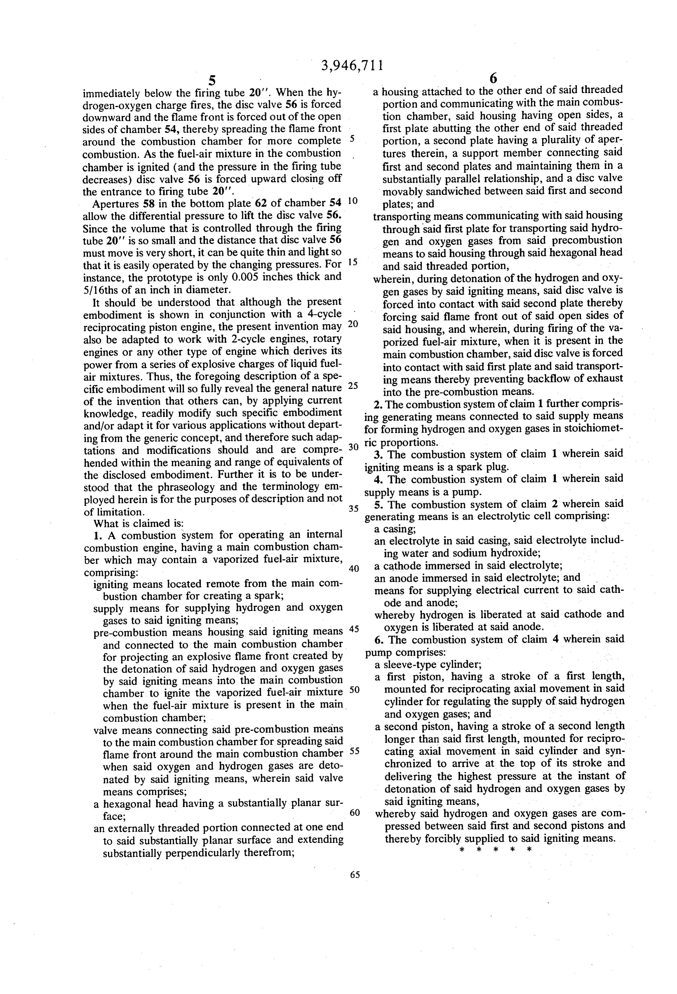
1. A combustion system for operating an internal an electrolyte in said casing, said electrolyte includ combustion engine, having a main combustion cham ing water and sodium hydroxide; ber which may contain a vaporized fuel-air mixture, 40 a cathode immersed in said electrolyte; comprising: an anode immersed in said electrolyte; and igniting means located remote from the main com means for supplying electrical current to said cath bustion chamber for creating a spark; ode and anode;
supply means for supplying hydrogen and oxygen whereby hydrogen is liberated at said cathode and gases to said igniting means; oxygen is liberated at said anode. pre-combustion means housing said igniting means 45 and connected to the main combustion chamber 6. The combustion system of claim 4 wherein said for projecting an explosive flame front created by pump comprises:
a sleeve-type cylinder;
the detonation of said hydrogen and oxygen gases a first piston, having a stroke of a first length, by said igniting means into the main combustion chamber to ignite the vaporized fuel-air mixture 50 mounted cylinder for reciprocating axial movement in said for regulating the supply of said hydrogen when the fuel-air mixture is present in the main and oxygen gases, and - combustion chamber;
valve means connecting said pre-combustion means a second piston, having a stroke of a second length to the main combustion chamber for spreading said longer than said first length, mounted for recipro flame front around the main combustion chamber 55 cating axial movement in said cylinder and syn when said oxygen and hydrogen gases are deto chronized to arrive at the top of its stroke and nated by said igniting means, wherein said valve delivering the highest pressure at the instant of means comprises; detonation of said hydrogen and oxygen gases by a hexagonal head having a substantially planar sur said igniting means, 60 whereby said hydrogen and oxygen gases are com face;
an externally threaded portion connected at one end pressed between said first and second pistons and to said substantially planar surface and extending thereby forciblycksupplied
to said
igniting means.
substantially perpendicularly therefrom;
Provenance
- Collection
- Cited prior art
- Original PDF
- patentimages.storage.googleapis.com →
- Filed
- 1974-04-08
- Pages
- 6
- Method
- pdftotext (the PDF's own text layer) + pdftoppm 300dpi page scans
- Source
- Google Patents bibliographic record
- Granted
- 1976-03-30
- Inventors
- Voorhis F. Wigal
- Transcribed from
- patentimages.storage.googleapis.com →