patent · US20080115744A1
Hydrogen fuel system for an internal combustion engine
22 May 2008
Page 1 — bibliographic record
(19) United States (12) Patent Application Publication (10) Pub. No.: US 2008/0115744 A1
FLESSNER et al. (43) Pub. Date: May 22, 2008 (54) HYDROGEN FUEL SYSTEM FOR AN Publication Classification
INTERNAL COMBUSTON ENGINE
(76) Inventors: STEPHEN M. FLESSNER, Sugar F0IN 3/02 (2006.01) Land, TX (US); Eric S. Flessner, FOIN 3/10 (2006.01)
Sugar Land, TX (US) FI7C I/00 (2006.01) (52) U.S. Cl. .................. 123/3; 220/581; 60/320; 60/299
Correspondence Address: (57) ABSTRACT NCKANCHOLS A hydrogen fuel system for an internal combustion engine PO BOX 16399 includes an electrolyzer for generating hydrogen and oxygen SUGARLAND, TX 7749.66399 gases. The engine exhaust may be recycled through the elec trolyzer where it is converted to hydrogen and oxygen. A water reservoir in fluid communication with the electrolyzer (21) Appl. No.: 11/860,533 maintains the water level in the electrolyzer. The hydrogen and oxygen generated by the electrolyzer may be routed to the (22) Filed: Sep. 24, 2007 internal combustion engine and provide the fuel for the engine. Hydrogen and oxygen not consumed by operation of
Related U.S. Application Data the engine is stored in separate pressurized storage tanks. Expanders lower the pressure of pressurized hydrogen and (63) Continuation of application No. 10/951.290, filed on oxygen for use to power the engine and provide electric power Sep. 27, 2004, now Pat. No. 7,273,044. to the electrolyzer.
Page 2
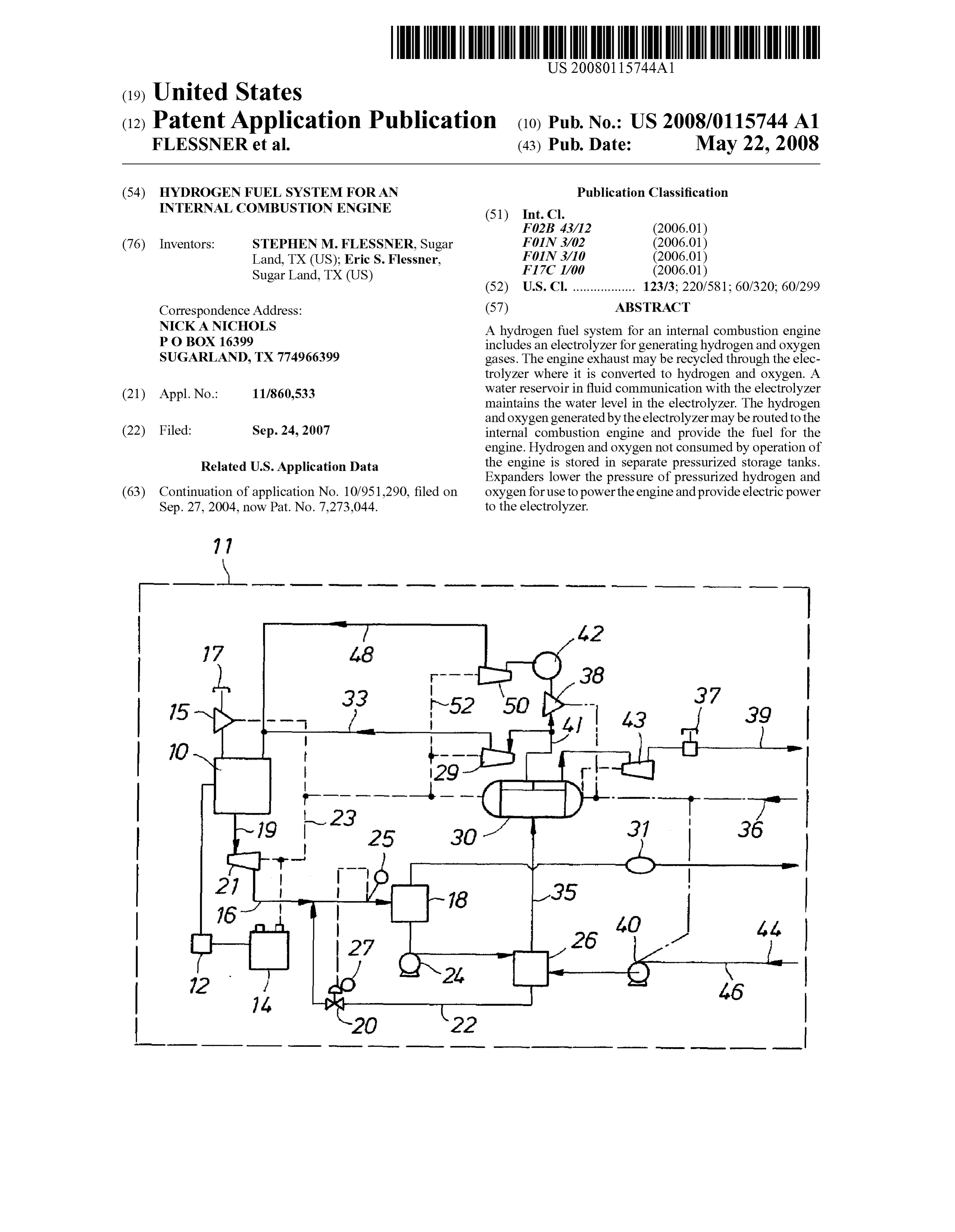
Drawing sheet — no readable text.
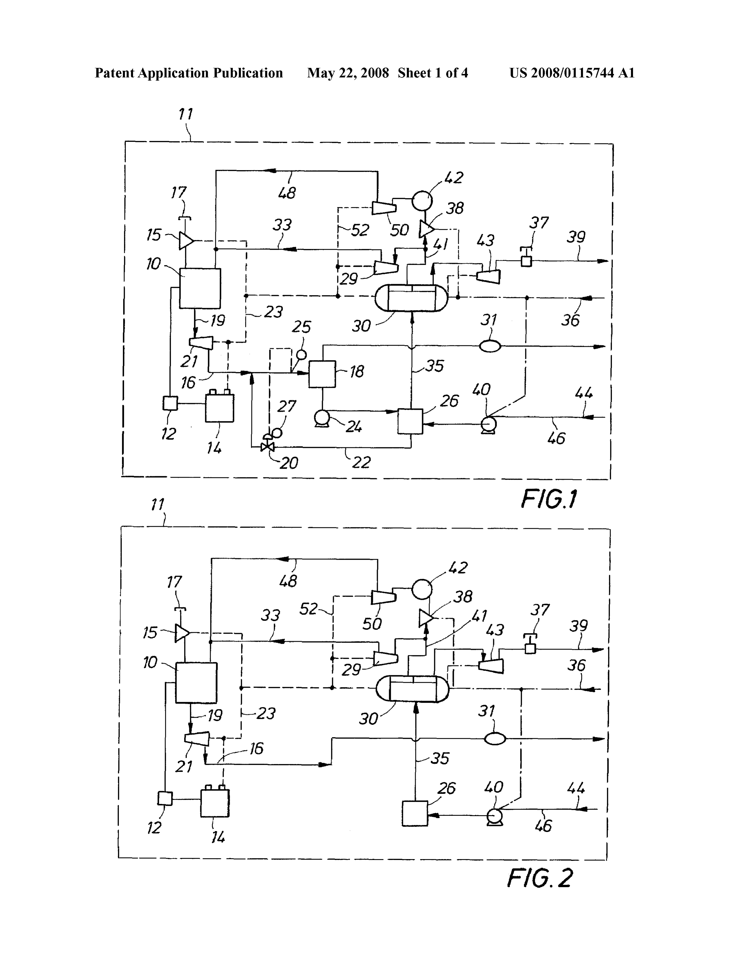
Page 3
Drawing sheet — no readable text.
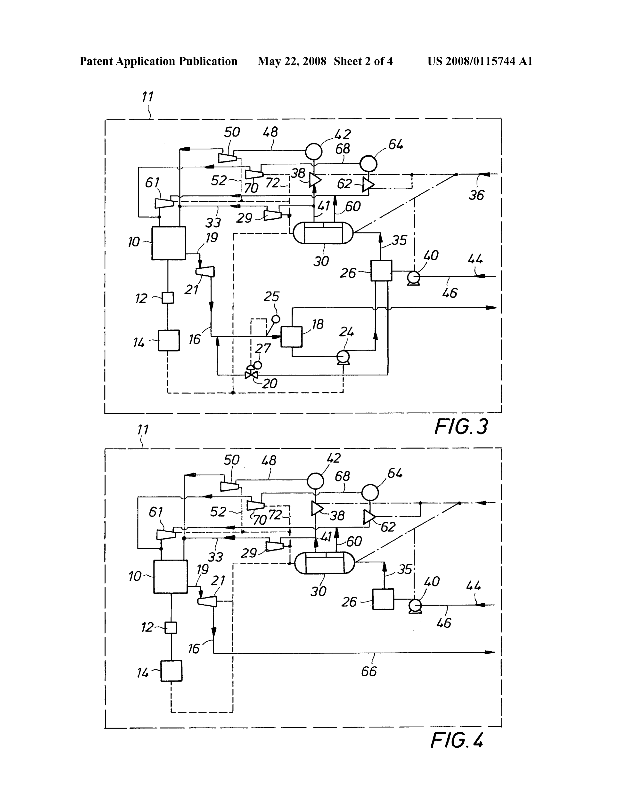
Page 4
Drawing sheet — no readable text.
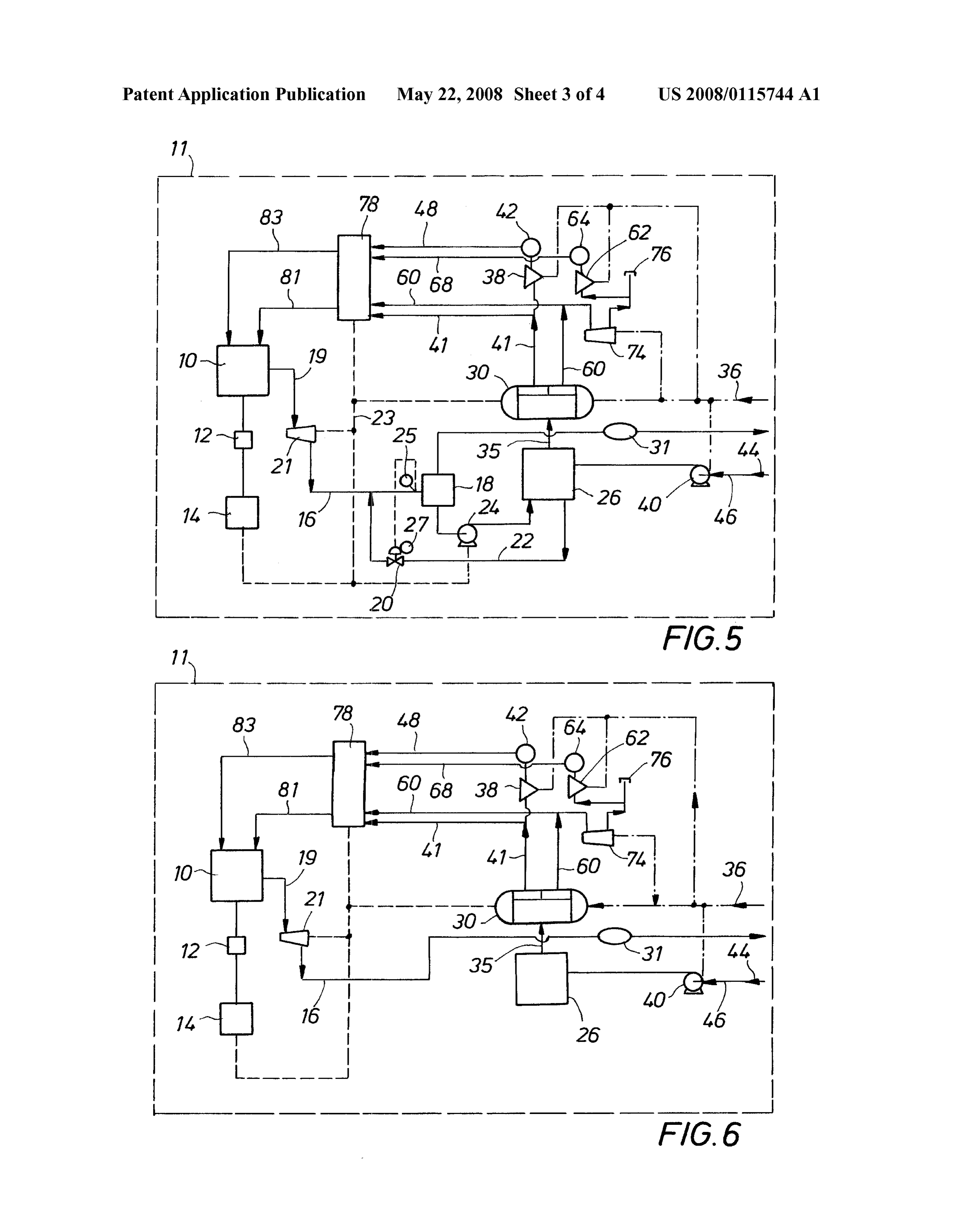
Page 5
Drawing sheet — no readable text.
Page 6
US 2008/O 115744 A1 May 22, 2008
HYDROGEN FUEL SYSTEM FOR AN the electrolyzer may be routed to the internal combustion INTERNAL COMBUSTON ENGINE engine to provide the fuel for the engine. Hydrogen and oxygen generated by the electrolyzer which is not consumed
BACKGROUND OF THE DISCLOSURE by operation of the engine may be stored in pressurized Stor 0001. The present invention relates generally to a vehicle age tanks for use when required to power the internal com bustion engine. Expanders are incorporated in the fuel system having an internal combustion engine, and more particularly, of the invention for lowering the pressure of the pressurized to an internal combustion engine powered by hydrogen fuel. hydrogen and oxygen to the engine pressure requirements 0002. A typical internal combustion engine that is used in and for utilizing the potential energy stored within the pres automobiles, trucks or other vehicles is generally powered by Surized gases to provide a portion of the electrical power gasoline or diesel fuel. A gasoline powered internal combus requirements of the fuel system. The fuel system includes tion engine, however, generates pollutants that are expelled external ports and electrical outlets for connecting to external into the atmosphere. Pollution from internal combustion water and power sources.
engines is a serious problem and many remedies have been proposed. It is known, for example, that adding oxygen into BRIEF DESCRIPTION OF THE DRAWINGS the fuel stream decreases the pollution caused by internal combustion engines. It is also known that hydrogen provides 0010. So that the manner in which the above recited fea a source of clean energy. Furthermore, the combustion of tures, advantages and objects of the present invention are hydrogen generates water as a by-product that may be elec attained can be understood in detail, a more particular trolyzed to form hydrogen and oxygen gases. description of the invention briefly summarized above, may 0003 U.S. Pat. No. 6,257,175 (Mosher et al.) describes be had by reference to the embodiments thereof which are apparatus for generating hydrogen and oxygen from an elec illustrated in the appended drawings. trolysis unit. The gases are gathered separately in the unit and 0011. It is noted, however, that the appended drawings flow to the intake manifold of the engine in separate conduits. illustrate only typical embodiments of this invention and are U.S. Pat. No. 6,659,049 (Baumert et al.) describes a vehicle therefore not to be considered limiting of its scope, for the with a fuel cell system. Electric power from the vehicle's invention may admit to other equally effective embodiments. alternator is used to power an electrolyzer. Hydrogen pro 0012 FIG. 1 is a block diagram of a preferred embodiment duced by the electrolyzer is used as fuel for the fuel cell of the invention adapted for using an air and hydrogen fuel system. The fuel cell system provides electric power for the mixture and recycled engine exhaust vapor to power an inter low power electrical requirements of the vehicle, i.e., light nal combustion engine;
ing, air conditioner, radio, etc., when the engine of the vehicle 0013 FIG. 2 is a block diagram of an alternate embodi is not running. While these apparatus contribute to a reduction ment of the invention depicted in FIG. 1 wherein the engine of pollutant emissions of internal combustion engines, hydro exhaust vapor is passed through a catalytic converter and carbon fuels still provide the primary energy requirements for vented to the atmosphere:
the vehicles. Pollutant emissions of motor vehicles, however, 0014 FIG. 3 is a block diagram of an alternate embodi must still be drastically reduced to have an environmental ment of the invention adapted for using a hydrogen and oxy impact. gen fuel mixture and recycled engine exhaust vapor to power 0004. It is therefore an object of the present invention to an internal combustion engine;
provide an internal combustion engine powered by a hydro 0015 FIG. 4 is a block diagram of an alternate embodi gen fuel system. ment of the invention depicted in FIG. 3 wherein the engine 0005. It is another object of the present invention to pro exhaust vapor is vented to the atmosphere; vide a vehicle having an electrolysis unit for generating 0016 FIG. 5 is a block diagram of an alternate embodi hydrogen and oxygen. ment of the invention depicted in FIG. 3 adapted for mixing 0006. It is another object of the present invention to pro air with pressurized oxygen stored in a storage tank for Sup vide a vehicle fuel system that recycles engine exhaust as plying pressurized air and oxygen to the fuel mixture to power input to an electrolysis unit to generate hydrogen and oxygen an internal combustion engine;
which may be re-used as fuel to power the vehicle. 0017 FIG. 6 is a block diagram of an alternate embodi 0007. It is another object of the present invention to pro ment of the invention depicted in FIG. 5 wherein the engine vide a vehicle fuel system having removable storage capacity exhaust vapor is passed through a catalytic converter and for hydrogen or oxygen generated by an electrolysis unit. vented to the atmosphere:
0008. It is another object of the present invention to pro 0018 FIG. 7 is a block diagram of an alternate embodi vide a vehicle fuel system utilizing expanders to generate ment of the invention depicted in FIG. 5 adapted for storing electric power from high pressure gases. pressurized air in a storage tank for selectively supplying pressurized air and oxygen to the fuel mixture to power an
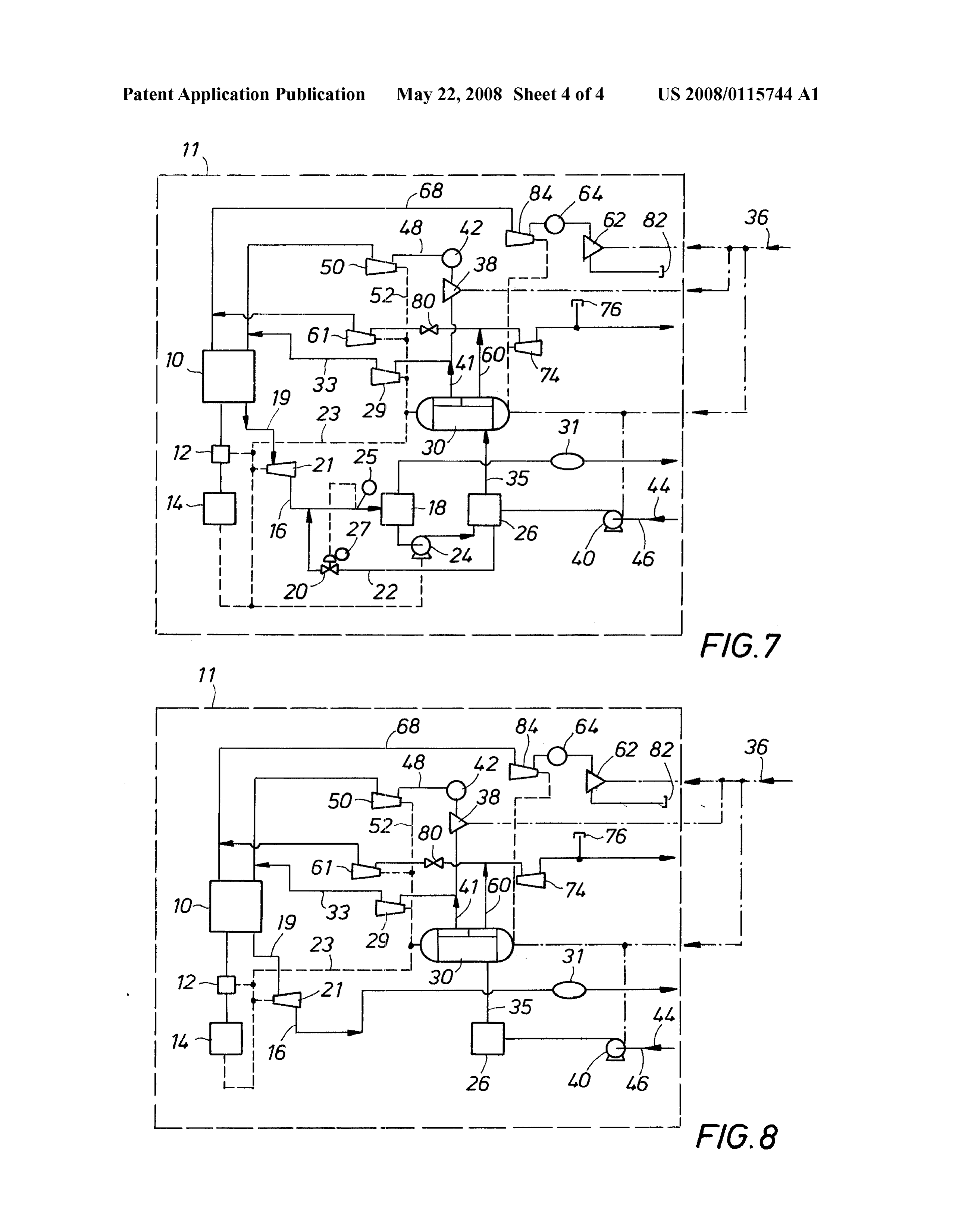
SUMMARY OF THE INVENTION internal combustion engine; and 0019 FIG. 8 is a block diagram of an alternate embodi 0009. In accordance with the present invention, a hydro ment of the invention depicted in FIG. 7 wherein the engine genfuel system for an internal combustion engine includes an exhaust vapor is passed through a catalytic converter and electrolyzer for generating hydrogen and oxygen gases. The vented to the atmosphere.
exhaust of the engine may be recycled through the electro lyZer where it is converted to hydrogen and oxygen which DETAILED DESCRIPTION OF A PREFERRED may be used as fuel for the internal combustion engine. A EMBODIMENT water reservoir in fluid communication with the electrolyzer is provided to maintain the water level in the electrolyzer at an 0020 Referring first to FIG. 1, a block diagram of the fuel optimum operating level. Hydrogen and oxygen generated by system of the present invention is shown operatively con
Page 7
US 2008/O 115744 A1 May 22, 2008
nected to an internal combustion engine 10 of a vehicle 11, mance. The electrolyzer 30 generates hydrogen and oxygen such as an automobile or the like. The fuel system of the by electrolysis. The electrolyzer 30 operates at a pressure of present invention may be retrofit into an existing gasoline about 363 psig. The pressurized hydrogen generated by the powered vehicle or incorporated in a new vehicle design. The electrolyzer 30 is passed through an expander 29 where the internal combustion engine 10 is modified in a known manner hydrogen pressured is lowered to the engine intake pressure to operate with a hydrogen fuel mixture. It is further under and routed to the intake manifold of the engine 10 via conduit stood that the vehicle 11 includes an engine control unit and 33. The oxygen generated by the electrolyzer 30 is passed sensors (not shown in the drawings) electrically and commu through an expander 43 and an air mixer 37 incorporated in a nicatively coupled to the fuel system of the present invention. vent conduit 39 connected to the electrolyzer 30 and vented to 0021. The vehicle 11 powered by the fuel system of the the atmosphere. The expanders 29 and 43 are electrically present invention is equipped with conventional components coupled to the electrolyzer 30.
such as an alternator 12, a battery 14 and other electrical 0026. When the vehicle 11 is operating, electric power to devices. As in conventional vehicles, the alternator 12 pro operate the electrolyzer 30 for production of hydrogen and duces electric power while the engine 10 is operating. The oxygen is provided by an electric circuit comprising the alter battery 14 is used for starting the engine 10, Storing the output nator 12, the battery 14 and the expanders operatively con of the alternator 12 and powering the electrical components of nected to the electrolyzer 30. When the vehicle 11 is not the vehicle 11 while the engine 10 is not operating. operating, hydrogen and oxygen is generated by the electro 0022 Referring still to FIG.1, air and hydrogen are used to lyzer 30 by connecting the vehicle 11 to an external power power the internal combustion engine 10. A compressor 15 Source. Such as a standard residential electrical outlet. The draws air through a port 17 which is open to the atmosphere. vehicle 11 is provided with an electrical outlet 36 for connec Air is pressurized by the compressor 15 to the required engine tion to the external power source. The outlet 36 is electrically pressure and routed to the intake manifold of the engine 10. coupled to the electrolyzer 30, hydrogen compressor 38 and Hydrogen is also routed to the intake manifold of the engine water pump 40 housed in the vehicle 11, thereby forming a 10 from an electrolyzer 30 and a hydrogen storage tank 44 to second electric circuit for operating the electrolyzer 30. form the fuel mixture for powering the engine 10, described in (0027 Hydrogen produced by the electrolyzer 30 when the greater detail hereinafter. vehicle 11 is not operating and connected to an external power 0023 Exhaust vapor exits the engine 10 at a high tempera source is routed via conduit 41 to the compressor 38 and then ture and moderate pressure. The engine exhaust is routed to the hydrogen storage tank 42. The hydrogen is pressurized through a conduit 19 to an expander 21 where the pressure of by the compressor 38 and stored in the storage tank 42 as the exhaust vapor is decreased. The expander 21 is electri pressurized vapor. The storage tank 42 is removable so that it cally coupled to the electrolyzer 30 via a power line 23. The may be replaced with a spare tank of hydrogen when the tank expander 21 converts the potential energy stored within the 42 becomes empty and an external electrical power Source engine exhaust vapor into electric power used to provide part may not be readily available to recharge the tank 42. of the power requirements of the electrolyzer 30. 0028 Hydrogen conduit 48 connects the pressurized 0024. The exhaust vapor from the engine 10 flows through hydrogen storage tank 42 to the intake manifold of the engine the expander 21 at a reduced pressure and is channeled by a 10. Hydrogen which exits the storage tank 42 at a high pres conduit 16 to an air-cooled condenser 18. The exhaust from sure is routed through the expander 50 where the pressure of the engine 10 contains hydrogen, oxygen, water vapor and the hydrogen is decreased to the required engine intake pres potential pollutants, such as NOx, at a temperature of about sure. The expander 50 is electrically coupled to the electro 1000°F. A temperature element or sensor 25 located in the lyzer 30 by a power line 52. The expander 50 converts the conduit 16 upstream from the condenser 18 measures the potential energy stored within the pressurized hydrogen into temperature of the engine exhaust entering the condenser 18 electric power used to power the electrolyzer 30. and communicates the exhaust temperature value to a tem (0029 Periodically, the water reservoir 26 will require perature controller 27 which operates a water valve 20 con replenishment. The vehicle 11 is provided with a water pump nected to the conduit 16 upstream of the temperature element 40 and a water port 44 in fluid communication with the water 25. The valve 20 is connected by a water supply line 22 to a reservoir 26 via a water line 46. The port 44 provides access water reservoir 26. In response to the temperature of the for adding water to the reservoir 26 as is required. Tap water engine exhaust, the controller 27 operates the valve 20 in a may be used to fill the reservoir 26 as needed. However, desired manner to spray water into the exhaust conduit 16, distilled water may also be used if desired. Electrolyte for and thereby cool the engine exhaust vapor to the water Satu aiding the electrolysis process may also be added through the ration point prior to entering the condenser 18, where it is port 44.
condensed into water. Cooling the engine exhaust reduces the 0030 The fuel system of the present invention may be backpressure on the engine 10 as the exhaust vapor passes retrofit into an existing vehicle or incorporated in a new through the condenser 18. A reduction in engine backpressure vehicle design. While the use of hydrogen fuel for an internal improves engine performance through increased horsepower combustion engine is known and understood in the art, the availability. The condensed water exiting the condenser 18 is hydrogen fuel system of the present invention utilizes pumped by a pump 24 to the water reservoir 26. Any gases expanders to recover power from pressurized hydrogen and formed in the condenser 18 are first channeled through a oxygen to Supplement the electric power available to operate catalytic converter 31 for removal of any potential pollutants the electrolyzer and recycles the engine exhaust to produce and then Vented to the atmosphere. more hydrogen and oxygen for fuel and thereby extend the 0025 Referring still to FIG. 1, a water conduit 35 connects driving range of the vehicle. In the operation of a vehicle 11 the water reservoir 26 to the electrolyzer 30. The electrolyzer equipped with the fuel system of the present invention illus 30 is provided with sensors for maintaining the water level in trated in FIG. 1, exhaust vapor from the internal combustion the electrolyzer 30 at an optimum level for efficient perfor engine 10 is cooled as it is routed to a condenser 18 where the
Page 8
US 2008/O 115744 A1 May 22, 2008
exhaust vapor is condensed into water and routed to the water duits to the hydrogen and oxygen outlet ports. In the alternate reservoir 26. Water from the water reservoir 26 is supplied to embodiment of FIG. 6, the exhaust vapor from the engine 10 the electrolyzer 30 where, through the action of electrolysis, is vented to the atmosphere.
hydrogen and oxygen gases are generated. The hydrogen 0036 Referring now to FIG. 7 another alternate embodi generated by the electrolyzer 30 is routed to the engine 10 for ment of the fuel system of the present invention is shown. The powering the vehicle 11. The oxygen generated by the elec embodiment of FIG. 7 is substantially the same as the trolyzer 30 is safely vented to the atmosphere. The fuel sys embodiment of FIG.5 described hereinabove with the excep tem of the present invention generates no pollutant emissions. tion that the oxygen conduit 60 includes a valve 80 incorpo 0031 Referring now to FIG.2, an alternate embodiment of rated therein for controlling the Supply of oxygen from the the fuel system of the present invention is shown. The electrolyzer 30 to the engine 10. The valve 80 is operatively embodiment of FIG. 2 is substantially the same as the coupled to an engine control unit (not shown in the drawings) embodiment of FIG.1 described hereinabove, however, in the for regulating oxygen flow to the engine 10. In addition, embodiment of FIG. 2 the exhaust from the internal combus oxygen generated by the electrolyzer 30 and not routed to the tion engine 10 is vented to the atmosphere rather than being engine 10 is routed through the expander 74 and air mixer 76 recycled. Hydrogen to power the engine 10 is provided by the where it is vented to the atmosphere. The compressor 62 electrolysis of water in the electrolyzer 30 and the hydrogen draws air through a port 82 open to the atmosphere. The air is stored in storage tank 42. pressurized and stored in the storage tank 64. When the 0032. In another embodiment of the invention shown in vehicle 11 is operating, the compressed air in storage tank 64 FIG. 3, the fuel system of the invention is similar to that is passed through an expander 84 and routed to the intake described in FIG. 1 with the exception that hydrogen and manifold of the engine 10 as described hereinabove relating oxygen comprise the fuel to power the engine 10. As illus to FIG.1. In the alternate embodiment of FIG. 8, the exhaust trated in FIG. 3, the exhaust vapors from the engine 10 are vapor from the engine 10 is vented to the atmosphere. cooled and recycled as described hereinabove. Oxygen gen 0037. While preferred and alternate embodiments of the erated by the electrolyzer 30, however, is routed via a conduit invention have been shown and described, other and further 60 and expander 61 to the intake manifold of the engine 10. embodiments of the invention may be devised without depart When the vehicle 11 is offbut connected to an external power ing from the basic scope thereof, and the scope thereof is source, oxygen generated by the electrolyzer 30 is routed to a determined by the claims that follow. compressor 62 where it is pressurized and stored in an oxygen storage tank 64. In an alternate embodiment illustrated in 1. A fuel system for an internal combustion engine, com FIG. 4, the engine exhaust is not recycled, but is instead prising:
vented to the atmosphere through a vent conduit 66. (a) an air intake port open to the atmosphere; 0033 Referring again to FIG. 3, an oxygen conduit 68 (b) a hydrogen storage tank containing pressurized hydro connects the compressed oxygen storage tank 64 to the intake gen operatively connected to said engine; manifold of the engine 10. Oxygen which exits the storage (c) an electrolyzer for generating hydrogen and oxygen; tank 64 at a high pressure is routed through an expander 70 (d) a water reservoir in fluid communication with said where the pressure of the oxygen is decreased to the required electrolyzer;
engine pressure. The expander 70 is electrically coupled to (e) electric circuit means for providing electric power to the electrolyzer 30 by a power line 72. The expander 70 said electrolyzer;
converts the potential energy stored within the pressurized (f) conduit means for routing pressurized hydrogen to said oxygen into electrical power which is used to power the engine; and electrolyzer 30. (g) wherein said conduit means includes expanders dis 0034 Referring now to FIG. 5, another alternate embodi posed therein adapted to lower the pressure of said pres ment of the fuel system of the present invention is shown. The Surized hydrogen routed to said engine. embodiment of FIG. 5 is substantially the same as the 2. The fuel system of claim 1, including an engine exhaust embodiment of FIG.3 described hereinabove with the excep conduit for recycling engine exhaust to said electrolyzer to tion that oxygen generated by the electrolyzer 30 and not generate hydrogen and oxygen by electrolysis. routed to the engine 10 via conduit 60, is routed through an 3. The fuel system of claim 2, wherein said engine exhaust expander 74 where the pressure is lowered to ambient pres is passed through a condenser and condensed into water. Sure. The oxygen is then passed through an air mixer 76 and 4. The fuel system of claim3, including means for injecting the resulting mixture of air and oxygen is routed to the com water into said engine exhaust conduit for cooling exhaust pressor 62 where it is pressurized and stored in storage tank vapor from said engine.
64. 5. The fuel system of claim 2, including a catalytic con 0035 Referring still to FIG. 5, one or more expanders are Verter disposed in said engine exhaust conduit for filtering housed in an expander housing 78. The input manifold of the pollutants from exhaust vapor generated by said engine. housing 78 includes two connectors for air and/or oxygen and 6. The fuel system of claim 1, wherein said conduit means two connectors for hydrogen for illustrative purposes. It is includes a first conduit for routing hydrogen from said hydro understood that the housing 78 may include a greater or fewer gen storage tank to said engine and a second conduit for number of input connectors to match the number of expanders routing hydrogen from said electrolyzer to said engine. housed within the expanderhousing 78. The outputside of the 7. The fuel system of claim 6, including a first compressor housing 78 is provided with an outlet port for connection to a disposed in said first conduit operatively connected to said hydrogen conduit 81 and a second outlet port for connection hydrogen storage tank.
to an oxygen conduit 83 which are in fluid communication 8. The fuel system of claim 1, including an engine exhaust with the intake manifold of the engine 10. The housing 78 is conduit for venting exhaust vapor generated by said engine internally configured to accept and route multiple input con into the atmosphere.
Page 9
US 2008/O 115744 A1 May 22, 2008
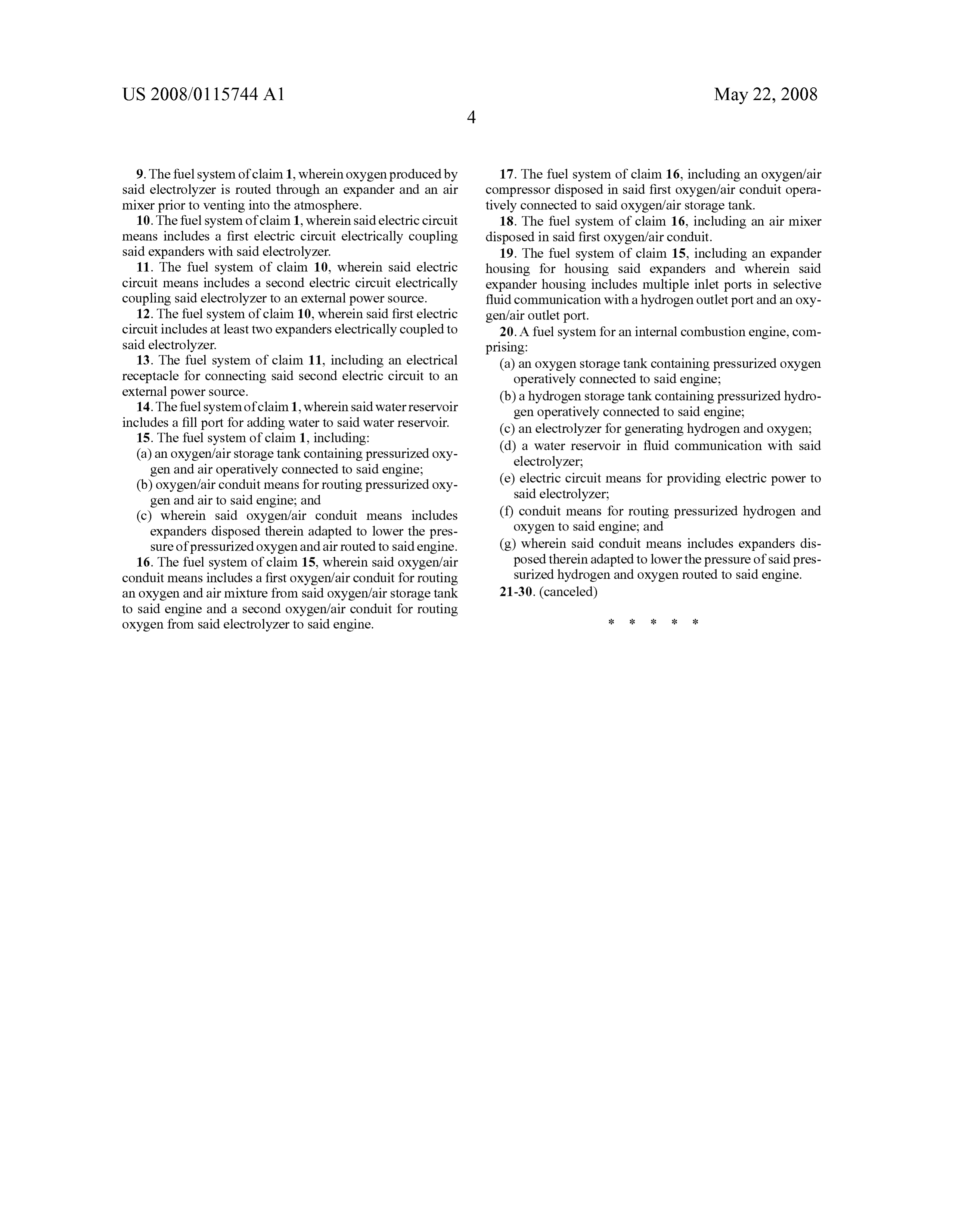
9. The fuel system of claim 1, wherein oxygen produced by 17. The fuel system of claim 16, including an oxygen/air said electrolyzer is routed through an expander and an air compressor disposed in said first oxygen/air conduit opera mixer prior to venting into the atmosphere. tively connected to said oxygen/air storage tank. 10. The fuel system of claim 1, wherein said electric circuit 18. The fuel system of claim 16, including an air mixer means includes a first electric circuit electrically coupling disposed in said first oxygen/air conduit. said expanders with said electrolyzer. 19. The fuel system of claim 15, including an expander 11. The fuel system of claim 10, wherein said electric housing for housing said expanders and wherein said circuit means includes a second electric circuit electrically expander housing includes multiple inlet ports in selective coupling said electrolyzer to an external power source. fluid communication with a hydrogen outlet port and an oxy 12. The fuel system of claim 10, wherein said first electric genfair outlet port.
circuit includes at least two expanders electrically coupled to 20. A fuel system for an internal combustion engine, com said electrolyzer. prising:
13. The fuel system of claim 11, including an electrical (a) an oxygen storage tank containing pressurized oxygen receptacle for connecting said second electric circuit to an operatively connected to said engine; external power source. (b) a hydrogen storage tank containing pressurized hydro 14. The fuel system of claim 1, wherein said water reservoir gen operatively connected to said engine; includes a fill port for adding water to said water reservoir. (c) an electrolyzer for generating hydrogen and oxygen; 15. The fuel system of claim 1, including: (d) a water reservoir in fluid communication with said (a) an oxygen/air storage tank containing pressurized oxy electrolyzer;
gen and air operatively connected to said engine; (e) electric circuit means for providing electric power to (b) oxygen/air conduit means for routing pressurized oxy said electrolyzer;
gen and air to said engine; and (c) wherein said oxygen/air conduit means includes (f) conduit means for routing pressurized hydrogen and expanders disposed therein adapted to lower the pres Oxygen to said engine; and
Sure of pressurized oxygen and air routed to said engine. (g) wherein said conduit means includes expanders dis 16. The fuel system of claim 15, wherein said oxygen/air posed therein adapted to lower the pressure of said pres conduit means includes a first oxygen/air conduit for routing Surized hydrogen and oxygen routed to said engine. an oxygen and air mixture from said oxygen/air storage tank 21-30. (canceled) to said engine and a second oxygen/air conduit for routing oxygen from said electrolyzer to said engine.
Provenance
- Collection
- Patents citing this work
- Pages
- 9
- Method
- pdftotext (the PDF's own text layer) + pdftoppm 300dpi page scans
- Patent office record
- patents.google.com →
- Source
- Google Patents citing-documents table
- Assignee
- Flessner Stephen M
- Inventors
- Stephen M. Flessner; Eric S. Flessner
- Published
- 2008-05-22
- Transcribed from
- patentimages.storage.googleapis.com →