patent · US4458634
Internal combustion engine with hydrogen producing device having water and oil interface level control
10 July 1984
Page 1 — bibliographic record
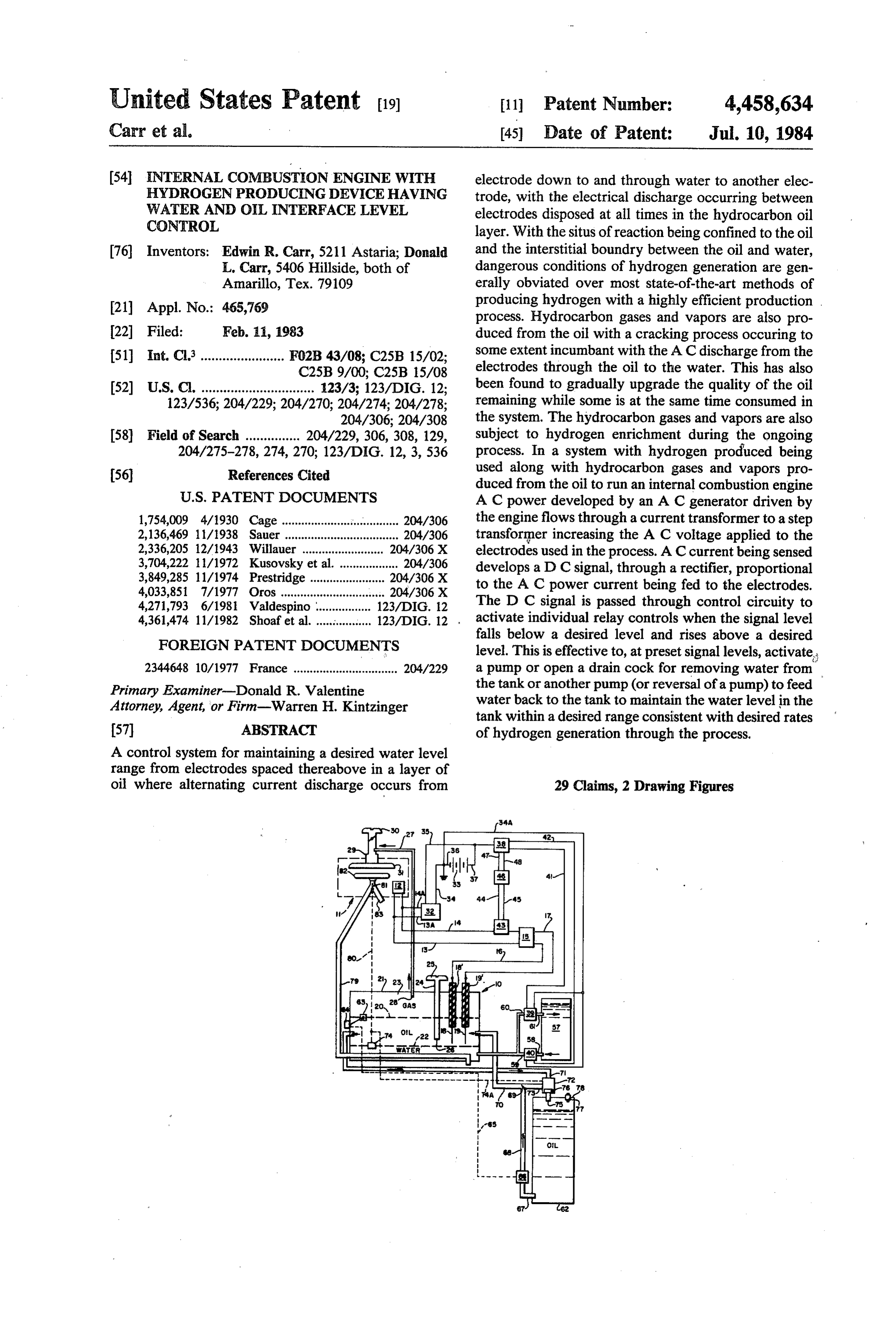
United States Patent (19) 11 Patent Number: 4,458,634 Carr et al. (45) Date of Patent: Jul. 10, 1984 54 INTERNAL COMBUSTION ENGINE WITH electrode down to and through water to another elec HYDROGEN PRODUCING DEVICE HAVING trode, with the electrical discharge occurring between WATER AND OHL INTERFACE LEVEL electrodes disposed at all times in the hydrocarbon oil CONTROL layer. With the situs of reaction being confined to the oil 76) Inventors: Edwin R. Carr, 5211 Astaria; Donald and the interstitial boundry between the oil and water, L. Carr, 5406 Hillside, both of dangerous conditions of hydrogen generation are gen Amarillo, Tex. 79109 erally obviated over most state-of-the-art methods of 21 Appl. No.: 465,769 producing hydrogen with a highly efficient production . process. Hydrocarbon gases and vapors are also pro 22 Filed: Feb. 11, 1983 duced from the oil with a cracking process occuring to 51) Int. Cl........................ F02B 43/08; C25B 15/02; some extent incumbant with the AC discharge from the C25B 9/00; C25B 15/08 electrodes through the oil to the water. This has also 52 U.S. C. ............................... 123/3; 123/DIG. 12; been found to gradually upgrade the quality of the oil 123/536; 204/229; 204/270; 204/274; 204/278; remaining while some is at the same time consumed in 204/306; 204/308 the system. The hydrocarbon gases and vapors are also 58) Field of Search ............... 204/229, 306, 308, 129, subject to hydrogen enrichment during the ongoing 204/275-278, 274, 270; 123/DIG. 12, 3, 536 process. In a system with hydrogen produced being (56) References Cited used along with hydrocarbon gases and vapors pro
duced from the oil to run an internal combustion engine
AC power developed by an AC generator driven by 1,754,009 4/1930 Cage ......................'........... 204/306 the engine flows through a current transformer to a step 2,136,469 11/1938 Sauer ................................... 204/306 2,336,205 12/1943 Willauer ......... 204/306X transformer increasing the AC voltage applied to the electrodes used in the process. AC current being sensed 3,704,222 11/1972 Kusovsky et al. .................. 204/306 develops a D C signal, through a rectifier, proportional 3,849,285 11/1974 Prestridge. . 204/306 X to the AC power current being fed to the electrodes.
4,033,851 7/1977 Oros ............ ... 204/306 X 4,271,793 6/1981 Valdespino . 123/DIG. 12 The D C signal is passed through control circuity to 4,361,474 11/1982 Shoaf et al.................. 123/DIG. 12 . activate individual relay controls when the signal level falls below a desired level and rises above a desired
FOREIGN PATENT DOCUMENTS level. This is effective to, at preset signal levels, activate 2344648 10/1977 France ................................ 204/229 a pump or open a drain cock for removing water from Primary Examiner-Donald R. Valentine the tank or another pump (or reversal of a pump) to feed Attorney, Agent, or Firm-Warren H. Kintzinger water back to the tank to maintain the water level in the tank within a desired range consistent with desired rates (57) ABSTRACT of hydrogen generation through the process. A control system for maintaining a desired water level range from electrodes spaced thereabove in a layer of oil where alternating current discharge occurs from 29 Claims, 2 Drawing Figures
Page 2
Drawing sheet — no readable text.
Page 3
level set points as to allow for small variations in AC
INTERNAL COMBUSTON ENGINE WITH power line current.
HYDROGEN PRODUCING DEVICE HAVING Another object is to provide such a water level con WATER AND OL, NTERFACE LEVEL CONTROL trol not subject to pump water level control actuation by current surges of short duration through a built-in
This invention relates in general to the electrodecom time delay in the control circuit.
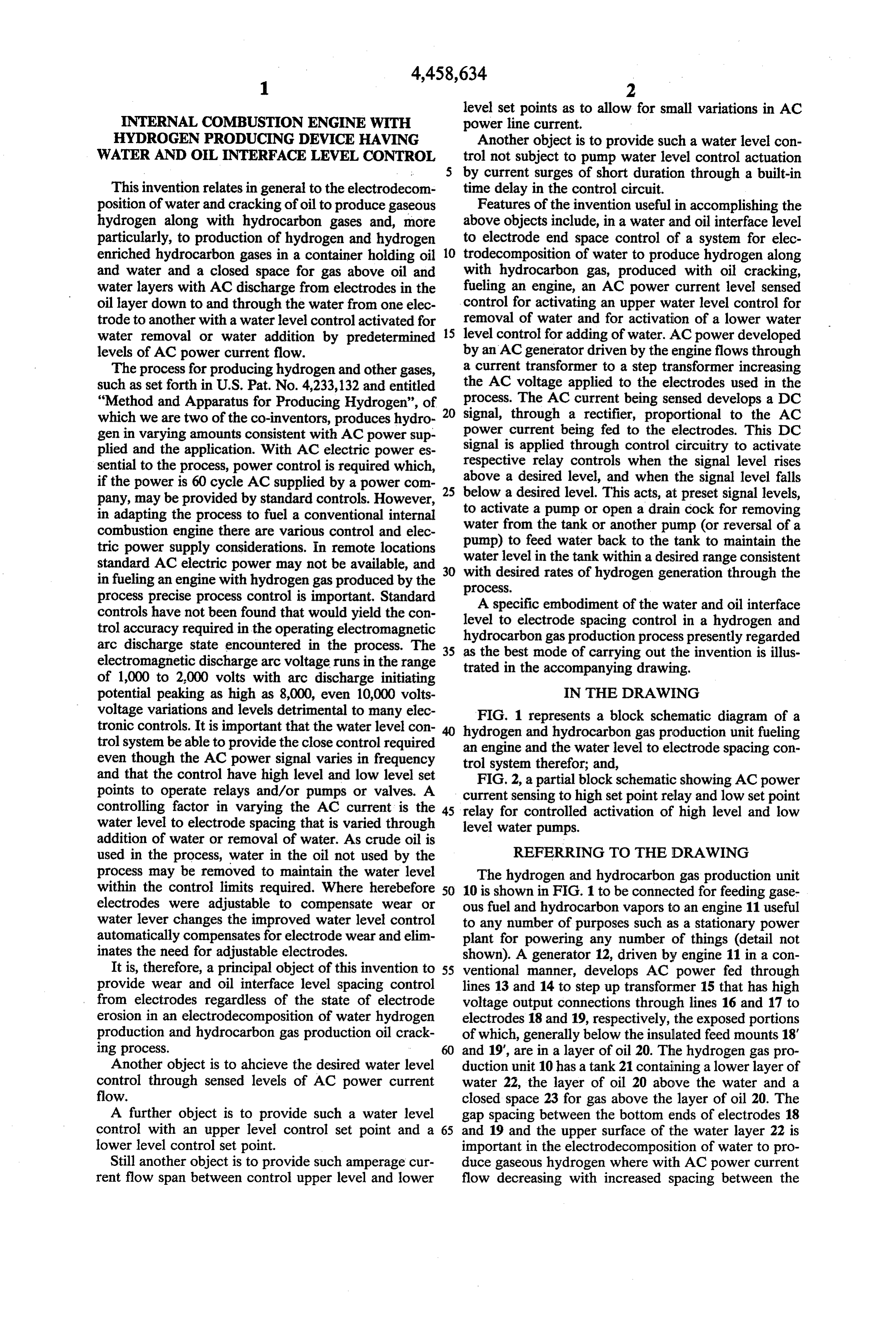
position of water and cracking of oil to produce gaseous Features of the invention useful in accomplishing the hydrogen along with hydrocarbon gases and, more above objects include, in a water and oil interface level particularly, to production of hydrogen and hydrogen to electrode end space control of a system for elec enriched hydrocarbon gases in a container holding oil 10 trodecomposition of water to produce hydrogen along and water and a closed space for gas above oil and with hydrocarbon gas, produced with oil cracking, water layers with AC discharge from electrodes in the fueling an engine, an AC power current level sensed oil layer down to and through the water from one elec control for activating an upper water level control for trode to another with a water level control activated for removal of water and for activation of a lower water water removal or water addition by predetermined 15 level control for adding of water. AC power developed levels of AC power current flow. by an AC generator driven by the engine flows through The process for producing hydrogen and other gases, a current transformer to a step transformer increasing such as set forth in U.S. Pat. No. 4,233,132 and entitled the AC voltage applied to the electrodes used in the "Method and Apparatus for Producing Hydrogen', of process. The AC current being sensed develops a DC which we are two of the co-inventors, produces hydro 20 signal, through a rectifier, proportional to the AC gen in varying amounts consistent with AC power sup power current being fed to the electrodes. This DC plied and the application. With AC electric power es signal is applied through control circuitry to activate sential to the process, power control is required which, respective relay controls when the signal level rises if the power is 60 cycle AC supplied by a power com 25 above a desired level, and when the signal level falls pany, may be provided by standard controls. However, below a desired level. This acts, at preset signal levels, in adapting the process to fuel a conventional internal to activate a pump or open a drain cock for removing combustion engine there are various control and elec pump) water from the tank or another pump (or reversal of a tric power supply considerations. In remote locations to feed water back to the tank to maintain the standard AC electric power may not be available, and 30 water level in the tank within a desired range consistent with desired rates of hydrogen generation through the in fueling an engine with hydrogen gas produced by the process.
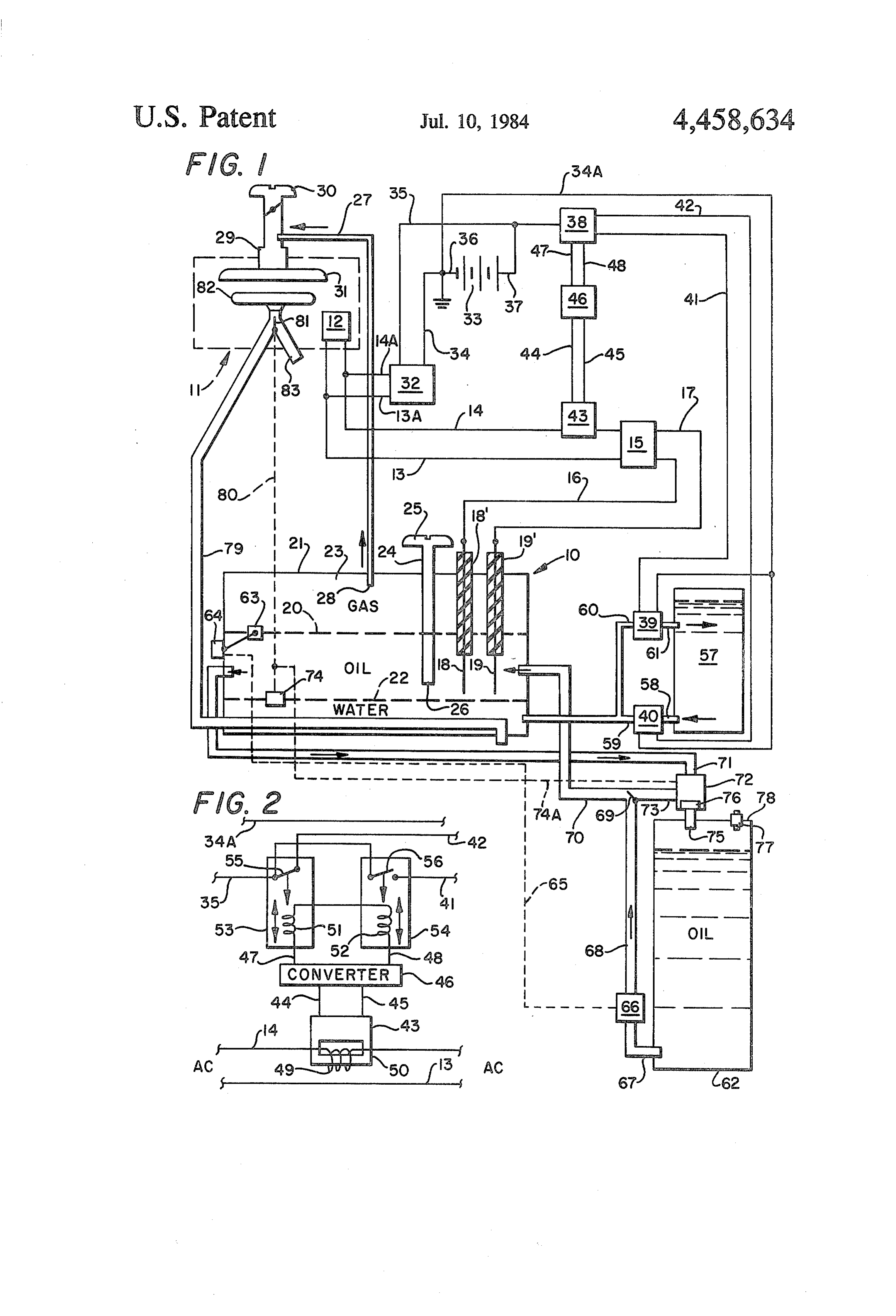
process precise process control is important. Standard A specific embodiment of the water and oil interface controls have not been found that would yield the con level to electrode spacing control in a hydrogen and trol accuracy required in the operating electromagnetic hydrocarbon gas production process presently regarded arc discharge state encountered in the process. The 35 as the best mode of carrying out the invention is illus electromagnetic discharge arc voltage runs in the range trated in the accompanying drawing. of 1,000 to 2,000 volts with arc discharge initiating potential peaking as high as 8,000, even 10,000 volts IN THE DRAWING voltage variations and levels detrimental to many elec FIG. 1 represents a block schematic diagram of a tronic controls. It is important that the water level con hydrogen and hydrocarbon gas production unit fueling trol system be able to provide the close control required an engine and the water level to electrode spacing con even though the AC power signal varies in frequency trol system therefor; and, and that the control have high level and low level set FIG. 2, a partial block schematic showing AC power points to operate relays and/or pumps or valves. A current sensing to high set point relay and low set point controlling factor in varying the AC current is the 45 relay for controlled activation of high level and low water level to electrode spacing that is varied through level water pumps.
addition of water or removal of water. As crude oil is used in the process, water in the oil not used by the REFERRING TO THE DRAWING process may be removed to maintain the water level The hydrogen and hydrocarbon gas production unit within the control limits required. Where herebefore 50 10 is shown in FIG. 1 to be connected for feeding gase electrodes were adjustable to compensate wear or ous fuel and hydrocarbon vapors to an engine 11 useful water lever changes the improved water level control to any number of purposes such as a stationary power automatically compensates for electrode wear and elim plant for powering any number of things (detail not inates the need for adjustable electrodes. shown). A generator 12, driven by engine 11 in a con It is, therefore, a principal object of this invention to 55 ventional manner, develops AC power fed through provide wear and oil interface level spacing control lines 13 and 14 to step up transformer 15 that has high from electrodes regardless of the state of electrode voltage output connections through lines 16 and 17 to erosion in an electrodecomposition of water hydrogen electrodes 18 and 19, respectively, the exposed portions production and hydrocarbon gas production oil crack of which, generally below the insulated feed mounts 18' ing process. and 19", are in a layer of oil 20. The hydrogen gas pro Another object is to ahcieve the desired water level duction unit 10 has a tank 21 containing a lower layer of control through sensed levels of AC power current water 22, the layer of oil 20 above the water and a flow. closed space 23 for gas above the layer of oil 20. The A further object is to provide such a water level gap spacing between the bottom ends of electrodes 18 control with an upper level control set point and a 65 and 19 and the upper surface of the water layer 22 is lower level control set point. important in the electrodecomposition of water to pro Still another object is to provide such amperage cur duce gaseous hydrogen where with AC power current rent flow span between control upper level and lower flow decreasing with increased spacing between the
Page 4
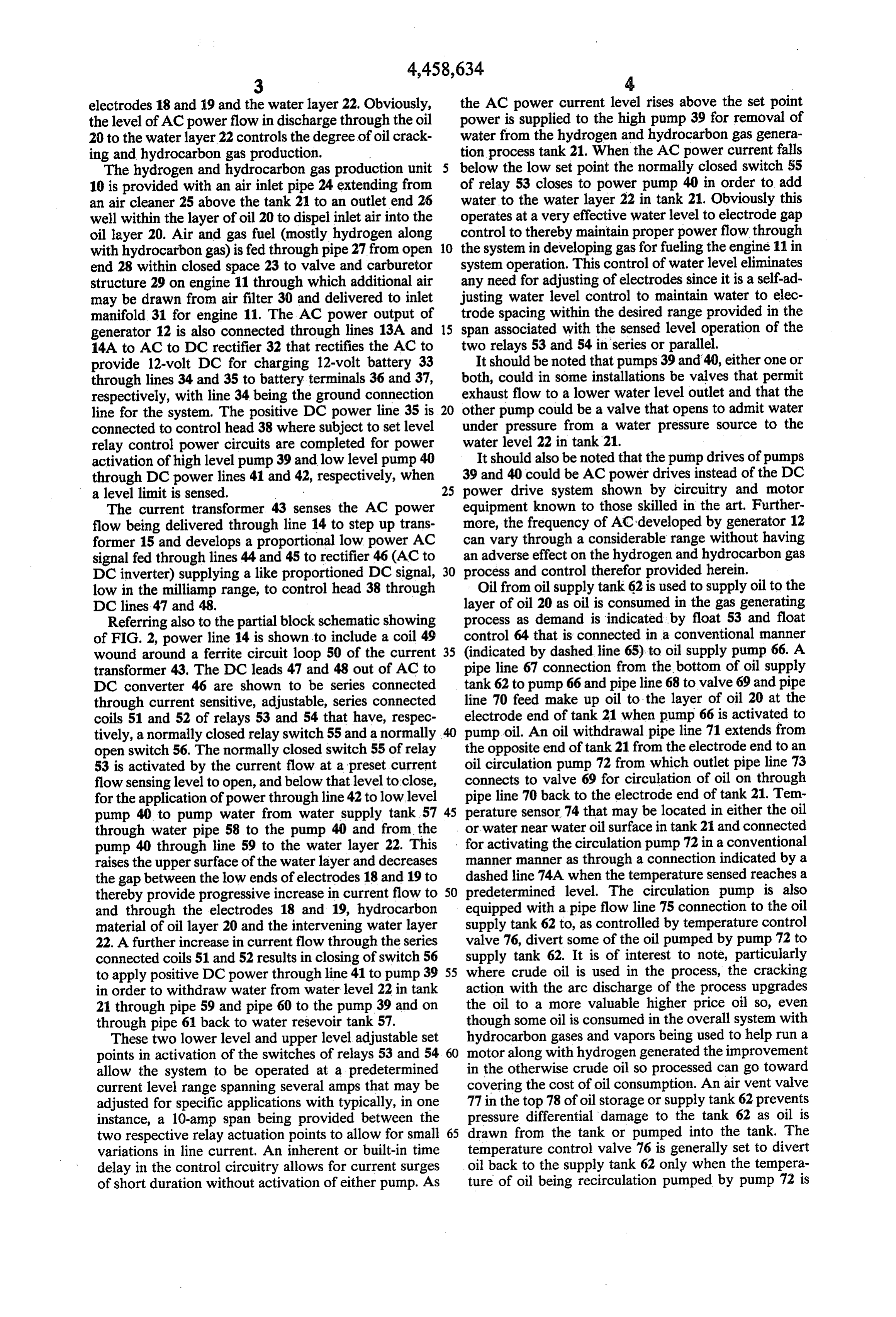
electrodes 18 and 19 and the water layer 22. Obviously, the AC power current level rises above the set point the level of AC power flow in discharge through the oil power is supplied to the high pump 39 for removal of 20 to the water layer 22 controls the degree of oil crack water from the hydrogen and hydrocarbon gas genera ing and hydrocarbon gas production. tion process tank 21. When the AC power current falls The hydrogen and hydrocarbon gas production unit 5 below the low set point the normally closed switch 55 10 is provided with an air inlet pipe 24 extending from of relay 53 closes to power pump 40 in order to add an air cleaner 25 above the tank 21 to an outlet end 26 water to the water layer 22 in tank 21. Obviously this well within the layer of oil 20 to dispel inlet air into the operates at a very effective water level to electrode gap oil layer 20. Air and gas fuel (mostly hydrogen along control to thereby maintain proper power flow through with hydrocarbon gas) is fed through pipe 27 from open O the system in developing gas for fueling the engine 11 in end 28 within closed space 23 to valve and carburetor system operation. This control of water level eliminates structure 29 on engine 11 through which additional air any need for adjusting of electrodes since it is a self-ad may be drawn from air filter 30 and delivered to inlet justing water level control to maintain water to elec manifold 31 for engine 11. The AC power output of trode spacing within the desired range provided in the generator 12 is also connected through lines 13A and 15 span associated with the sensed level operation of the 14A to AC to DC rectifier 32 that rectifies the AC to two relays 53 and 54 in series or parallel. provide 12-volt DC for charging 12-volt battery 33 It should be noted that pumps 39 and 40, either one or through lines 34 and 35 to battery terminals 36 and 37, both, could in some installations be valves that permit respectively, with line 34 being the ground connection exhaust flow to a lower water level outlet and that the line for the system. The positive DC power line 35 is 20 other pump could be a valve that opens to admit water connected to control head 38 where subject to set level under pressure from a water pressure source to the relay control power circuits are completed for power water level 22 in tank 21.
activation of high level pump 39 and low level pump 40 It should also be noted that the pump drives of pumps through DC power lines 41 and 42, respectively, when 39 and 40 could be AC power drives instead of the DC a level limit is sensed. 25 power drive system shown by circuitry and motor The current transformer 43 senses the AC power equipment known to those skilled in the art. Further flow being delivered through line 14 to step up trans more, the frequency of AC developed by generator 12 former 15 and develops a proportional low power AC can vary through a considerable range without having signal fed through lines 44 and 45 to rectifier 46 (AC to an adverse effect on the hydrogen and hydrocarbon gas DC inverter) supplying a like proportioned DC signal, 30 process and control therefor provided herein. low in the milliamp range, to control head 38 through Oil from oil supply tank 62 is used to supply oil to the DC lines 47 and 48. layer of oil 20 as oil is consumed in the gas generating Referring also to the partial block schematic showing process as demand is indicated by float 53 and float of FIG. 2, power line 14 is shown to include a coil 49 control 64 that is connected in a conventional manner wound around a ferrite circuit loop 50 of the current 35 (indicated by dashed line 65) to oil supply pump 66. A transformer 43. The DC leads 47 and 48 out of AC to pipe line 67 connection from the bottom of oil supply DC converter 46 are shown to be series connected tank 62 to pump 66 and pipeline 68 to valve 69 and pipe through current sensitive, adjustable, series connected line 70 feed make up oil to the layer of oil 20 at the coils 51 and 52 of relays 53 and 54 that have, respec electrode end of tank 21 when pump 66 is activated to tively, a normally closed relay switch 55 and a normally pump oil. An oil withdrawal pipe line 71 extends from open switch 56. The normally closed switch 55 of relay the opposite end of tank 21 from the electrode end to an 53 is activated by the current flow at a preset current oil circulation pump 72 from which outlet pipe line 73 flow sensing level to open, and below that level to close, connects to valve 69 for circulation of oil on through for the application of power through line 42 to low level pipe line 70 back to the electrode end of tank 21. Tem pump 40 to pump water from water supply tank.57 45 perature sensor 74 that may be located in either the oil through water pipe 58 to the pump 40 and from the or water near water oil surface in tank 2 and connected pump 40 through line 59 to the water layer 22. This for activating the circulation pump 72 in a conventional raises the upper surface of the water layer and decreases manner manner as through a connection indicated by a the gap between the low ends of electrodes 18 and 19 to dashed line 74A when the temperature sensed reaches a thereby provide progressive increase in current flow to 50 predetermined level. The circulation pump is also and through the electrodes 18 and 19, hydrocarbon equipped with a pipe flow line 75 connection to the oil material of oil layer 20 and the intervening water layer supply tank 62 to, as controlled by temperature control 22. A further increase in current flow through the series valve 76, divert some of the oil pumped by pump 72 to connected coils 51 and 52 results in closing of switch 56 supply tank 62. It is of interest to note, particularly to apply positive DC power through line 41 to pump 39 55 where crude oil is used in the process, the cracking in order to withdraw water from water level 22 in tank action with the arc discharge of the process upgrades 21 through pipe 59 and pipe 60 to the pump 39 and on the oil to a more valuable higher price oil so, even through pipe 61 back to water resevoir tank 57. though some oil is consumed in the overall system with These two lower level and upper level adjustable set hydrocarbon gases and vapors being used to help run a points in activation of the switches of relays 53 and 54 motor along with hydrogen generated the improvement allow the system to be operated at a predetermined in the otherwise crude oil so processed can go toward current level range spanning several amps that may be covering the cost of oil consumption. An air vent valve adjusted for specific applications with typically, in one 77 in the top 78 of oil storage or supply tank 62 prevents instance, a 10-amp span being provided between the pressure differential damage to the tank 62 as oil is two respective relay actuation points to allow for small 65 drawn from the tank or pumped into the tank. The variations in line current. An inherent or built-in time temperature control valve 76 is generally set to divert delay in the control circuitry allows for current surges oil back to the supply tank 62 only when the tempera of short duration without activation of either pump. As ture of oil being recirculation pumped by pump 72 is
Page 5
above a predetermined level in order that oil circulated plurality of electrodes including at least one pair of through the oil layer 20 in tank 21 be readily maintained electrodes with said AC power source means connected at a desired process temperature level without having to for AC power discharge current flow back and forth heat massive supplies of oil in a storage and supply tank from one electrode through the electrode to water level 62. The valve 69 is a self adjusting valve permitting gap, through water to and through the gap of the other flow of oil from oil feed pump 66 or from circulation electrode of said pair of electrodes. pump 72 or balance of oil flow from both pumps when 3. The water layer and electrode end spacing control they are simultaneously pumping. system of claim 2, wherein said AC power current sens Since the process produces more fuel in gas and ing means is a current transformer output connected to vapor form at higher temperature a heat exchanger O said electric power control means, engine exhaust pipeline 79 is passed through the water 4. The water layer and electrode end spacing control layer 22 portion of process tank 21. The temperature system of claim 3, wherein said electric power control sensor 74 is connected through a conventional connec means is switch means responsive to AC power current tion as indicated by dash line 80 for varying valve 81 in level for switch actuation control of the power activa balanced controlled diversion of hot exhaust gases from 15 tion means of said water flow control means... the engine exhaust manifold 82 between direct exhaust 5. The water layer and electrode end spacing control pipe 83 and the pipe line 79 extended through tank 21. system of claim 4, wherein said water flow control This helps, for example, in countering disassociation means includes pump means. - cooling of the water as hydrogen is released from oxy 6. The water layer and electrode end spacing control gen in the electro-disassociation process. 20 system of claim 5, wherein said pump means is a pump Testing of the system was conducted using a 534 and water flow structure controlled for pumping water cubic Ford engine running at 1,750 rp.m. pulling a 70 into said container when the water level is low and the horse power load with the process adding approxi AC power current flow sensed is below a first preset mately an additional 15 horse power to the engine load. level, and for pumping water from said container when Oil consumption was, with proper controls, lowered 25 the water level is high and the AC power current flow into approximately the 2.5 to 4 gallon per hour con sensed is above a preset level. sumption rate at approximately 50 hours into a run. 7. The water layer and electrode end spacing control Further, starting with 39 gravity oil with recycling of system of claim 6, wherein said pump and water flow oil passed through the process tank 21 returned to large structure is connected to a reservoir tank. tankstorage gravity of the stored oil was lowered bene 30 8. The water layer and electrode end spacing control ficially to 36 gravity in approximately 90 hours of run system of claim 6, wherein said pump and water flow ning. structure includes a first pump for pumping water out of Whereas the invention is herein described with re said container; and a second pump for pumping water spect to a preferred embodiment thereof, it should be into said container. . realized that various changes may be made without 35 9. The water layer and electrode end spacing control departing from the essential contribution made by the system of claim 6, wherein there is a current span be teachings hereof. tween control upper level and lower level set points We claim: allowing for relatively small variations in AC power 1. In a water layer and oil layer interface level to line current.
electrode end spacing control system useful in oil crack 10. The water layer and electrode end spacing con ing hydrocarbon gas generation combined with elec trol system of claim 6, wherein there is control level trodecomposition of water hydrogen production: con actuation time delay to prevent pump water level con tainer means for containing, a layer of water at the trol actuation, by current surges of short duration or bottom, a layer of oil above the layer of water, and a current drops of short duration.
space for containing gas above the layer of oil; elec 45 11. The water layer and electrode end spacing con trode means positioned in said container entrained pri trol system of claim 4, wherein there is an AC to DC marily in the layer of oil with an electrode means end to converter in the current transformer output connection water layer gap; AC power source means; AC circuit to said electric power control means. means interconnecting said AC power source means 12. The water layer and electrode end spacing con and said electrode means for feeding AC power 50 trol system of claim 11, wherein adjustable level relay through said electrode means, the gap and water within means is used as said switch means. the container; AC power current sensing means sensing 13. The water layer and electrode end spacing con current level flow through said AC circuit means; elec trol system of claim 12, wherein the adjustable level tric power control means responsive to a predetermined relay means is an upper level set point adjustable level AC current level flow; water flow control means in the 55 relay and a lower level set adjustable level relay. form of fluid flow impetuous means and conduit means 14. The water layer and electrode end spacing con with a line from a water source with power activation trol system of claim 13, wherein there is a current span means for controlling the level of water within said between control upper level and lower level set points container; and AC power source means connected to allowing for relatively small variations in AC power and through said electric power control means to said 60 line current.
water flow control means for controlling the water 15. The water layer and electrode end spacing con level and thereby the electrode means end to water trol system of claim 13, wherein there is control level layer gap in response to predetermined AC current actuation time delay to prevent pump water level con level flow with AC current flow varying inversely with trol actuation by current surges of short duration or variation in electrode means end to water layer gap 65 current drops of short duration.
spacing. 16. The water layer and electrode end spacing con 2. The water layer and electrode end spacing control trol system of claim 4, wherein said power source is an system of claim 1, wherein said electrode means is a AC generator connected via control circuitry to and
Page 6
through said electric power control means to said water 25. The water layer and electrode end spacing con flow control means. trol system of claim 24, wherein said oil flow control 17. The water layer and electrode end spacing con means includes pump means connected for actuation by trol system of claim 16, wherein said AC power source said oil layer surface level sensing and control means; means is said AC generator, and with said AC generator said oil movement driving means includes a pump in driven by an engine connected for using hydrogen and said oil circulation system; temperature sensing control means in said container connected to said pump to con hydrocarbon gases drawn from said container means as trol engine fuel. on and off oil moving driving actuation of said 18. The water layer and electrode end spacing con 10 pumpedand pump;
control means diverting portions of oil said pump to said oil supply storage means.
trol system of claim 17, wherein said switch means is 26. The water layer and electrode end spacing con relay means. trol system of claim 25, wherein said AC power source 19. The water layer and electrode end spacing con means is an AC generator connected via control cir trol system of claim 18, wherein said control circuitry cuitry to and through electric power control means to from said AC generator includes an AC to DC con 15 water flow control means; an internal combustion en Veter. gine is connected for using hydrogen and hydrocarbon 20. The water layer and electrode end spacing con gases drawn from said container means as engine fuel; trol system of claim 19, wherein said control circuitry and said internal combustion engine being provided also includes a system battery connected in the control with an exhaust system with heat exchange means posi circuitry for charge input from said AC to DC con 20 tioned in said container means.
We?ter. 27. The water layer and electrode end spacing con 21. The water layer and electrode end spacing con trol system of claim 26, wherein said exhaust system includes controllable exhaust flow diverting means;
trol system of claim 1, wherein said circuit means inter connecting said AC power source means and said elec 25 temperature sensing control means in said container trode means includes a step up transformer. connected to said controllable exhaust flow diverting 22. The water layer and electrode end spacing con means for control flow of hot exhaust gases through trol system of claim 21, wherein said AC power current said heat exchange means in heating water and oil in sensing means is positioned for sensing AC power cur said container means.
rent flow between said AC power source means and 30 trol28.system The water layer and electrode end spacing con of claim 1, wherein said AC power source said step up transformer.
23. The water layer and electrode spacing control cuitry to andAC means is an generator connected via control cir through electric power control means to system of claim 1, wherein oil supply storage means is water flow control means; an internal combustion en connected through oil supply piping means to said con gine is connected for using hydrogen and hydrocarbon tainer means; oil layer surface level sensing and control 35 gases drawn from said container means as engine fuel; means; and oil flow control means with power activa and said internal combustion engine being provided tion means connected for control by said oil layer sur with an exhaust system with heat exchange means posi face level sensing and control means for controlling the tioned in said container means.
level of oil within said container. 29. The water layer and electrode end spacing con 24. The water layer and electrode end spacing con trol system of claim 28, wherein said exhaust system trol system of claim 23, also including an oil circulation includes controllable exhaust flow diverting means; system with an oil piping system connected for with temperature sensing control means in said container drawing oil from said container and returning oil to said connected to said controllable exhaust flow diverting container, returning oil to said oil supply storage means, means for control flow of hot exhaust gases through and moving oil from said oil supply storage means; and 45 said heat exchange means in heating water and oil in oil movement driving means in said oil piping system said container means.s s sk : k including said oil flow control means.
Provenance
- Collection
- Cited prior art
- Original PDF
- patentimages.storage.googleapis.com →
- Filed
- 1983-02-11
- Pages
- 6
- Method
- pdftotext (the PDF's own text layer) + pdftoppm 300dpi page scans
- Source
- Google Patents bibliographic record
- Granted
- 1984-07-10
- Inventors
- Edwin R. Carr; Donald L. Carr
- Transcribed from
- patentimages.storage.googleapis.com →