patent · US6363923
Oxygen enrichment device for the combustion air of internal combustion engines
2 April 2002
Page 1 — bibliographic record
(12) United States Patent (10) Patent No.: US 6,363,923 B1 Pletschacher (45) Date of Patent: Apr. 2, 2002
(54) OXYGEN ENRICHMENT DEVICE FOR THE (56) References Cited
COMBUSTION AIR OF INTERNAL
COMBUSTION ENGINES U.S. PATENT DOCUMENTS
(75) Inventor: Alexander Pletschacher, Teisendorf 2,593.294. A * 4/1952 Goldberg ..................... 55/406 (DE) 4.265,648 A * 5/1981 Wedege ....................... 55/409 4,292,051 A * 9/1981 Kime ............................ 95/35 5,149,345 A * 9/1992 Bouchard et al. ............. 55/406 (73) Assignee: Christine Pletschacher, Teisendorf 5,553,591 A 9/1996 Yi
FOREIGN PATENT DOCUMENTS
(*) Notice: Subject to any disclaimer, the term of this patent is extended or adjusted under 35 DE 3O 18 634 A1 11/1981 U.S.C. 154(b) by 0 days. DE 42 01 423 A1 7/1993
(21) Appl. No.: 09/582,544 DE 19545 397 A1 6/1997
(22) PCT Fed: Oct. 26, 1999 EP O 237 816 9/1987 (86) PCT No.: PCT/DE99/03425 EP O 394 494 10/1991
S 102(e) Date: Jul. 11, 2000 * cited by examiner
Primary Examiner Noah P. Kamen
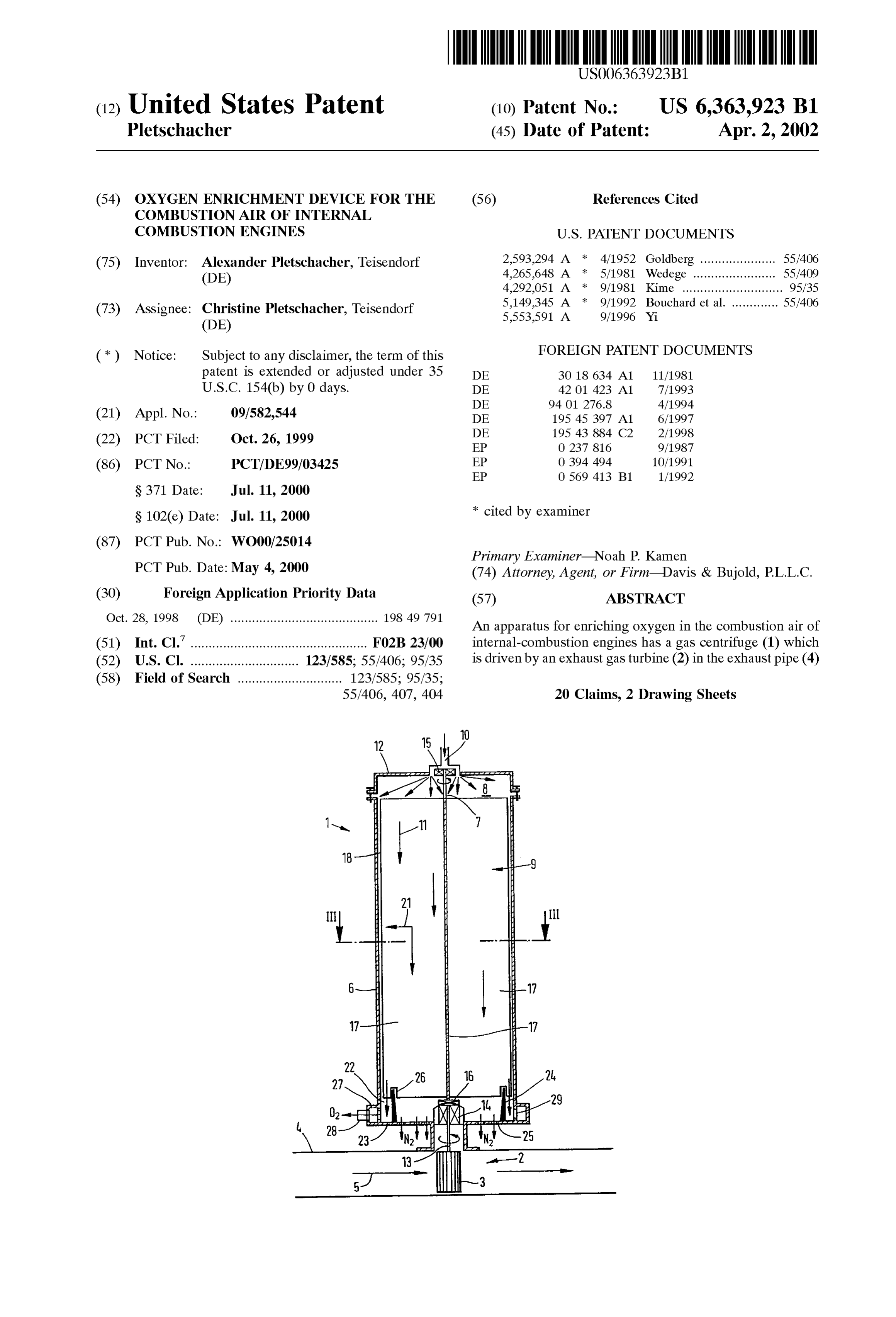
PCT Pub. Date: May 4, 2000 (74) Attorney, Agent, or Firm-Davis & Bujold, P.L.L.C. (30) Foreign Application Priority Data (57) ABSTRACT Oct. 28, 1998 (DE) ......................................... 19849 791 An apparatus for enriching oxygen in the combustion air of (51) Int. Cl. ................................................. FO2B 23/00 internal-combustion engines has a gas centrifuge (1) which (52) U.S. Cl. .............................. 1231585; 55/406; 95/35 is driven by an exhaust gas turbine (2) in the exhaust pipe (4) (58) Field of Search ............................. 123/585; 95/35;
55/406, 407, 404 20 Claims, 2 Drawing Sheets
Page 2
Drawing sheet — no readable text.
Page 3
Drawing sheet — no readable text.
Page 4
OXYGEN ENRICHMENT DEVICE FOR THE (1)
COMBUSTION AIR OF INTERNAL
COMBUSTION ENGINES where p is the density of the gas at atmospheric pressure and m the mass of a molecule of the gas.
This invention relates to an apparatus for enriching For nitrogen (N) with p=1.2505 kgm and oxygen in the combustion air of internal-combustion engines m=4.65175067.10°.k, particle number density n (N) by means of a gas centrifuge. resulting on the rotor axis is thus
BACKGROUND OF THE INVENTION
Since increased oxygen content in the air can increase burnup rate and thereby increase power or reduce fuel = 2.688235051. 1025 m3 consumption, there have for Some time been efforts to = 1.000596565. N. operate internal-combustion engines with oxygen-enriched combustion air.
It is thus known from DE 19543884 C2 to enrich oxygen where N is the Loschmidt number with in the air by gas diffusion through a membrane. Since 15 N, -2.68663.20.m3.
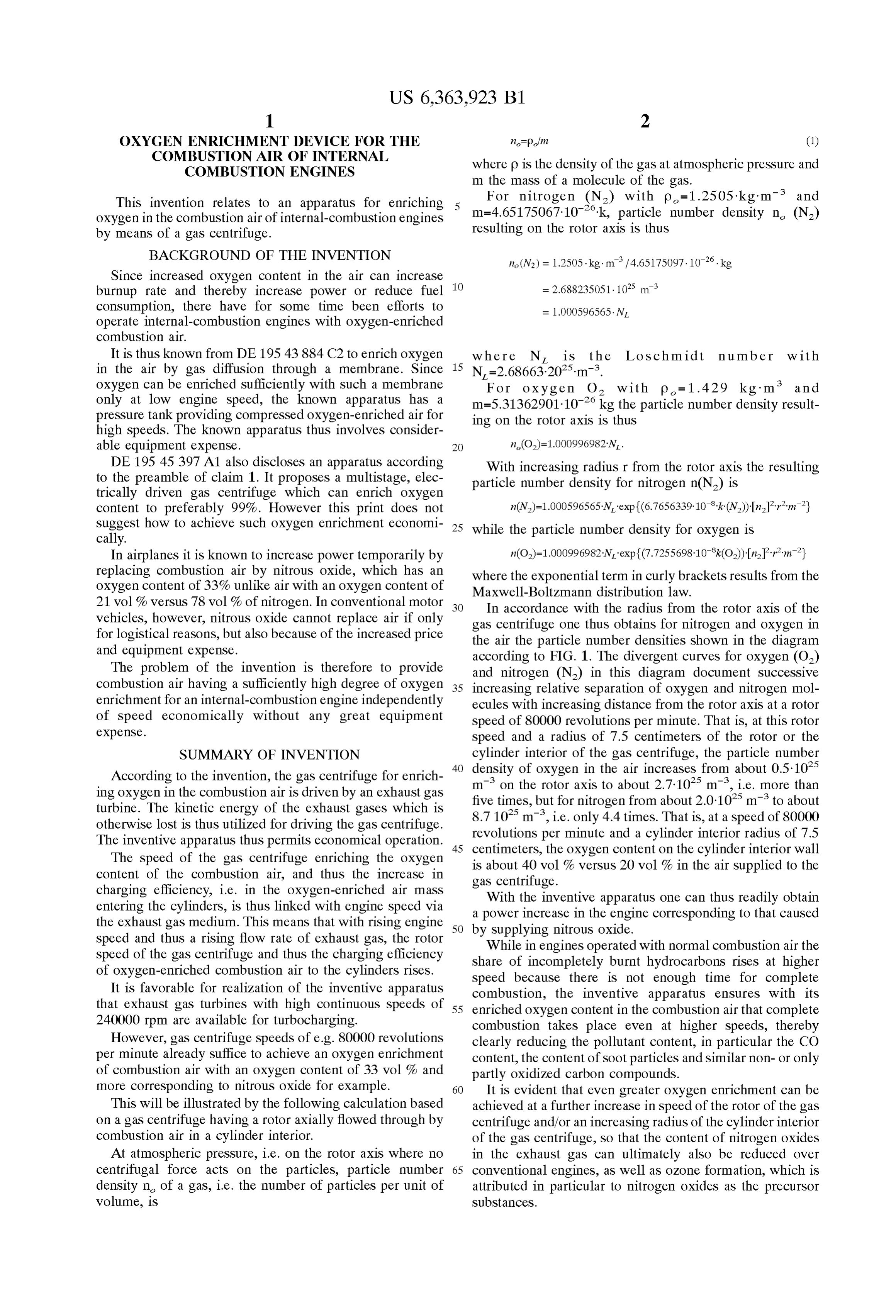
oxygen can be enriched Sufficiently with Such a membrane For oxygen O2 with p = 1.429 kg m and only at low engine Speed, the known apparatus has a m=5.31362901-10° kg the particle number density result preSSure tank providing compressed oxygen-enriched air for ing on the rotor axis is thus high Speeds. The known apparatus thus involves consider able equipment expense. n(O)=1.000996982N,.
DE 19545 397 A1 also discloses an apparatus according With increasing radius r from the rotor axis the resulting to the preamble of claim 1. It proposes a multistage, elec particle number density for nitrogen n(N) is trically driven gas centrifuge which can enrich oxygen content to preferably 99%. However this print does not n(N)=1.000596565-N, exp (6.7656.339:10:k:(N))-In-Pr’m} Suggest how to achieve Such oxygen enrichment economi 25 while the particle number density for oxygen is cally.
In airplanes it is known to increase power temporarily by n(O.)=1.000996982-N, exp (7.7255698-10k(O))-In-Pir’ m} replacing combustion air by nitrous oxide, which has an where the exponential term in curly brackets results from the oxygen content of 33% unlike air with an oxygen content of Maxwell-Boltzmann distribution law.
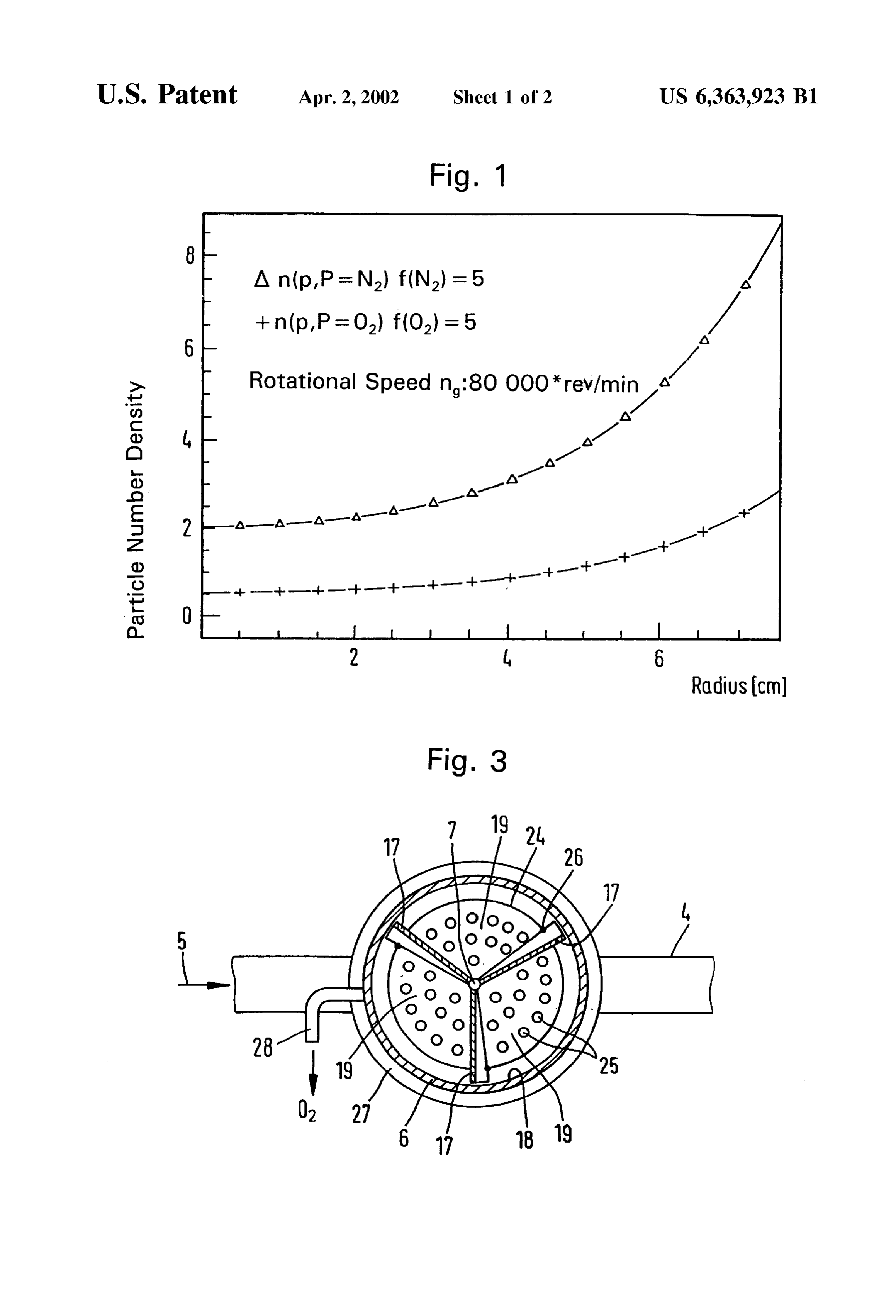
21 vol% versus 78 vol% of nitrogen. In conventional motor In accordance with the radius from the rotor axis of the vehicles, however, nitrous oxide cannot replace air if only gas centrifuge one thus obtains for nitrogen and oxygen in for logistical reasons, but also because of the increased price the air the particle number densities shown in the diagram and equipment expense. according to FIG. 1. The divergent curves for oxygen (O) The problem of the invention is therefore to provide and nitrogen (N) in this diagram document Successive combustion air having a Sufficiently high degree of oxygen 35 increasing relative Separation of oxygen and nitrogen mol enrichment for an internal-combustion engine independently ecules with increasing distance from the rotor axis at a rotor of Speed economically without any great equipment speed of 80000 revolutions per minute. That is, at this rotor expense. speed and a radius of 7.5 centimeters of the rotor or the SUMMARY OF INVENTION cylinder interior of the gas centrifuge, the particle number 40 density of oxygen in the air increases from about 0.5-10
According to the invention, the gas centrifuge for enrich ing oxygen in the combustion air is driven by an exhaust gas m on the rotor axis to about 2.7.10 m, i.e. more than five times, but for nitrogen from about 2.0-10 m to about turbine. The kinetic energy of the exhaust gases which is 8.7 10 m, i.e. only 4.4 times. That is, at a speed of 80000 otherwise lost is thus utilized for driving the gas centrifuge. revolutions
The inventive apparatus thus permits economical operation. 45 centimeters,per minute and a cylinder interior radius of 7.5 The Speed of the gas centrifuge enriching the oxygen is about 40 vol%oxygen the content on the cylinder interior wall versus 20 vol% in the air supplied to the content of the combustion air, and thus the increase in charging efficiency, i.e. in the oxygen-enriched air mass gasWith centrifuge.
entering the cylinders, is thus linked with engine Speed via a powerthe inventive apparatus one can thus readily obtain increase in the engine corresponding to that caused the exhaust gas medium. This means that with rising engine 50 by Supplying nitrous oxide. Speed and thus a rising flow rate of exhaust gas, the rotor
Speed of the gas centrifuge and thus the charging efficiency share of incompletely burntwith
While in engines operated normal combustion air the hydrocarbons rises at higher of oxygen-enriched combustion air to the cylinders rises. Speed because there is not enough time for complete It is favorable for realization of the inventive apparatus combustion, the inventive apparatus ensures with its that exhaust gas turbines with high continuous Speeds of 55 enriched oxygen content in the combustion air that complete 240000 rpm are available for turbocharging. combustion takes place even at higher Speeds, thereby However, gas centrifuge speeds of e.g. 80000 revolutions clearly reducing the pollutant content, in particular the CO per minute already Suffice to achieve an oxygen enrichment content, the content of Soot particles and Similar non- or only of combustion air with an oxygen content of 33 vol% and partly oxidized carbon compounds.
more corresponding to nitrous oxide for example. 60 It is evident that even greater oxygen enrichment can be This will be illustrated by the following calculation based achieved at a further increase in Speed of the rotor of the gas on a gas centrifuge having a rotor axially flowed through by centrifuge and/or an increasing radius of the cylinder interior combustion air in a cylinder interior. of the gas centrifuge, So that the content of nitrogen oxides At atmospheric preSSure, i.e. on the rotor axis where no in the exhaust gas can ultimately also be reduced over centrifugal force acts on the particles, particle number 65 conventional engines, as well as OZone formation, which is density n of a gas, i.e. the number of particles per unit of attributed in particular to nitrogen oxides as the precursor Volume, is Substances.
Page 5
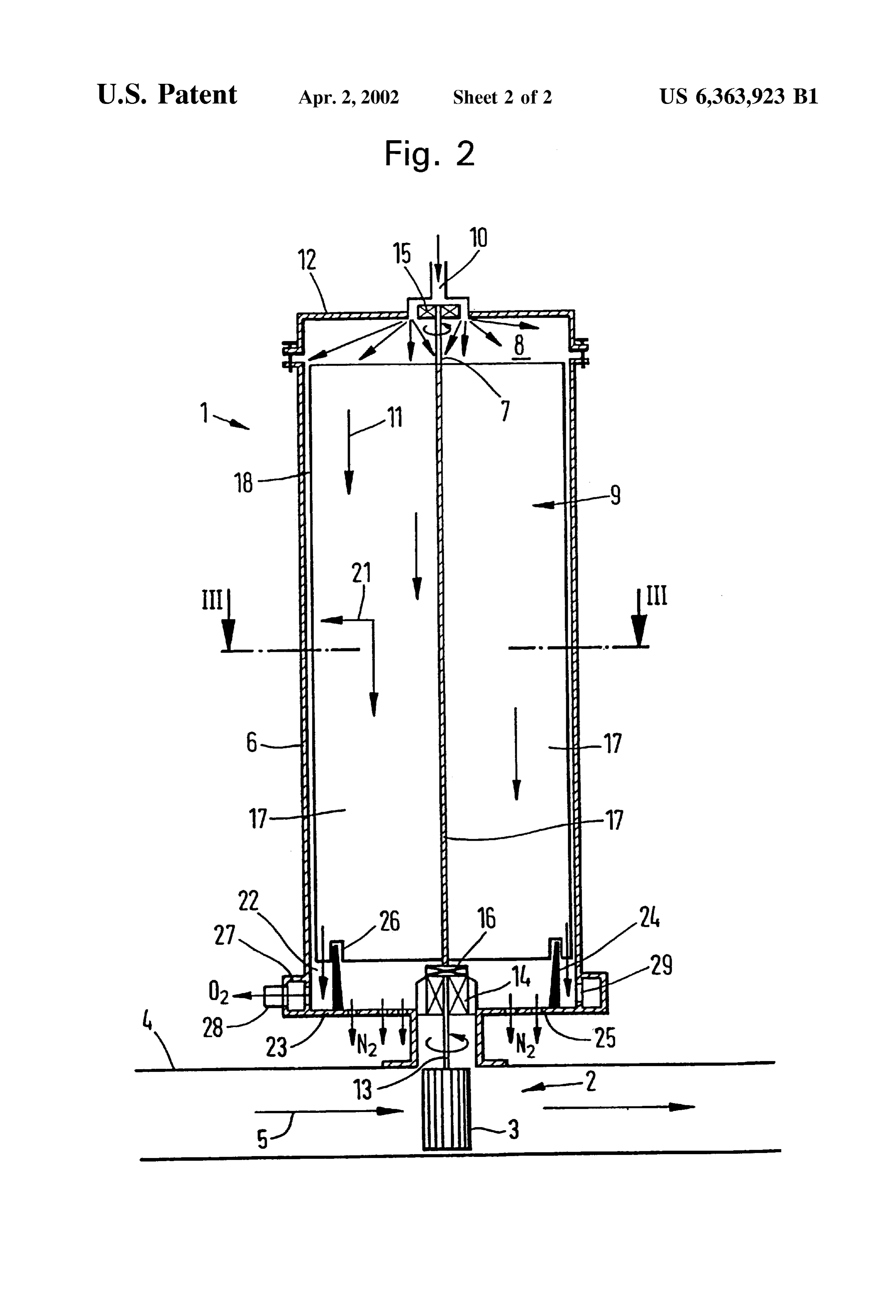
BRIEF DESCRIPTION OF THE DRAWINGS openings 25 provided in end wall 23 between receiving The following examples will serve to illustrate the inven channel 22 and rotor axis 7. In order to Seal receiving channel 22 from the nitrogen-richer, radially inner area with tion further, whereby outlet openings 25, blades 17 have slots 26 into which FIG. 1 shows a diagram plotting oxygen enrichment of the partition 24 protrudes.
air at a given rotor Speed of the gas centrifuge in accordance Oxygen-enriched combustion air 02 enterS ring channel with radius, 27 through ports 29 in cylinder wall 18 and flows to the FIG. 2 shows Schematically a longitudinal Section of an engine via pipe 28 connected to ring channel 27. embodiment of the inventive apparatus, and To increase air flow through gas centrifuge 1 and thus the FIG. 3 shows a Section through the gas centrifuge along oxygen-enriched air mass entering the cylinders of the line III-III according to FIG. 2. engine, rotor blades 17 are disposed on a slight Slant relative to rotor axis 7, as shown in FIG. 3. Instead one can also
DESCRIPTION OF THE PREFERRED provide an additional propeller on rotor axis of rotation 7 EMBODIMENTS while rotor blades 17 can be of axis-parallel form. What is claimed is:
According to FIGS. 2 and 3 the apparatus for enriching 1. An apparatus (1) for enriching an oxygen content of oxygen in the combustion air of an internal-combustion combustion air for an internal-combustion engine, the appa engine (not shown) has gas centrifuge 1 which is driven by ratus comprising a gas centrifuge (1) having a rotor (9) exhaust gas turbine 2. Turbine wheel 3 of exhaust gas rotatably located within a housing (6) of the apparatus, the turbine 2 is disposed for this purpose in exhaust pipe 4 of the rotor (9) being connected to an exhaust gas turbine (2), the internal-combustion engine, being driven by the combustion exhaust gas turbine (2) communicating with combustion exhaust gases of the internal-combustion engine which are exhaust gases (5) of the internal-combustion engine, and the shown by arrows 5. combustion exhaust gases (5) of the internal-combustion engine driving the exhaust gas turbine (2) during operation
Housing 6 of gas centrifuge 1 is flanged to exhaust pipe of the internal-combustion engine;
4 in Such a way that the longitudinal axis of gas centrifuge 25 wherein the rotor (9) has a plurality of blades (17) located 1 is disposed perpendicular to the longitudinal axis of for rotation within an interior of the housing (6) and the exhaust pipe 4. housing (6) defines a diameter in the interior where the Pivotally mounted in cylinder interior 8 of gas centrifuge plurality of blades rotate, and the plurality of blades 1 is rotor 9 which is flowed through axially by combustion have an axial length which is greater than the diameter air shown by arrows 11 and entering interior 8 on one end of the interior of the housing where the plurality of wall 12 via centric inlet opening 10. blades rotate, whereby the rotor (9), during operation of Rotation axis 7 of rotor 9 is thus likewise perpendicular to the internal-combustion engine, rotates and applies a the longitudinal axis of exhaust pipe 4. It at the same time centrifugal force to combustion air, as the combustion extends coaxially to rotation axis 13 of exhaust gas turbine air flows axially along the rotor (9), to force oxygen 2 whose turbine wheel 3 is flowed against radially by 35 enriched combustion air (O) radially away from a exhaust gas 5. Radial and axial bearings 14, 15, 16 are rotational axis (7) of the rotor (9) and facilitate sepa provided for mounting rotor 9 on both sides. ration of the oxygen-enriched combustion air (O) from a remainder of the combustion air.
Rotor 9 has e.g. three blades 17 extending from rotation 2. The apparatus according to claim 1, wherein the axial axis 7 to cylinder interior wall 18 so far that only a gap 40 length of the plurality of blades (17) is greater than twice the receiving tolerances arises on interior wall 18. This forms diameter of the interior of the housing where the plurality of chambers 19 between blades 17 and interior wall 18 which blades rotate.
are flowed through by combustion air 11. Air in chambers 19 3. The apparatus according to claim 1, wherein the circulates in accordance with the rotational Speed of rotor 9 plurality
So that the centrifugal force shown by arrow 21 acts on the 45 (18) of theof housing blades (17) of the rotor (9) and an interior wall molecules in the air in chambers 19, the consequence being plurality of chambers(6)(19)divide the gas centrifuge (1) into a through which the combustion air that oxygen in combustion air 11 is enriched increasingly flows during operation of the internal-combustion engine with the distance from rotation axis 7, i.e. in the area of and clearance is provided between an end of the plurality of cylinder wall 18, as explained above in connection with the blades (17) and the interior wall (18). diagram according to FIG. 1. 50 4. The apparatus according to claim 1, wherein each of the So as to ensure a Sufficient time of action of centrifugal plurality of blades (17) has a similar curvature and the force, blades 17 have accordingly great length in the axial curvature of each of the plurality of blades (17) is slanted in direction. Their axial length is preferably greater than the the same direction, relative to the rotational axis (7) of the radius of cylinder interior 8, in particular more than twice as rotor (9), to increase air flow through the gas centrifuge (1) great as the rotor radius. 55 during operation of the internal-combustion engine. It is self-evident that interior 8 need not necessarily be 5. The apparatus according to claim 1, wherein the cylindrical in form but may also have another rotationally apparatus has a combustion air inlet and an annular channel Symmetric form, e.g. be more or leSS Strongly conic in form. (22) is provided remote from the combustion air inlet for The axial length of blades 17 should then be at least greater receiving the oxygen-enriched combustion air (O) as the than the greatest radius of rotor 9. 60 combustion air flow axially along the apparatus and the Disposed on cylinder interior wall 8 on the outlet-side annular channel (22) has an outlet for Supplying the oxygen axial end of the gas centrifuge is annular receiving channel enriched combustion air (O) to the internal-combustion 22 for oxygen-enriched combustion air, designated “O'”, to engine.
enter. To form receiving channel 22 concentric partition 24 6. The apparatus according to claim 5, wherein a concen is fastened to relevant end wall 23 of housing 6. Oxygen 65 tric partition (24) is located within the housing and the depleted, i.e. nitrogen-rich, air, which is designated “N' in concentric partition (24) separates the annular channel (22) FIG. 1, is released into the atmosphere through outlet from the oxygen-depleted air (N2) outlet.
Page 6
S 6 7. The apparatus according to claim 6, wherein each one have an axial length which is greater than the diameter of the plurality of blades (17) of the rotor (9) has a slot (26) of the interior of the housing where the plurality of formed therein for accommodating the concentric partition blades rotate, whereby the rotor (9), during operation of (24) and facilitating rotation of the rotor (9) relative to the the internal-combustion engine, rotates and applies a concentric partition (24). centrifugal force to combustion air, as the combustion 8. The apparatus according to claim 5, wherein the air flows axially along the rotor (9), to force oxygen housing (6) has a plurality of outlet openings (25) formed enriched combustion air (O) radially away from a therein for discharging oxygen-depleted air (N) from the rotational axis (7) of the rotor (9) and facilitate sepa apparatus, and the plurality of outlet openings (25) are ration of the oxygen-enriched combustion air (O) from located between the rotational axis (7) of the rotor (9) and a remainder of the combustion air; the annular channel (22). each of the plurality of blades (17) has a similar curvature 9. The apparatus according to claim 1, wherein the and the curvature of each of the plurality of blades (17) apparatus has a combustion air inlet and an oxygen-depleted is Slanted in the Same direction, relative to the rotational air (N) outlet, and an annular channel (22) is provided axis (7) of the rotor (9), to increase air flow through the adjacent the oxygen-depleted air (N2) outlet for receiving 15 gas centrifuge (1) during operation of the internal the oxygen-enriched combustion air (O) as the combustion combustion engine; and air flows axially along the apparatus and the annular channel the apparatus has a combustion air inlet and an oxygen (22) has an outlet for Supplying the oxygen-enriched com depleted air (N) outlet, and an annular channel (22) is bustion air (O) to the internal-combustion engine. provided adjacent the oxygen-depleted air (N) outlet 10. The apparatus according to claim 9, wherein a con for receiving the oxygen-enriched combustion air (O) centric partition (24) is located within the housing and the as the combustion air flow axially along the apparatus concentric partition (24) separates the annular channel (22) and the annular channel (22) has an outlet for Supplying from the oxygen-depleted air (N) outlet. the oxygen-enriched combustion air (O2) to the 11. The apparatus according to claim 10, wherein each one of the plurality of blades (17) of the rotor (9) has a slot 25 18.internal-combustion engine. (26) formed therein for accommodating the concentric par concentric partition (24) is locatedtowithin
The apparatus according claim 17, wherein a tition (24) and facilitating rotation of the rotor (9) relative to the concentric partition (24) separates the the housing and annular channel the concentric partition (24). (22) from the oxygen-depleted air (N2) outlet; and 12. The apparatus according to claim 9, wherein the oxygen-depleted air (N) outlet comprises a plurality of each one of the plurality of blades (17) of the rotor (9) has outlet openings (25) formed in the housing (6) for discharg a slot (26) formed therein for accommodating the ing the oxygen-depleted air (N) from the apparatus, and the concentric partition (24) and facilitating rotation of the plurality of outlet openings (25) are located between the rotor (9) relative to the concentric partition (24). 19. The apparatus according to claim 17, wherein the rotational axis (7) of the rotor (9) and the annular channel oxygen-depleted (22). 35 air (N2) outlet comprises a plurality of 13. The apparatus according to claim 1, wherein the outlet openings (25) formed in the housing (6) for discharg housing (6) is connected to an exhaust pipe (4) of the ing the oxygen-depleted air (N) from the apparatus, and the internal-combustion engine Such that the exhaust gas turbine plurality of outlet openings (25) are located between the (2) communicates with combustion exhaust gases (5), as the rotational axis (7) of the rotor (9) and the annular channel combustion exhaust gases (5) flow through the exhaust pipe 40 (22); and (4), to drive the rotor (9). the housing (6) is connected to an exhaust pipe (4) of the 14. The apparatus according to claim 13, wherein the internal-combustion engine Such that the exhaust gas rotational axis (7) of the rotor (9) and a rotational axis of the turbine (2) communicates with combustion exhaust exhaust gas turbine (2) are coaxial with one another and both gases (5), as the combustion exhaust gases (5) flow extend perpendicular to a direction of flow of the combus 45 through the exhaust pipe (4), to drive the rotor (9). tion exhaust gases (5) through the exhaust pipe (4). 20. An apparatus (1) for enriching an oxygen content of 15. The apparatus according to claim 13, wherein the combustion air for an internal-combustion engine, the appa exhaust gas turbine (2) is designed to rotate the rotor (9) at ratus comprising a gas centrifuge (1) having a rotor (9) a rotational speed of about 80,000 revolutions per minute. rotatably located within a housing (6) of the apparatus, the 16. The apparatus according to claim 13, wherein the 50 rotor (9) being connected to an exhaust gas turbine (2), the apparatus further comprises at least one radial bearing and at exhaust gas turbine (2) communicating with combustion least one axial bearing to facilitate rotation of the rotor (9) exhaust gases (5) of the internal-combustion engine, and the and the exhaust gas turbine (2) within the apparatus. combustion exhaust gases (5) of the internal-combustion 17. An apparatus (1) for enriching an oxygen content of engine driving the exhaust gas turbine (2) during operation combustion air for an internal-combustion engine, the appa 55 of the internal-combustion engine;
ratus comprising a gas centrifuge (1) having a rotor (9) wherein the rotor (9) has a plurality of blades (17) located rotatably located within a housing (6) of the apparatus, the for rotation within an interior of the housing (6) and the rotor (9) being connected to an exhaust gas turbine (2), the housing (6) defines a diameter in the interior where the exhaust gas turbine (2) communicating with combustion plurality of blades rotate, and the plurality of blades exhaust gases (5) of the internal-combustion engine, and the 60 have an axial length which is greater than twice the combustion exhaust gases (5) of the internal-combustion diameter of the interior of the housing where the engine driving the exhaust gas turbine (2) during operation plurality of blades rotate, whereby the rotor (9), during of the internal-combustion engine; operation of the internal-combustion engine, rotates wherein the rotor (9) has a plurality of blades (17) located and applies a centrifugal force to combustion air, as the for rotation within an interior of the housing (6) and the 65 combustion air flows axially along the rotor (9), to housing (6) defines a diameter in the interior where the force oxygen-enriched combustion air (O) radially plurality of blades rotate, and the plurality of blades away from a rotational axis (7) of the rotor (9) and
Page 7
facilitate Separation of the oxygen-enriched combus each one of the plurality of blades (17) of the rotor (9) has tion air (O) from a remainder of the combustion air; a slot (26) formed therein for accommodating the each of the plurality of blades (17) has a similar curvature concentric partition (24) and facilitating rotation of the and the curvature of each of the plurality of blades (17) rotor (9) relative to the concentric partition (24); is Slanted in the Same direction, relative to the rotational the oxygen-depleted air (N) outlet comprises a plurality axis (7) of the rotor (9), to increase air flow through the gas centrifuge (1) during operation of the internal of outlet openings (25) formed in the housing (6) for combustion engine; discharging the oxygen-depleted air (N) from the the apparatus has a combustion air inlet and an oxygen 1O apparatus, and the plurality of outlet openings (25) are depleted air (N) outlet, and an annular channel (22) is located between the rotational axis (7) of the rotor (9) provided adjacent the oxygen-depleted air (N) outlet and the annular channel (22); and for receiving the oxygen-enriched combustion air (O) the housing (6) is connected to an exhaust pipe (4) of the as the combustion air flow axially along the apparatus internal-combustion engine Such that the exhaust gas and the annular channel (22) has an outlet for Supplying turbine (2) communicates with combustion exhaust the oxygen-enriched combustion air (O) to the 15 internal-combustion engine; gases (5), as the combustion exhaust gases (5) flow a concentric partition (24) is located within the housing through the exhaust pipe (4), to drive the rotor (9). and the concentric partition (24) separates the annular k k k k k channel (22) from the oxygen-depleted air (N) outlet;

Provenance
- Collection
- Cited prior art
- Original PDF
- patentimages.storage.googleapis.com →
- Filed
- 1999-10-26
- Pages
- 7
- Method
- pdftotext (the PDF's own text layer) + pdftoppm 300dpi page scans
- Source
- Google Patents bibliographic record
- Granted
- 2002-04-02
- Inventors
- Alexander Pletschacher
- Transcribed from
- patentimages.storage.googleapis.com →