patent · US5399251
System for generating hydrogen and oxygen
21 March 1995
Page 1 — bibliographic record
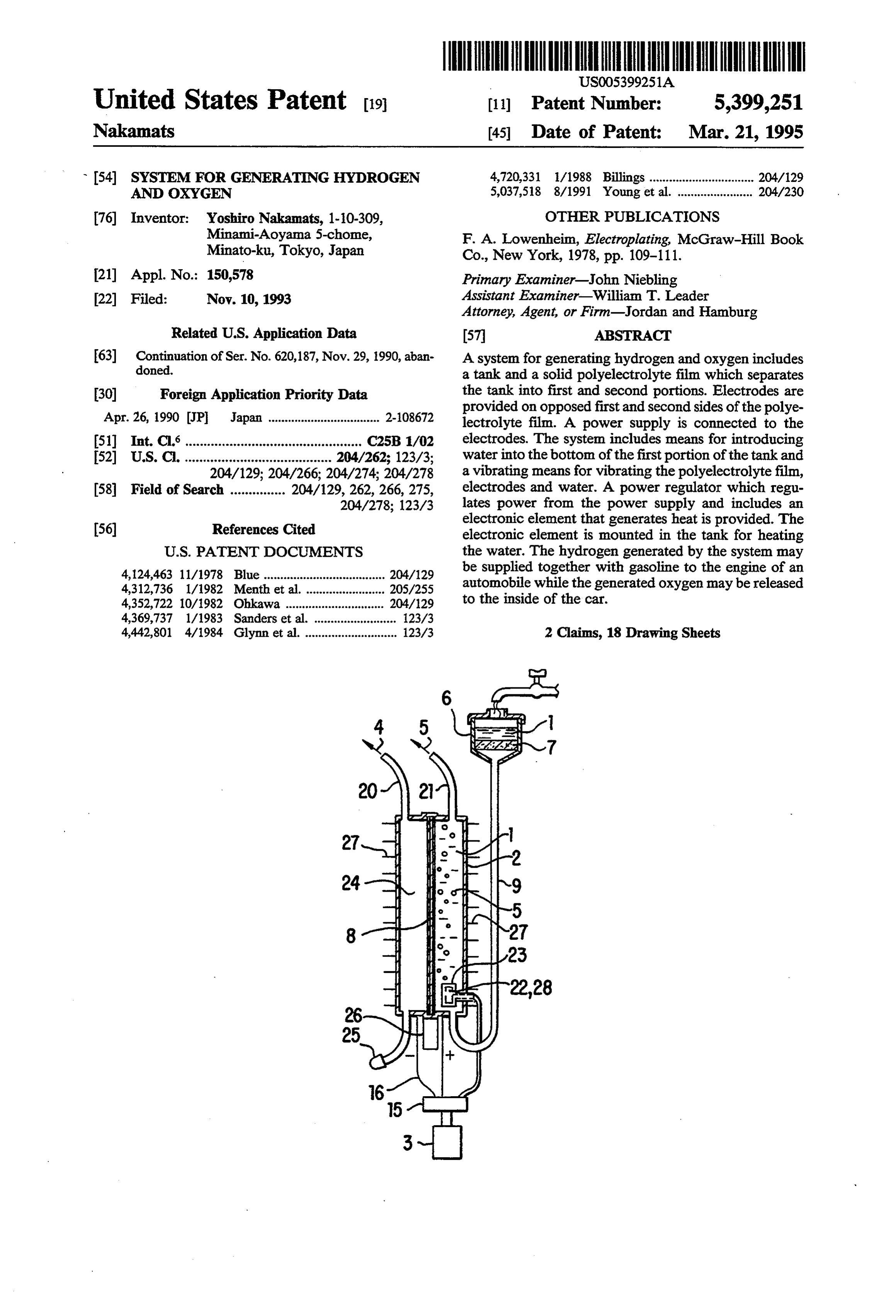
United States Patent 19 11) Patent Number: 5,399,251 Nakamats 45 Date of Patent: Mar. 21, 1995 54 SYSTEM FOR GENERATING HYDROGEN 4,720,331 1/1988 Billings ................................ 204/129 AND OXYGEN 5,037,518 8/1991 Young et al. ...................... 204/230 76 Inventor: Yoshiro Nakamats, 1-10-309, OTHER PUBLICATIONS Minami-Aoyama 5-chome, F. A. Lowenheim, Electroplating, McGraw-Hill Book
Minato-ku, Tokyo, Japan Co., New York, 1978, pp. 109-111.
(21) Appl. No.: 150,578 Primary Examiner-John Niebling 22 Filed: Nov. 10, 1993 Assistant Examiner-William T. Leader Attorney, Agent, or Firm-Jordan and Hamburg
Related U.S. Application Data 57 ABSTRACT 63 Continuation of Ser. No. 620,187, Nov. 29, 1990, aban A system for generating hydrogen and oxygen includes doned. a tank and a solid polyelectrolyte film which separates 30 Foreign Application Priority Data the tank into first and second portions. Electrodes are Apr. 26, 1990 (JP Japan .................................. 2-08672 provided on opposed first and second sides of the polye lectrolyte film. A power supply is connected to the 511 Int. Cl................................................ C25B 1/02 electrodes. The system includes means for introducing 52 U.S. C. ........................................ 204/262; 123/3; water into the bottom of the first portion of the tank and 204/129; 204/266; 204/274; 204/278 a vibrating means for vibrating the polyelectrolyte film, 58 Field of Search ............... 204/129, 262, 266, 275, electrodes and water. A power regulator which regu 204/278; 123/3 lates power from the power supply and includes an
electronic element that generates heat is provided. The electronic element is mounted in the tank for heating
4,124,463 11/1978 Blue ..................................... 204/29 be supplied together with gasoline to the engine of an 4,312,736 1/1982 Menth et al......................... 205/255 automobile while the generated oxygen may be released 4,352,722 10/1982 Ohkawa .............................. 204/129 to the inside of the car.
4,369,737 1/1983 Sanders et al. ......................... 123/3 4,442,801 4/1984 Glynn et al. ............................ 123/3 2 Claims, 18 Drawing Sheets
Page 2
Drawing sheet — no readable text.
Page 3
Drawing sheet — no readable text.
Page 4
Drawing sheet — no readable text.
Page 5
Drawing sheet — no readable text.
Page 6
Drawing sheet — no readable text.
Page 7
Drawing sheet — no readable text.
Page 8
Drawing sheet — no readable text.
Page 9
Drawing sheet — no readable text.
Page 10
AVERAGE EFFECTIVE PRESSURE
AND NO DENSITY
FIG. 3
NO EXHAUSTRATIO AT IGNITION TIME
FOR MBT WHEN HYDROGENSADDED
ROTATING SPEED n=1000 rpm. AIR VOLUMEGo = 3.0 x 10³kg/s
IGNITION TIME FOR MBT
EXCESSIVE AIR RATO X
Page 11
INFLUENCE OF IGNON TIME ON INDICATED
HORSEPOWER AND EXHAUSTS OF HC, CO AND NO
44 - ROTATING SPEED n=1000 rpm AIR VOLUME Go=30x103kg/s
3.42 EXCESSIVE AIR RATIO 51.2
IGNITION TIME (BTDCdegCA)
Page 12
Drawing sheet — no readable text.
Page 13
Drawing sheet — no readable text.
Page 14
Drawing sheet — no readable text.
Page 15
CHANGE OF PRESSURE WITHINCYLNDER
ROTATING SPEED n=1000rpm AIR VOLUME GO=30x103kg/s
EXCESSIVE AIR RATIO X=1.0
IGNITION TIME BTDC10 degCA
ANGLE OF CRANK deg)
Page 16
IGNITION TIME GIVING MAXIMUM OUTPUT (IGNITION TIME FORMBT)
ROTATING SPEED n=1000 rpm AIR VOLUME GO = 3.0 x 10³kg/s
EXCESSIVE AR RAO X
TEMPERATURE OF EXHAUST WHEN ADDING HYDROGEN
ROTATING SPEED n=1000 rmp AIR VOLUME GO = 3.0 x 10³kg/s EXCESSIVE AIR RATIO =l.
IGNITION TIME (BTDCdegCA)
Page 17
AVERAGE VALUE, STANDARD DEVIATION AND
FLUCTUATION RATIO OF MAXIMUMOUTPUT
AVERAGEWALUE OF
MAXIMUM PRESSURE
ROATING SPEED
AIR WOLUME
320|\ IGNiflón timE FORMBT 20s as
2 o 9.
5- a RATIO FLUCTUATION C 29N L 3 55 5-2510 10 E sist s
OU -
2 L
Page 18
INDICATED HORSEPOWER WHEN EXCESSIVE
5.O AIR RATIOS CHANGED
AIR VOLUME GO = 3.0x 10³ kg/s
SIGNITION TIME FOR MBT
EXCESSIVE AIR RATIOM
INDICATED THERMAL EFFICENCY WHEN EXCESSIVE
45 AR RATIO IS CHANGED
ROTATING SPEED n=1000rpm
AIR VOLUME GO = 30x10-3kg/s IGNITION TIME BTDC30 degCA
EXCESSIVE AIR RATO X
Page 19
Drawing sheet — no readable text.
Page 20
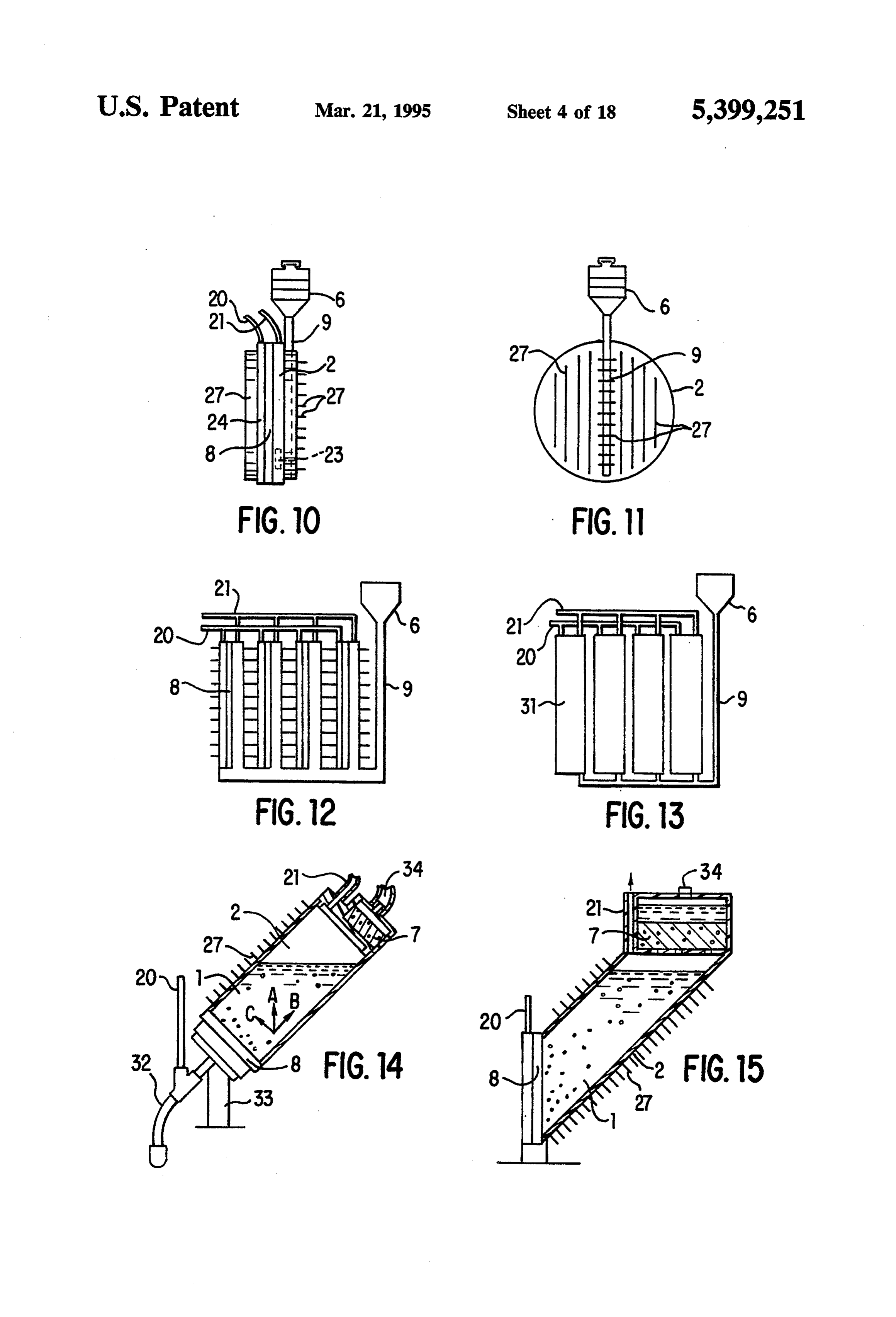
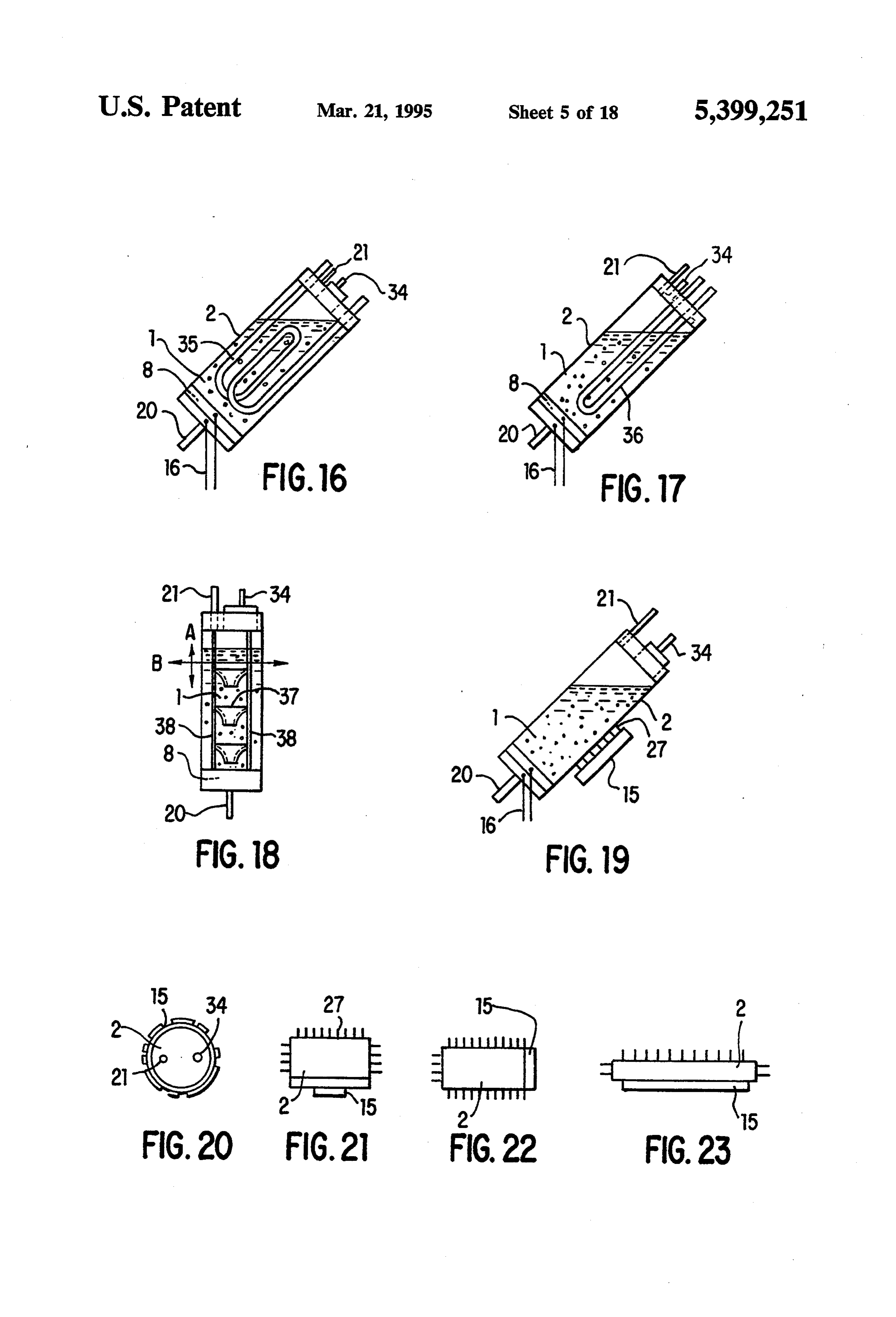
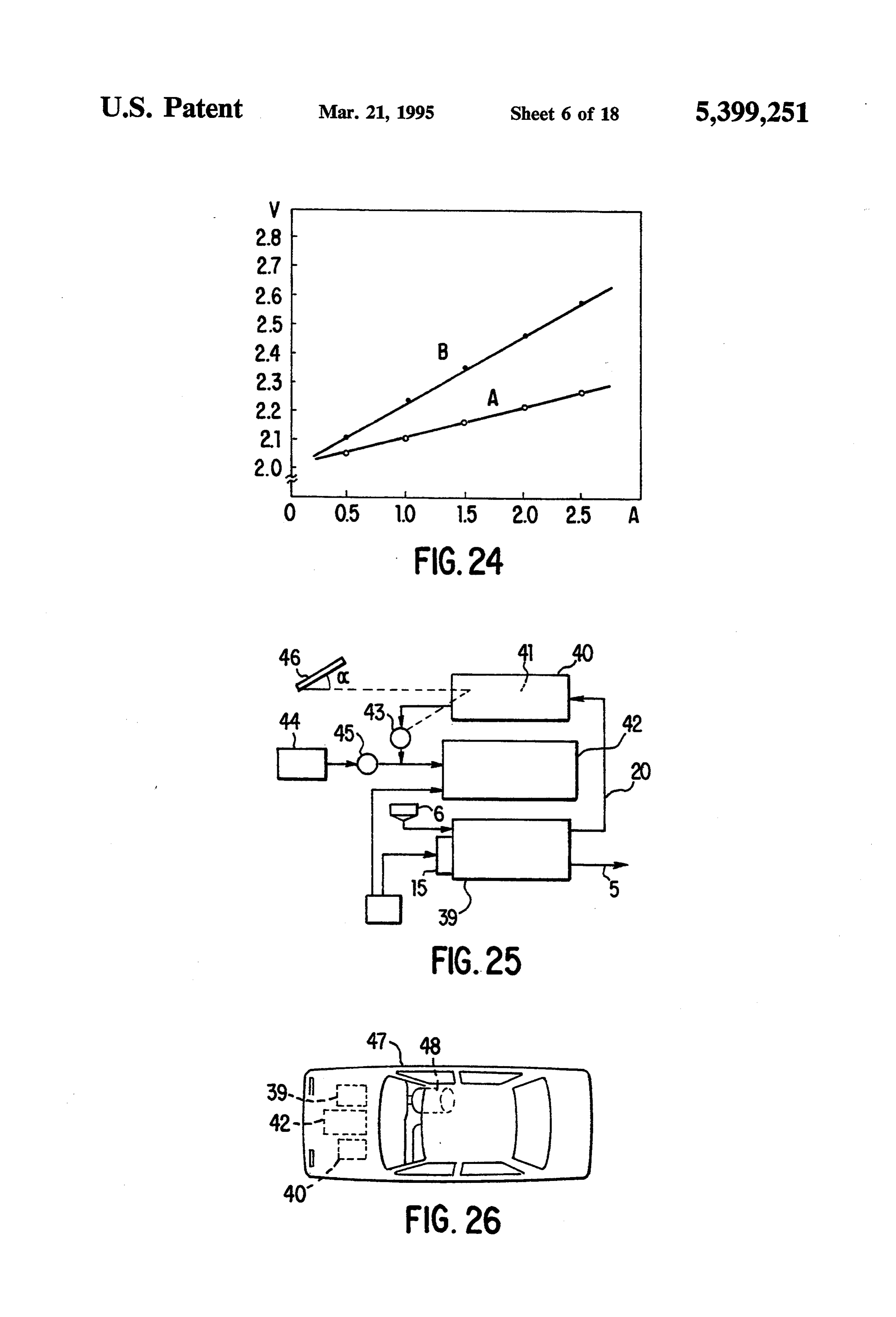
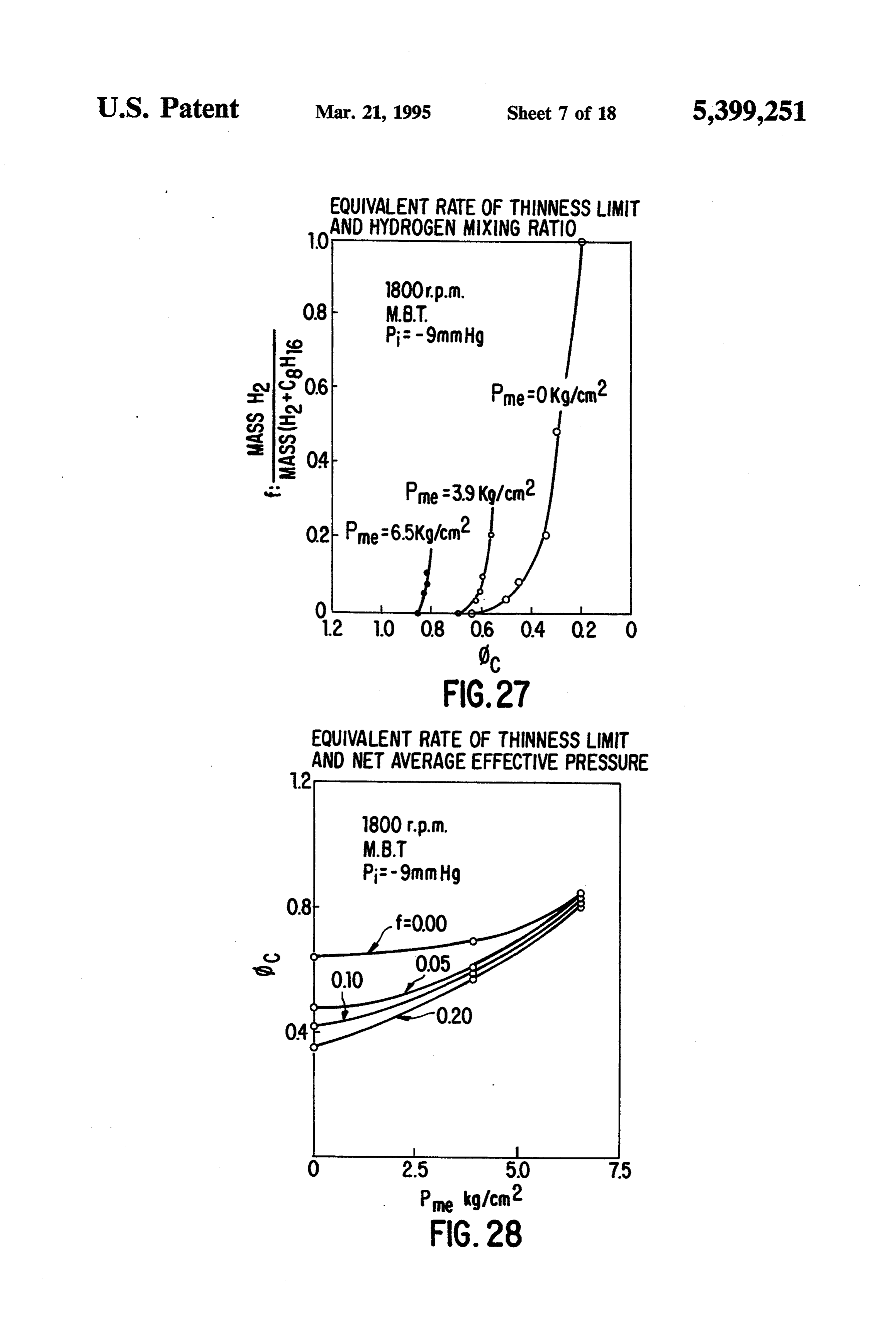
SYSTEM FOR GENERATING HYDROGEN AND BRIEF DESCRIPTION OF THE DRAWING OXYGEN In order that the invention may be more clearly un derstood, it will now be disclosed in greater detail with
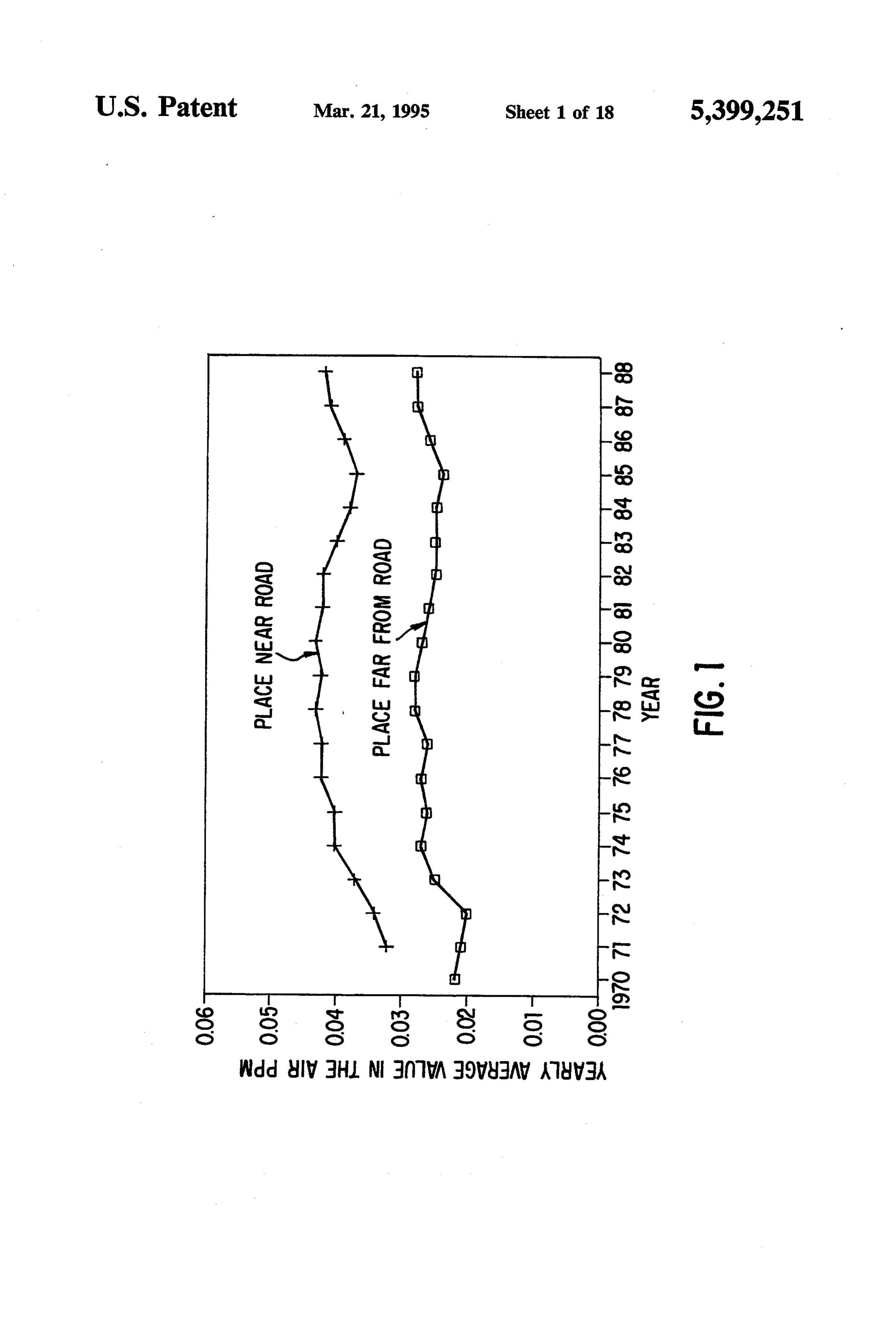
This application is a continuation of application Ser. 5 reference to the accompanying drawing, wherein: No. 07/602,187, filed Nov. 29, 1990, now abandoned. FIG. 1 is a graph showing the yearly change of nitro
FIELD OF THE INVENTION
gen dioxide in the air;
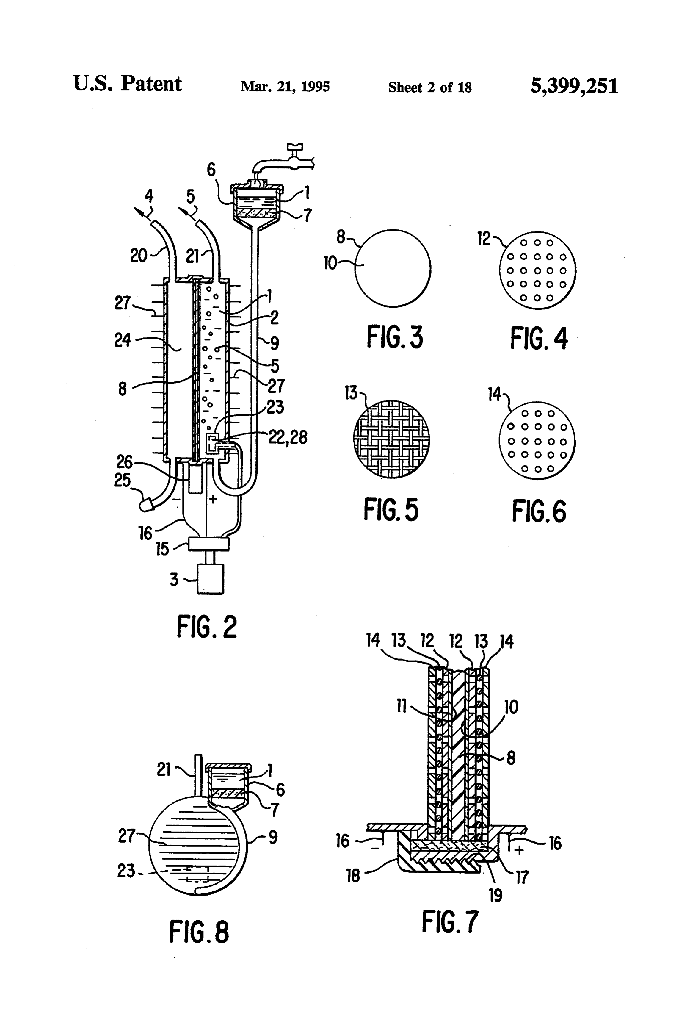
FIG. 2 shows a longitudinal section of example 1:
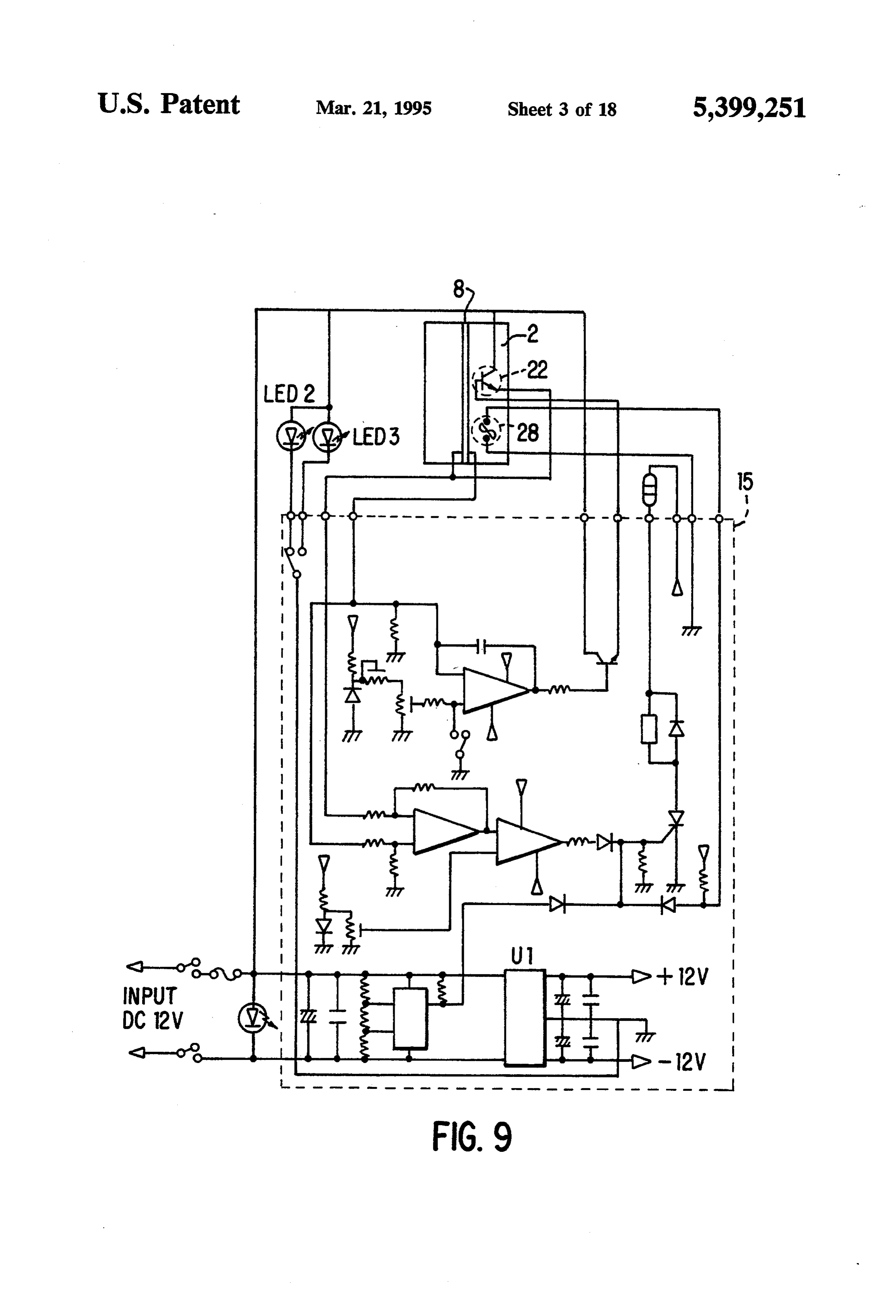
This invention relates to an energy system for electro FIG. 3 shows a side view of FIG. 2; lyzing water with high efficiency to generate hydrogen O FIG. 4 shows a side view of part of FIG. 2; and oxygen. Such hydrogen and oxygen may be em FIG. 5 shows a side view of part of FIG. 2; ployed, for example, as a fuel for powering automobiles, FIG. 6 shows an enlarged view of part of FIG. 2; ships, airplanes and rockets, and for generating electric FIG. 7 shows a side view of FIG. 2; ity. The system enables reduction of air pollution. FIG. 8 shows a side view of example 2; 15 FIG. 9 shows a circuit diagram of example 1;
BACKGROUND OF THE INVENTION FIG. 10 shows a longitudinal section of example 3; In Japan the number of automobile has sharply in FIG. 11 shows a side view of FIG. 10; creased due to the high growth of the economy, and air FIG. 12 shows a side cross section of example 4; pollution caused by automobile traffic has become a 20 FIG. 13 shows a side cross section of example 5; FIG. 14 shows a side cross section of example 6;
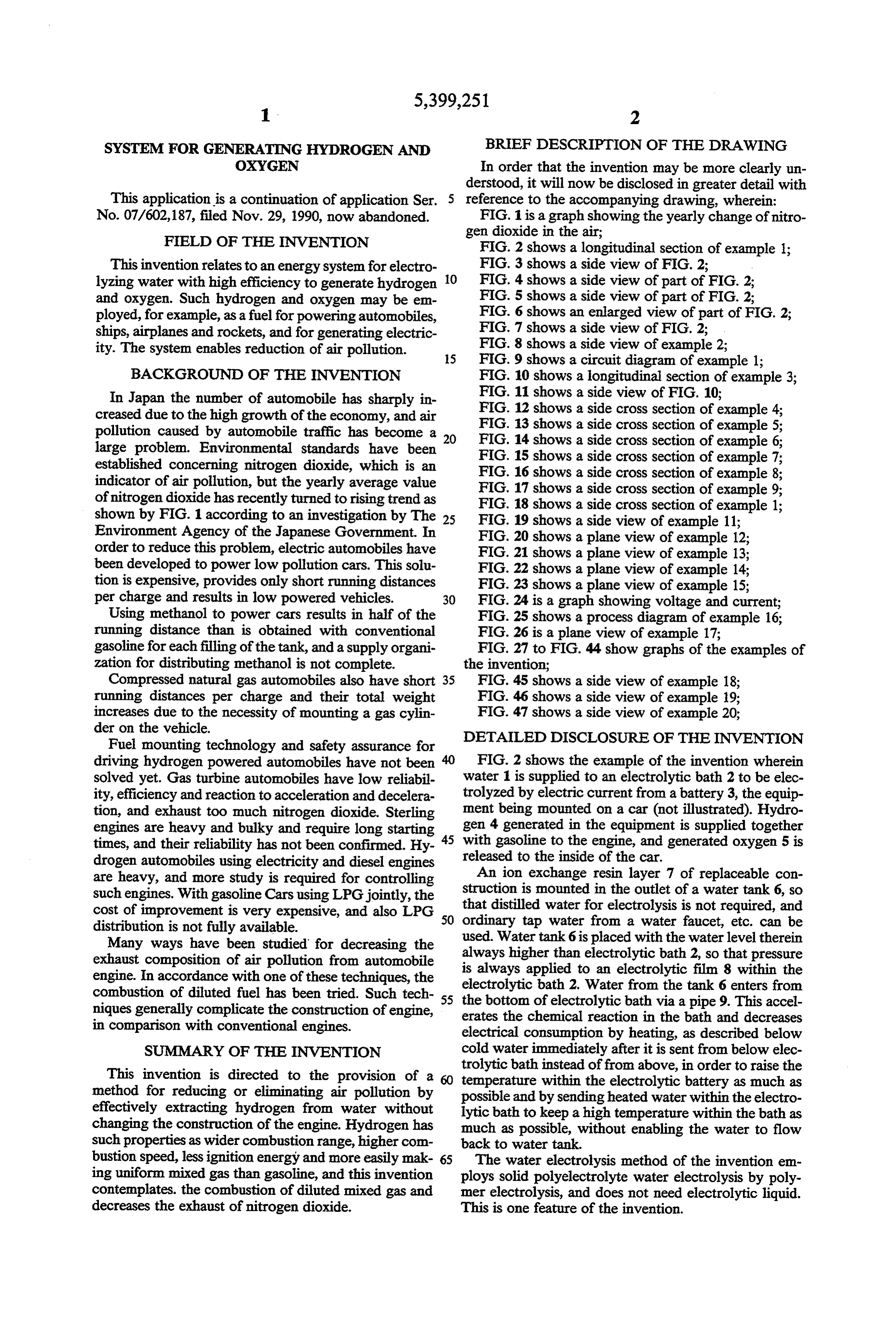
large problem. Environmental standards have been FIG. 15 shows a side cross section of example 7; established concerning nitrogen dioxide, which is an FIG. 16 shows a side cross section of example 8; indicator of air pollution, but the yearly average value FIG. 17 shows a side cross section of example 9; of nitrogen dioxide has recently turned to rising trend as FIG. 18 shows a side cross section of example l; shown by FIG. 1 according to an investigation by The 25 FIG. 19 shows a side view of example 11; Environment Agency of the Japanese Government. In FIG. 20 shows a plane view of example 12; order to reduce this problem, electric automobiles have FIG. 21 shows a plane view of example 13; been developed to power low pollution cars. This solu FIG.22 shows a plane view of example 14; tion is expensive, provides only short running distances FIG. 23 shows a plane view of example 15; per charge and results in low powered vehicles. 30 FIG. 24 is a graph showing voltage and current; Using methanol to power cars results in half of the FIG. 25 shows a process diagram of example 16; running distance than is obtained with conventional FIG. 26 is a plane view of example 17; gasoline for each filling of the tank, and a supply organi FIG. 27 to FIG. 44 show graphs of the examples of zation for distributing methanol is not complete. the invention;
Compressed natural gas automobiles also have short 35 FIG. 45 shows a side view of example 18; running distances per charge and their total weight FIG. 46 shows a side view of example 19; increases due to the necessity of mounting a gas cylin FIG. 47 shows a side view of example 20; der on the vehicle.
Fuel mounting technology and safety assurance for DETAILED DISCLOSURE OF THE INVENTION driving hydrogen powered automobiles have not been FIG. 2 shows the example of the invention wherein solved yet. Gas turbine automobiles have low reliabil water 1 is supplied to an electrolytic bath 2 to be elec ity, efficiency and reaction to acceleration and decelera trolyzed by electric current from a battery 3, the equip tion, and exhaust too much nitrogen dioxide. Sterling ment being mounted on a car (not illustrated). Hydro engines are heavy and bulky and require long starting gen 4 generated in the equipment is supplied together times, and their reliability has not been confirmed. Hy 45 with gasoline to the engine, and generated oxygen 5 is drogen automobiles using electricity and diesel engines released to the inside of the car. are heavy, and more study is required for controlling An ion exchange resin layer 7 of replaceable con struction is mounted in the outlet of a water tank 6, so such engines. With gasoline Cars using LPG jointly, the that cost of improvement is very expensive, and also LPG 50 distilled water for electrolysis is not required, and distribution is not fully available. ordinary tap water from a water faucet, etc. can be Many ways have been studied for decreasing the always used. Water tank 6 is placed with the water level therein exhaust composition of air pollution from automobile is always higher than electrolytic bath 2, so that pressure engine. In accordance with one of these techniques, the electrolyticapplied bath 2.
to an electrolytic film 8 within the
Water from the tank 6 enters from combustion of diluted fuel has been tried. Such tech 55 the bottom of electrolytic bath via a pipe 9. This accel niques generally complicate the construction of engine, erates the chemical reaction in the bath and decreases in comparison with conventional engines. electrical consumption by heating, as described below SUMMARY OF THE INVENTION cold water immediately after it is sent from below elec trolytic
This invention is directed to the provision of a temperature bath instead of from above, in order to raise the within the electrolytic battery as much as method for reducing or eliminating air pollution by possible and by sending heated water within the electro effectively extracting hydrogen from water without lytic bath to keep a high temperature within the bath as changing the construction of the engine. Hydrogen has much as possible, without enabling the water to flow such properties as wider combustion range, higher con back to water tank.
bustion speed, less ignition energy and more easily mak 65 The water electrolysis method of the invention em ing uniform mixed gas than gasoline, and this invention ploys solid polyelectrolyte water electrolysis by poly contemplates. the combustion of diluted mixed gas and mer electrolysis, and does not need electrolytic liquid. decreases the exhaust of nitrogen dioxide. This is one feature of the invention.
Page 21
As shown in FIG. 2, 3, 4, 5, 6 and 7 and also as de 20 mm diameter electrolytic film, hydrogen was gener scribed below, the electrolytic film in the electrolytic ated at 12.59 cc/minute with a voltage of 12 V and bath 2 is a solid polyelectrolytic film 8 having a positive current of 2.5A; hydrogen was generated at 9.98 cc/mi electrode 10 on one side and a negative electrode 11 on nute with a voltage of 12V and current of 2.0 A; hydro the other side. The solid polyelectrolytic film 8 extends 5 gen was generated at 7.53 cc/minute at a voltage of 12 vertically and is sandwiched with apertured metal V and current of 1.5 A, hydrogen was generated at 5.00 plates 12, metal nets 13 and another apertured metal cc/minute at a voltage of 12V and current of 1.0 A; and plates 14 symmetrically arranged on both sides offilm 8. hydrogen was generated at 2.42 cc/minute at a voltage The solid polyelectrolytic film 8 is mounted to extend of 12 V and current of 0.5 A.
vertically in order to enable it to vibrate as the car or 10 In order to heat water within the electrolytic bath 2 other vehicle is moved in order to easily set hydrogen shown in FIG. 2, a heat generating element 22 such as foam free, to thereby accelerate the chemical reaction, a rectifier, transistor, etc. in the circuit of the power to enhance the efficiency of heating from the outside of the electrolytic bath and the efficiency of heating up supply 15 shown by FIG.9, is coated with Teflon resin or sealed in titanium box 23, and mounted within the interior heat generating substance by making the elec 15 electrolytic bath 2. This arrangementis designed to heat trolytic film thinner, not to prevent hydrogen and oxy water at the location of electrolysis and to simulta gen from rising, and also to simplify the drain on the neously cool the heat generating parts of the power side of positive electrode. Electricity is applied to elec supply circuit. Especially when the electrolytic bath is trodes 10, 11 of said film 8 from power supply 15 con made of plastics without using heat absorbing fins, as set nected to battery 3 via electric cables 16.
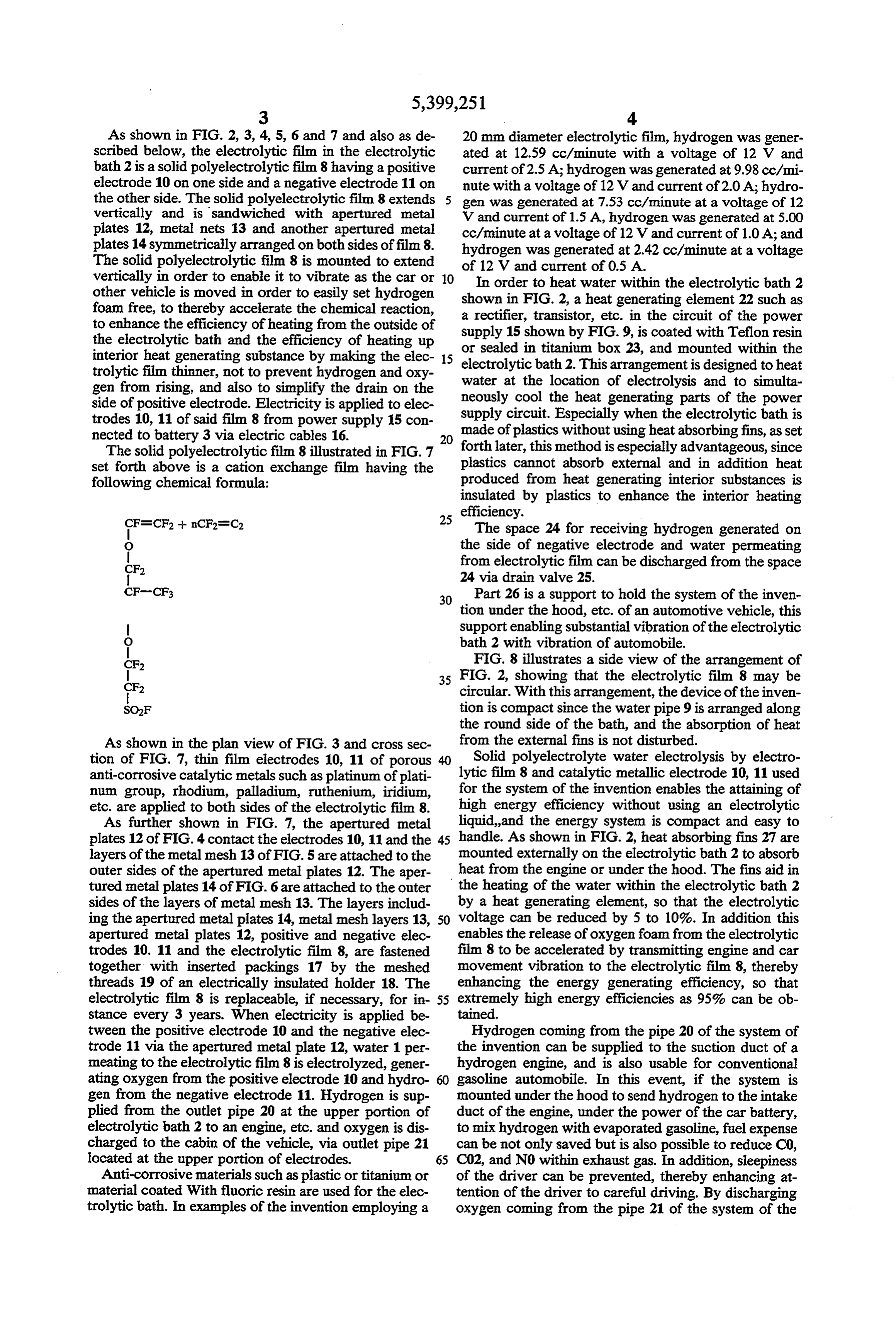
The solid polyelectrolytic film 8 illustrated in FIG. 7 forth later, this method is especially advantageous, since set forth above is a cation exchange film having the plastics cannot absorb external and in addition heat following chemical formula: produced from heat generating interior substances is insulated by plastics to enhance the interior heating
efficiency.
The space 24 for receiving hydrogen generated on
O the side of negative electrode and water permeating CF2 from electrolytic film can be discharged from the space 24 via drain valve 25.
30 Part 26 is a support to hold the system of the inven tion under the hood, etc. of an automotive vehicle, this support enabling substantial vibration of the electrolytic
O bath 2 with vibration of automobile. FIG. 8 illustrates a side view of the arrangement of
35 FIG. 2, showing that the electrolytic film 8 may be circular. With this arrangement, the device of the inven tion is compact since the water pipe 9 is arranged along the round side of the bath, and the absorption of heat
As shown in the plan view of FIG. 3 and cross sec from the external fins is not disturbed. tion of FIG. 7, thin film electrodes 10, 11 of porous Solid polyelectrolyte water electrolysis by electro anti-corrosive catalytic metals such as platinum of plati lytic film 8 and catalytic metallic electrode 10, 11 used num group, rhodium, palladium, ruthenium, iridium, for the system of the invention enables the attaining of etc. are applied to both sides of the electrolytic film 8. high energy efficiency without using an electrolytic As further shown in FIG. 7, the apertured metal liquid, and the energy system is compact and easy to plates 12 of FIG. 4 contact the electrodes 10, 11 and the 45 handle. As shown in FIG. 2, heat absorbing fins 27 are layers of the metal mesh 13 of FIG. 5 are attached to the mounted externally on the electrolytic bath 2 to absorb outer sides of the apertured metal plates 12. The aper heat from the engine or under the hood. The fins aid in tured metal plates 14 of FIG. 6 are attached to the outer the heating of the water within the electrolytic bath 2 sides of the layers of metal mesh 13. The layers includ by a heat generating element, so that the electrolytic ing the apertured metal plates 14, metal mesh layers 13, 50 voltage can be reduced by 5 to 10%. In addition this apertured metal plates 12, positive and negative elec enables the release of oxygen foam from the electrolytic trodes 10. 11 and the electrolytic film 8, are fastened film 8 to be accelerated by transmitting engine and car together with inserted packings 17 by the meshed movement vibration to the electrolytic film 8, thereby threads 19 of an electrically insulated holder 18. The enhancing the energy generating efficiency, so that electrolytic film 8 is replaceable, if necessary, for in 55 extremely high energy efficiencies as 95% can be ob stance every 3 years. When electricity is applied be tained.
tween the positive electrode 10 and the negative elec Hydrogen coming from the pipe 20 of the system of trode 11 via the apertured metal plate 12, water 1 per the invention can be supplied to the suction duct of a meating to the electrolytic film 8 is electrolyzed, gener hydrogen engine, and is also usable for conventional ating oxygen from the positive electrode 10 and hydro 60 gasoline automobile. In this event, if the system is gen from the negative electrode 11. Hydrogen is sup mounted under the hood to send hydrogen to the intake plied from the outlet pipe 20 at the upper portion of duct of the engine, under the power of the car battery, electrolytic bath 2 to an engine, etc. and oxygen is dis to mix hydrogen with evaporated gasoline, fuel expense charged to the cabin of the vehicle, via outlet pipe 21 can be not only saved but is also possible to reduce C0, located at the upper portion of electrodes. 65 C02, and NO within exhaust gas. In addition, sleepiness Anti-corrosive materials such as plastic or titanium or of the driver can be prevented, thereby enhancing at material coated With fluoric resin are used for the elec tention of the driver to careful driving. By discharging trolytic bath. In examples of the invention employing a oxygen coming from the pipe 21 of the system of the
Page 22
invention to the drivers seatin order to provide oxygen heat generating volume from 0.0899 kg/m3 (gas) of to the brain of driver. hydrogen's density and 0.74 kg/l (liquid) of gasoline's The circuit of FIG. 9, is an example of the circuit of density, hydrogen is 28,800X 0.0899=2,589 kcal/m3 the power supply 15 for supplying constant current (H2 gas) and gasoline 10,500x0.74=7,770 kcal/m3 from the battery 3 to the electrolytic bath 2. The battery 5 (gasoline). Consequently the supply volume of hydro of the automobile is usable for supplying the input to gen and gasoline is 2,655/2,589/60=17.1 1/min and this circuit, for example a battery having a capacity of 1,841.5/7,770/60=39.5 cc/min respectively. 12 VDC at 5 A can be used, and the range of input Assuming that one sheet of electrolytic film with a 8 voltages for the circuit is 10-15 V. cm diameter generates 50 cc/min of hydrogen, 342 The output of the circuit of FIG. 9 is set with range 10 sheets of the film aligned in parallel are required to of 0 VDC, 4 A. Lamp LED 2 is lit to shut off the output supply 17.1 l/min of hydrogen to a conventional auto current when the output voltage exceeds DC 2.8 V by mobile engine. However, as shown in FIG. 22, in the increasing of the resistance resulting from long usage of system of the invention using a hydrogen tank 31, the the solid polyelectrolytic film, or when the input volt number of electrolytic films as set forth above is not age has fallen to lower than DC 10 V due to consump 15 required, since controller 32 controls the necessary tion of the battery and the temperature of radiator ex volume of hydrogen according to the condition of the ceeds 80 degrees C. Lamp LED 3 is lit when output engine and because, as long as the controller 32 works, current is supplied. hydrogen is stored in the tank to be released only when Part U-1 in the power supply circuit is a DC/DC necessary.
converter to provide an output voltage of -12V neces 20 FIG. 13 shows an example of the invention wherein a sary to drive the op-amp. plurality of electrolytic baths are connected to a unit 31. Part 28 of the circuit is a thermal fuse which senses FIG. 14 shows an example of the invention wherein the temperature in the bath to shut off the output cur the electrolytic bath 2 is cylindrical with the electro rent when the temperature of element 22 rises to more lytic film 8 attached to its bottom. Vibration of car than 80 degrees C. 25 moves water within the electrolytic bath 2 in a vertical Element 22 in the circuit is a transistor having large direction A, and power in the A direction is divided heat generation. The invention serves the double pur into the B direction axial of the electrolytic bath 2 and pose of enhancing electrolytic efficiency to lower the in the C direction at right angles to the axis of the elec voltage by raising the water temperature within electro trolytic bath 2 and also in parallel with the surface of lytic bath 2 by using the heating property of element 22, 30 the electrolytic film 8, in order to accelerate discharg as shown by FIG. 2, and also of cooling the transistor or ing foam of hydrogen coming from electrolytic film 8 to other element 22 at the same time. enhance electrolytic efficiency. Heat absorbing fins 27, As shown in FIG. 19, it is also possible to heat the drain pipe 32, fixture 33, water inlet 34, ion exchange water by attaching radiation fins 27 to the transistor and resin layer 7, hydrogen outlet 20 and oxygen outlet 21 contacting the radiation fins with the metallic electro 35 are mounted in the electrolytic bath 2. lytic bath 2 made of such metals as titanium, etc. It is FIG. 15 shows an example of the invention wherein also possible to heat the water by contacting the radia the electrolytic bath 2 is inclined and the bottom of tion fins with the outside of electrolytic bath 2 made of electrolytic bath extends vertically. In this arrangement such metals as titanium, etc. the water inlet is in an upper horizontal portion of elec FIG. 10 and FIG. 11 show an example of the inven 40 trolytic bath. The ion exchange resin layer and the tion wherein heat absorbing fins 27 are mounted to electrolytic film are represented by the reference nu extend in the direction of the diameter of electrolytic merals 7 and 8 respectively. The electrolytic bath is bath 2, and water pipe 9 is inserted between the heat made of non-corrosive metals such as titanium, etc. and absorbing fins 27 so as to place the heat absorbing fins heated semi-conductors in the power supply circuit 27 on the water pipe 9 itself in order to preheat the 45 contact the outside of electrolytic bath so that the heat water before it enters the electrolytic bath. of engine, etc. is transmitted through fins 27 to heat the FIG. 12 shows an example of the invention wherein a electrolytic bath.
plurality of electrolytic films 8 are aligned in parallel to FIG. 16 is an example of the invention wherein the increase the generation of hydrogen. This reason for the electrolytic bath, etc. are heated. Using the example of use of a plurality of electrolytic films is explained in the 50 FIG. 14, heating pipe 35 is installed in the cylindrical following paragraphs. electrolytic bath 2 to heat the water 1 by sending heat of Gasoline is represented by the formula C8H16 and if the engine and exhaust into heating pipe 35 in order to the hydrogen mixing rate is 5%, the volume of hydro enhance the electrolytic efficiency.
gen to 1 mol (112 g) of gasoline is 112X0.05/ FIG. 17 shows an example of the invention wherein (1-0.05)=5.89 g. 55 an electric heating wire 36 coated with Teflon resin is Since the heat generating volume at low mixtures of placed within the electrolytic bath 2 to heat water 1 by hydrogen and gasoline is 10,500 kcal/kg and 28,800 current from the automobile battery.
kcl/kg respectively, when a 5% hydrogen mixing rate is FIG. 18 is an example of the invention using a verti converted to heat generating volume, hydrogen be cally extending tube shown in FIG. 14, wherein mem comes 5.89x28.8/ (5.89x28.8-112X 10.5);=12.6%. bers 37 in the shape of trumpet horns are supported by Considering a 30% heat efficiency of the engine and rods 38 inserted in the water tank 1. Motion A of the approximately 10 horsepower under light load (40 to 50 water in a vertical direction due to up and down move km/h of constant speed on city roads), heat input at 10 ment of car is converted to movement in the horizontal horsepowers (7.35 kw) of net output is 7.35/0.3=24.5 direction B to improve discharging and dispersing foam kw=24.5x860 kcal/h =21,070 kcal/h. 65 of the hydrogen gas.
The supply calorie of hydrogen out of the 21,070 FIG. 19 is an example of the invention wherein radi kcal/h is 0.126x21,070=2,655 kcal/h and that of gaso ating fins 27 of the power supply 15 are attached along line is 21,070-2,655=18,415 kcl/h. When obtaining the outside wall of the electrolytic bath 2 to heat the
Page 23
water within the electrolytic bath 2 by heat generated The hydrogen storage alloy filed storage tank 40 is from the power supply and also to cool the heat gener placed close to the engine to discharge hydrogen from ating semi-conductors. the metal by heat coming from engine 42. This hydro FIG. 20 is an example of the invention wherein the gen tank 40 is connected to the hydrogen controller 42 power supply 15 is fabricated on a flexible printed cir 5 which is designed to shut down hydrogen when the cuit board which is mounted around the electrolytic load to engine becomes large. In other words, the con bath 2 to heat water within the bath and cool the power troller 43 is closed and the supply of hydrogen to the supply circuit. engine stops or is reduced, during which period hydro FIG. 21 is an example of the invention wherein the gen from the hydrogen generating apparatus is stored in power supply 15 is fixed on the wide bottom of the 10 the hydrogen tank. The controller, when necessary, electrolytic bath 2 in the form of a cube and heat ab opens to send hydrogen to the engine. Therefore, in sorbing fins 27 are attached to other surfaces, so that the accordance with the invention, even a small hydrogen electrolytic efficiency can be enhanced by heat gener generating capacity is enough to drive the engine, so ated by the power supply and heat absorbed by fins 27 that the system may be small. A hydrogen cylinder can from the engine. 15 be used instead of the hydrogen tank 31, or can be used FIG. 22 is an example of the invention wherein the along with the hydrogen tank 31.
power supply 15 is mounted on a narrow longitudinal The controller 43 changes the volume of hydrogen in face of the electrolytic bath in the form of a rectangular proportion to the size of the load, the density of mixed parallel piped, as shown in the previous example. gas and the size of mixing ratio. FIG. 23 shows an example of the invention wherein 20 FIG. 26 is a plane figure showing an automobile 47 the electrolytic bath 2 is very thin, so that the tempera incorporating the system of the invention, and also ture of interior water is easy to raise by external heating, illustrating the driver 48.
and the power supply 15 is set on the widebottom of the In order to describe the hydrogen controller 43, the electrolytic bath 2. test data of the example of the invention, FIG. 27 graph FIG. 24 shows the test results of the inventor, assum 25 ically shows the relationship between the equivalent ing that the abscissa and ordinate represent the neces ratio of limit of hydrogen thinness d and the hydrogen sary current and voltage and current, respectively, for mixing rate f.
electrolysis, and the curve B shows the relationship Hydrogen generated by this system was sent into an between the voltage and current when neither heat nor inlet pipe located at approximately 50 mm down from vibration is provided. Curve A shows the relationship 30 the throttle valve within the pipe or suction pipe lo in accordance with the invention upon the application cated at approximately 150 mm up from carburetor. of loading pressure on the electrolytic film 8 by heating The stroke capacity of engine used for this experiment and vibrating water 1 within electrolytic bath 2. This is 323 cc.
test shows that the voltage necessary for electrolysis is The equivalent ratio d of hydrogen is represented by reduced by at least 15% and the energy efficiency is 35 the ratio of quality and volume of oxygen necessary for consequently enhanced. complete combustion of mixed gas consisting of hydro FIG. 25 shows an example of the invention com gen and gasoline with respect to the quality and volume prised of 3 main elements of the hydrogen generating of oxygen within the mixed gas. The hydrogen mixing apparatus, hydrogen storing apparatus and controller rate f is represented by comparison of quality and vol which have been explained with reference to FIG. 2. 40 ume of hydrogen with quality of volume of hydrogen The hydrogen outlet pipe 20 from the electrolytic plus gasoline.
hydrogen generating apparatus 39 driven by the battery As clearly apparent from FIG. 27, the effect of driv 3 and the power supply 15 of FIG. 2 are connected to ing capacity of thin fuel increases at lower hydrogen the hydrogen tank 40, where a hydrogen storage alloy mixing rates and also at lower loads.
41, such as iron plus titanium or iron plus titanium plus 45 FIG. 28 shows that a thicker mixed gas is required as niobium, invented by me, is filled to efficiently absorb hydrogen in the system increases together with in hydrogen. As I have explained in another of my patent creases of load.
applications, an alloy of iron and titanium and Niobium Gasoline engines can be driven only by thin mixed has a hydrogen storage capacity of 6.7 times as much as gas of not more than approximately 1.2 times as much as a conventional hydrogen cylinder. A controller 43 for 50 generally theoretical gas volume. Therefore the output controlling the hydrogen volume is set between this at low driving speed is controlled by throttling the hydrogen tank 40 and the engine 42. Gasoline 44 is volume of both the fuel and air. However, since the supplied to the engine 42 via and evaporator 45. FIG.25 driving limit of thin mixed gas is expanded when adding also shows the system where hydrogen is supplied from hydrogen by this system, it is possible to control the the controller 43. 55 output by decreasing only the volume of fuel without The hydrogen controller 42 is designed to increase throttling air, to decrease any damage to the pump by and decrease the supplied volume of hydrogen as a throttling the volume of sucked air and to enhance the function of the rpm of the engine or the angle (alpha) of heat efficiency, i.e. one of effects of the present inven the accelerator pedal 46. tion.
The hydrogen generating apparatus 39 receives heat 60 This effect becomes more remarkable with lower produced by the engine or exhaust from the engine or output of driving with thin mixing ratio, and also the from a supply of electricity to heat the generating parts addition of hydrogen when driving with thin mixed gas 22 of the power source and electrolytic film 8, and makes it possible to decrease the combustibility of hy produces hydrogen to be stored in the hydrogen storage drocarbon HC, CO, etc. On the other hand, when driv alloy filled hydrogen tank 40. The hydrogen storage 65 ing with a thick mixed gas near the theoretical mixing alloy in the hydrogen tank is cooled by water 1 in order ratio (high output driving), the effect of the addition of to send hydrogen to hydrogen tank by pressure for hydrogen is lower, and when increasing the mixing storage. ratio of hydrogen, the output adversely lowers, leading
Page 24
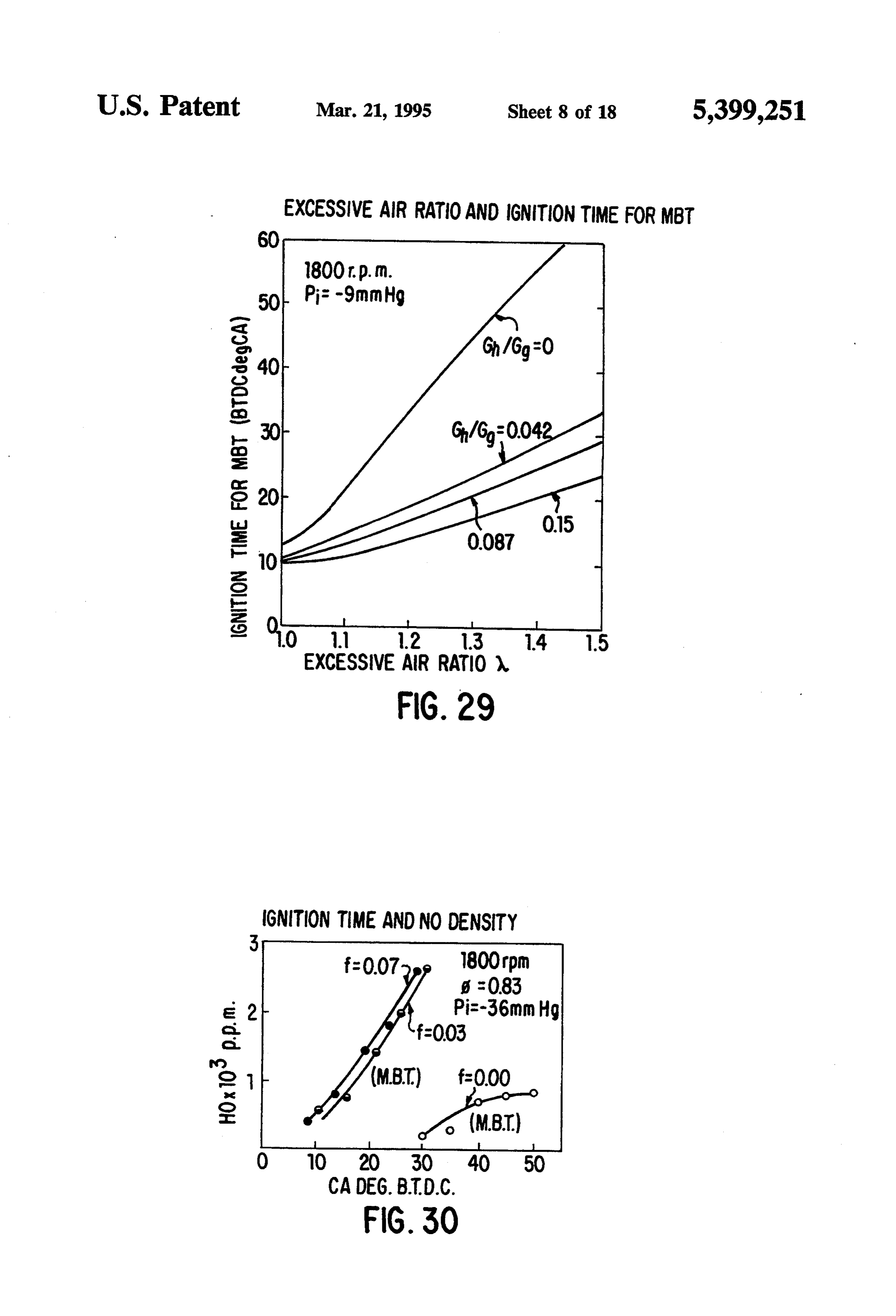
to increase in exhaust of NOx. Consequently, the addi effect of hydrogen having a high combustion speed, but tion of hydrogen is recommended for partial load driv also to the effect as set forth above. ing, and driving with gasoline only is better for high The effect of the invention on the density of air pollu load driving. tion materials contained in engine exhaust results in Consequently, as explained with reference to FIG. making possible the driving of cars at fully low equiva 25, I have provided a system having a hydrogen con lent rate of NO density compared with gasoline, only by troller 43. mixing hydrogen into thin mixed gas. The effect of mixing hydrogen into the fuel when FIG. 29 shows the measurement of ignition time for driving with a thin gas mixture is especially effective, MBT when driving by adding hydrogen to gasoline, and the preferred hydrogen mixing rate is 5 to 10%. 10 and it is indicated that the ignition time for MBT is The smaller that the flame speed is when using a thin greatly delayed by adding a small amount of hydrogen. mixed gas of gasoline and air, the more effective flame FIG. 30 shows the effect on NO density when chang transmission is accelerated by mixing small hydrogen ing the ignition timing at constant rotation speed and with the fuel, for which the present controller is effec equivalent rate by 5 degrees and 10 degrees before and tive. 15 after from MBT, and the effect of the invention wherein When using gasoline only, the ignition advance angle, it is possible on lowering NO density by delaying the which is referred to herein as the MBT (Minimum Ad ignition timing.
vance for Best Torque) increases in proportion to the FIG. 31 shows the relationship between NO density rotating speed of the engine, but the degree is reduced and decreasing rate of average effective pressure ac by mixing hydrogen with the fuel. It has been found by 20 cording to ignition delaying angle from MBT, and it experiment that in the case of a high speed rotation indicates the effect wherein mixing hydrogen in accor there is a trend that the effect of mixing hydrogen is dance with the invention has a large effect on lowering large until the hydrogen mixing rate is large. NO density compared with the output decrease by igni If gasoline in a thin mixed gas at constant equivalent tion delaying angle. Furthermore, it is the effect of the ratio continues to be partially replaced with hydrogen, 25 invention that, when using thinner mixed gas, mixed it is possible to delay the ignition time for MBT, and the hydrogen is also advantageous in the NO exhausting output increases when the hydrogen mixing rate is rate (g/ps.h).
small. FIG. 32 shows that the NO exhaust rate is decreased When maintaining a constant rotation speed, it is by increase in the value of Gh/Gg. Compared with possible to make the equivalent ratio substantially 30 driving with gasoline of A= 1.0, when driving with smaller under no-load conditions, hardly changing the A=1.3 and adding hydrogen, the NO exhaust rate is ignition time for MBT together with increasing hydro decreased to approximately .
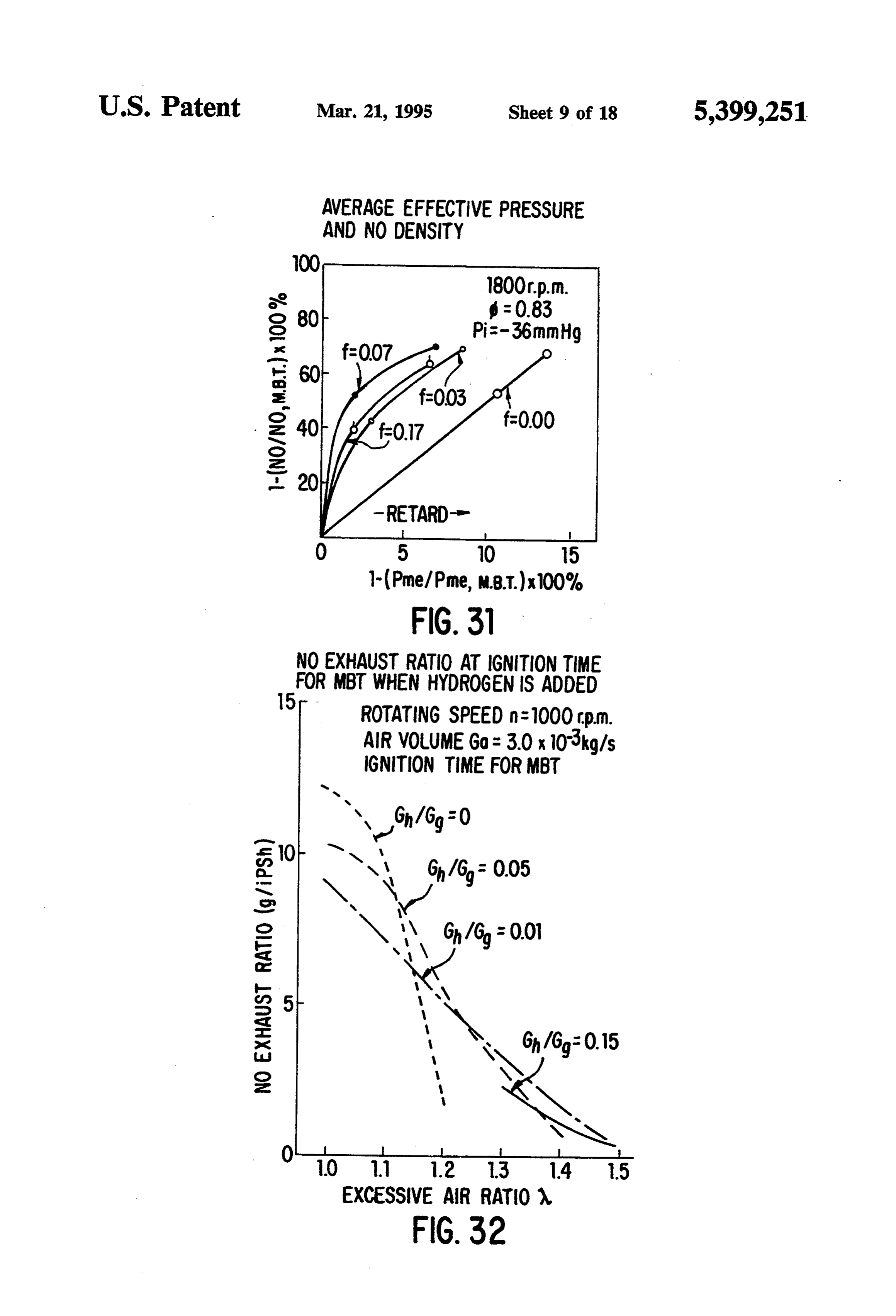
gen mixing ratio. With mixed gas required by the out FIG. 33 shows the indicated horsepower of ignition put, the smaller its equivalent rate is, the larger the timing, HC within the exhaust gas, CO and the effect on hydrogen mixing effect is. 35 NO exhaustrate. The HC exhaustrate become less with If hydrogen is mixed with mixed gas of gasoline and increases in the added volume of hydrogen, and it air, combustion speed increases and the relationship of slightly increases when delaying ignition time. the hydrogen mixing rate with combustion speed shows The reason that HC exhaust is decreased by adding an almost straight tendency. For instance, the regular hydrogen is that the flowing volume of gasoline de combustion speed of thin mixed gas having a 0.7 equiva creases by adding the volume of hydrogen, inasmuch as lent rate at a hydrogen mixing rate of 0.2% and 10% is the excessive air ratio A is kept at constant level, and 20.25 cm/s and 40 cm/s respectively, having an almost that combustion efficiency around the wall of combus straight relationship. The effect of mixing hydrogen on tion chamber is accelerated since the hydrogen's lame the combustion speed is more remarkable as the mixing distinguishing distance becomes small at the same time rate becomes smaller, showing a logarithmic change 45 as the rise of maximum pressure. (see FIG. 42.) with the mixing rate. The C0 exhaust rate also shows a similar tendency as Hydrogen mixing accelerates the effect of increasing the HC exhaust rate but is hardly dependable on igni combustion speed, particularly by turbulence of thin tion time. The NO exhaust rate sharply decreases when mixed gas. Increase of combustion speed in turbulent delaying the ignition time. The NO exhaust rate at the flow by mixing hydrogen on the side of excessive den 50 same ignition time increases as the value of Gh/Gig sity of hydrogen having approximately 1.3 of equivalent increases, since the combustion speed increases by add ratio db shows an almost straight relationship as well as ing hydrogen and the temperature of combustion of the an increase in regular combustion speed, and hydrogen gas increases.
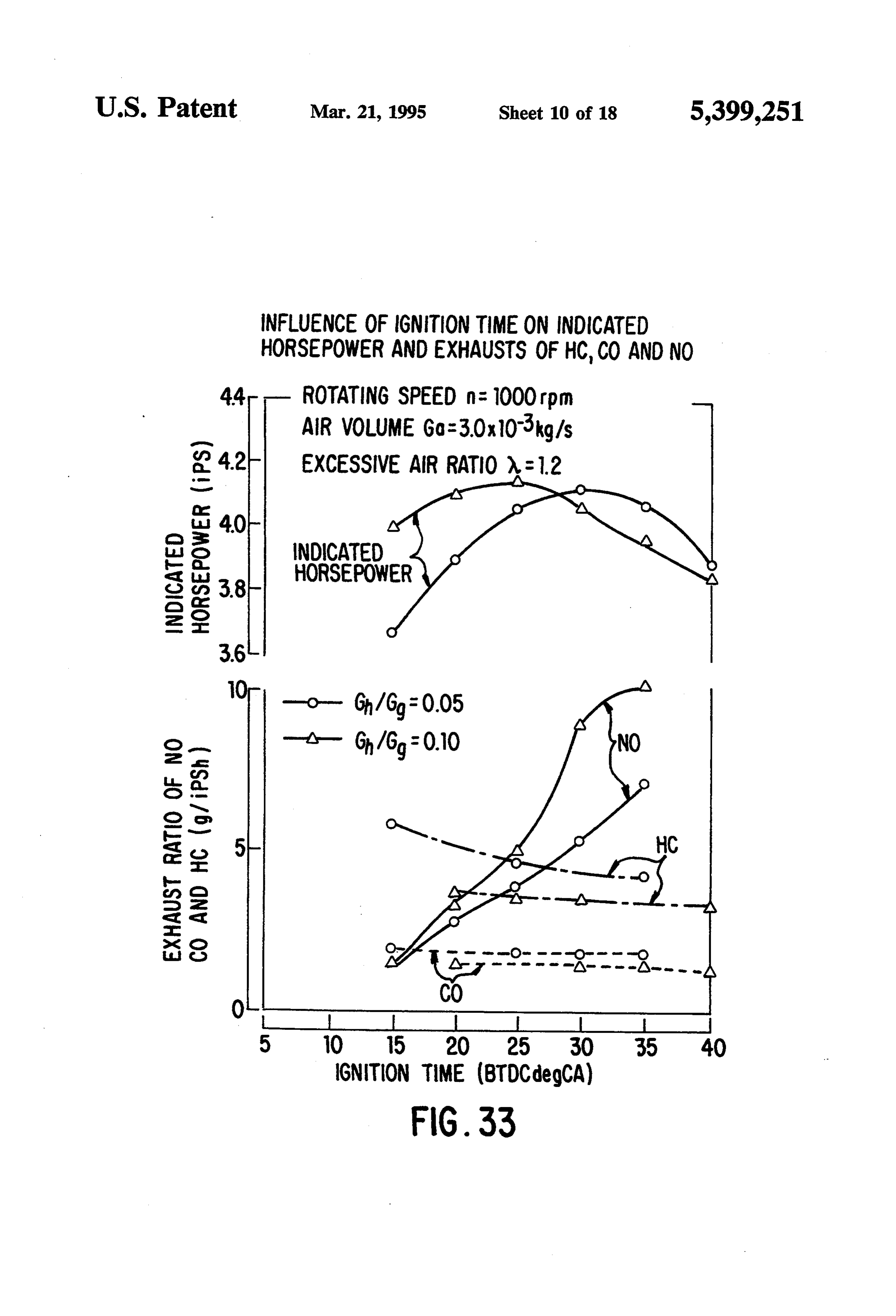
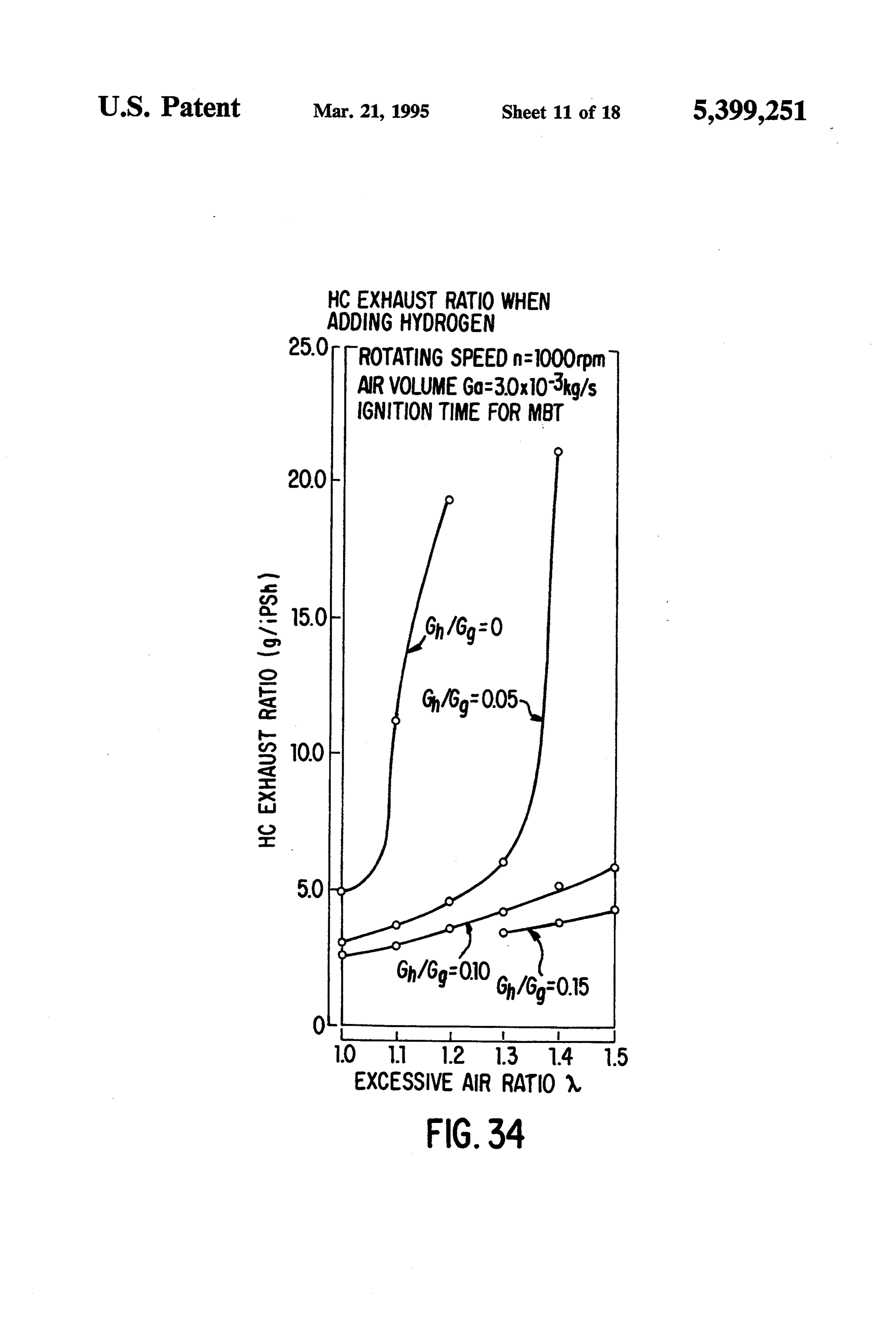
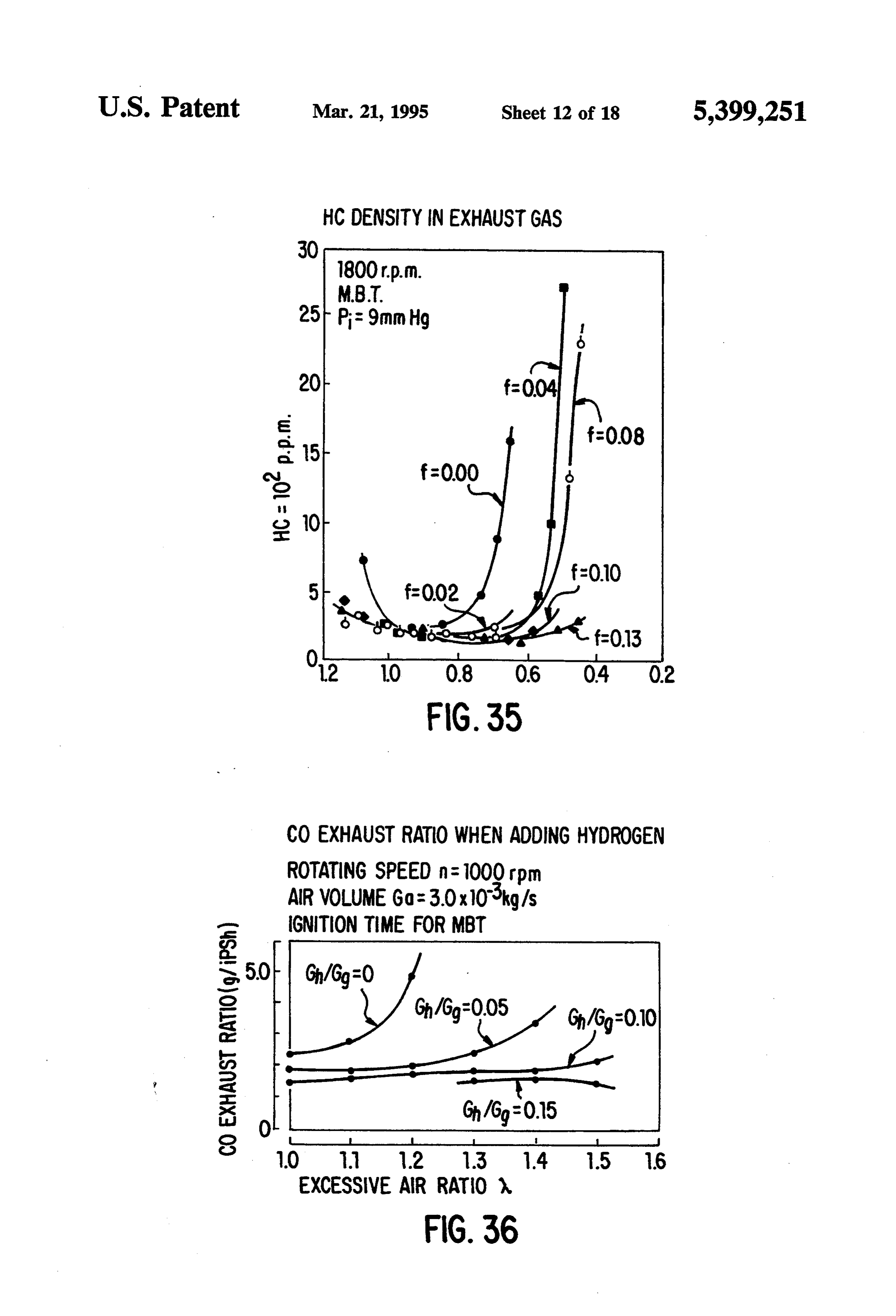
combustion speed on the side of thin density of hydro FIG. 34 shows the fluctuation of the HC exhaustratio gen increases greatly by mixing approximately 2% hy 55 when changing the excessive air ratio. When approach drogen. The reason why the effect of turbulence on ing the condition of discontinuing combustion, the HC combustion speed increases greatly on the side of thin exhaust ratio’is seen to sharply increase. When the ex density by adding small amount of hydrogen is that the cessive air ratio is increased, there is trend for the HC molecule dispersion coefficient of hydrogen is so ex exhaust ratio to increase, but it is possible to protect the tremely large that hydrogen disperses on the surface of 60 increase in HC exhaust by increasing the Gh/Gig value. irregular disordered combustion and selects oxygen to FIG. 35 shows the effect of changes in HC density burn. On the basis of observations when using a burning within the exhaust by the equivalent ratio, using the vessel, it has been confirmed that the irregular surface hydrogen mixing rate of the invention as a parameter, offlame becomes very fine by mixing hydrogen. Conse and it indicates the effect of the invention that it is possi quently, when using this mixed gas, effective transmis 65 ble to control the increase in HC density until the thin sion of flame is accelerated more and more in case of side of mixed gas by mixing hydrogen according to the thin mixed gas and of lower mixing ratio of hydrogen. invention. This figure shows the effect of the invention Delaying MBT ignition timing is due to not only the that, when thin mixed gas having equivalent ratio d of
Page 25
approximately 0.75, HC density and HC exhaust rate substantially decreased by mixing hydrogen in accor provided the heat generating amount of hydrogen dance with the invention. added by the invention and gasoline per unit of volume FIG. 36 shows the CO exhaust rate when adding aregh and gg, respectively.
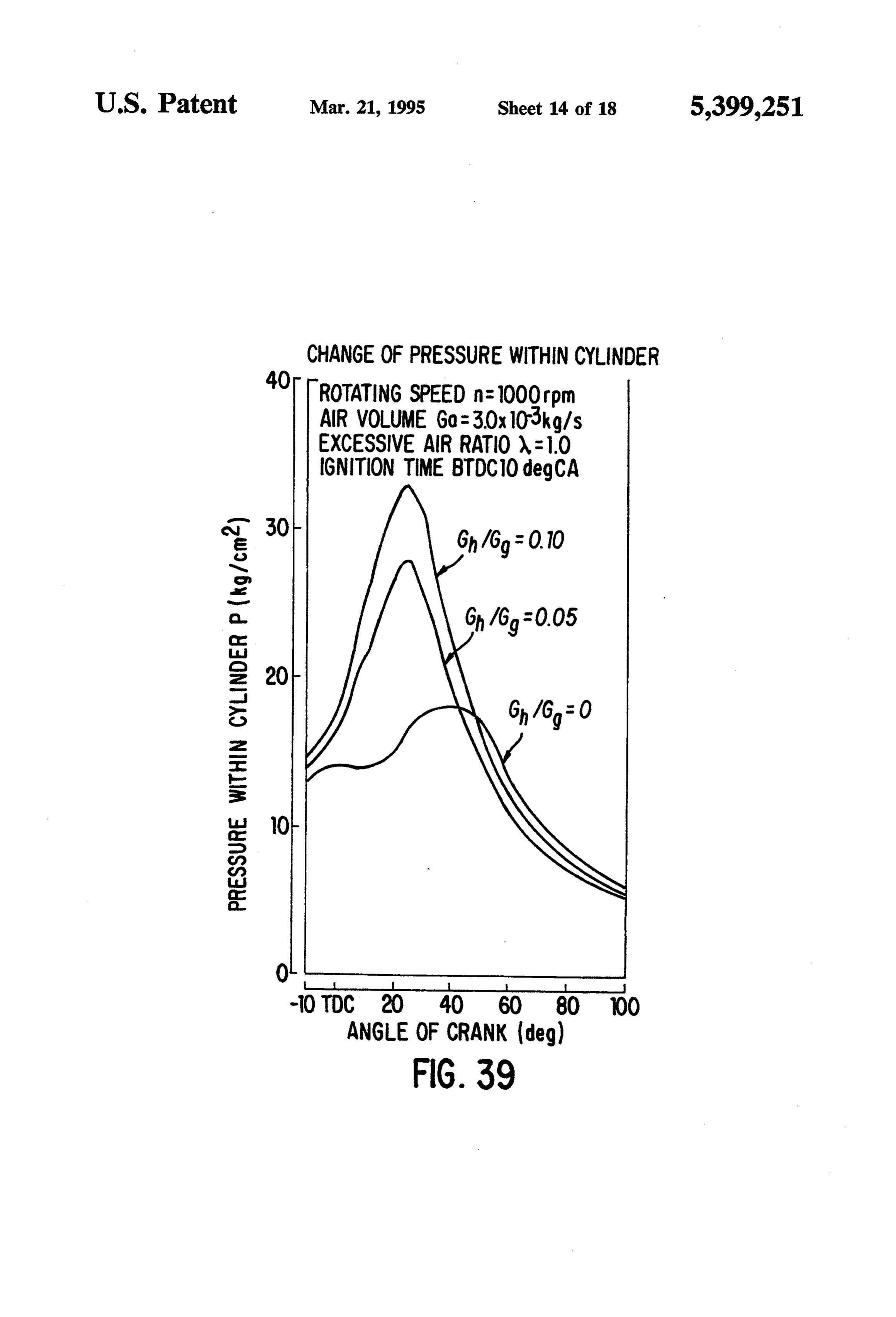
hydrogen. The absolute value of CO exhaust rate is 5 FIG. 39 is a manometric diagram showing the devel small. opment of pressure within the cylinder when changing Conventional hydrogen mixing methods cannot keep the value of Gh/Gg while keeping the air excessive the HC density at a low level when using a thinner ratio A and the ignition time constant. It is seen from mixed gas as shown by FIG. 35, unless a substantially FIG. 39 that, when increasing the ratio of flowing vol large volume of hydrogen is mixed. Therefore, conven 10 ume of hydrogen and gasoline (Gh/Gg), the time from tional hydrogen mixing methods cannot control the HC ignition until reaching maximum pressure becomes density to be low, whereas the method of the invention short and the maximum pressure increases. On this oc has the effect of keeping HC at its lowest level in any casion, as seen clearly in FIG. 3, a change in supplied case, since it automatically adjusts the volume of hydro calories Q/Q is approximately 1.02 even at gen according to the curve shown in FIG. 35. 15 Gh/Gg=0.1, and it is considered that its effect hardly FIG. 37 shows an example of measurement of the CO appears. Consequently, the difference by adding hydro density within the exhaust, and it indicates the effect of gen as shown at FIG. 39 means mainly an increase in the invention wherein in case of thin mixed gas having combustion speed.
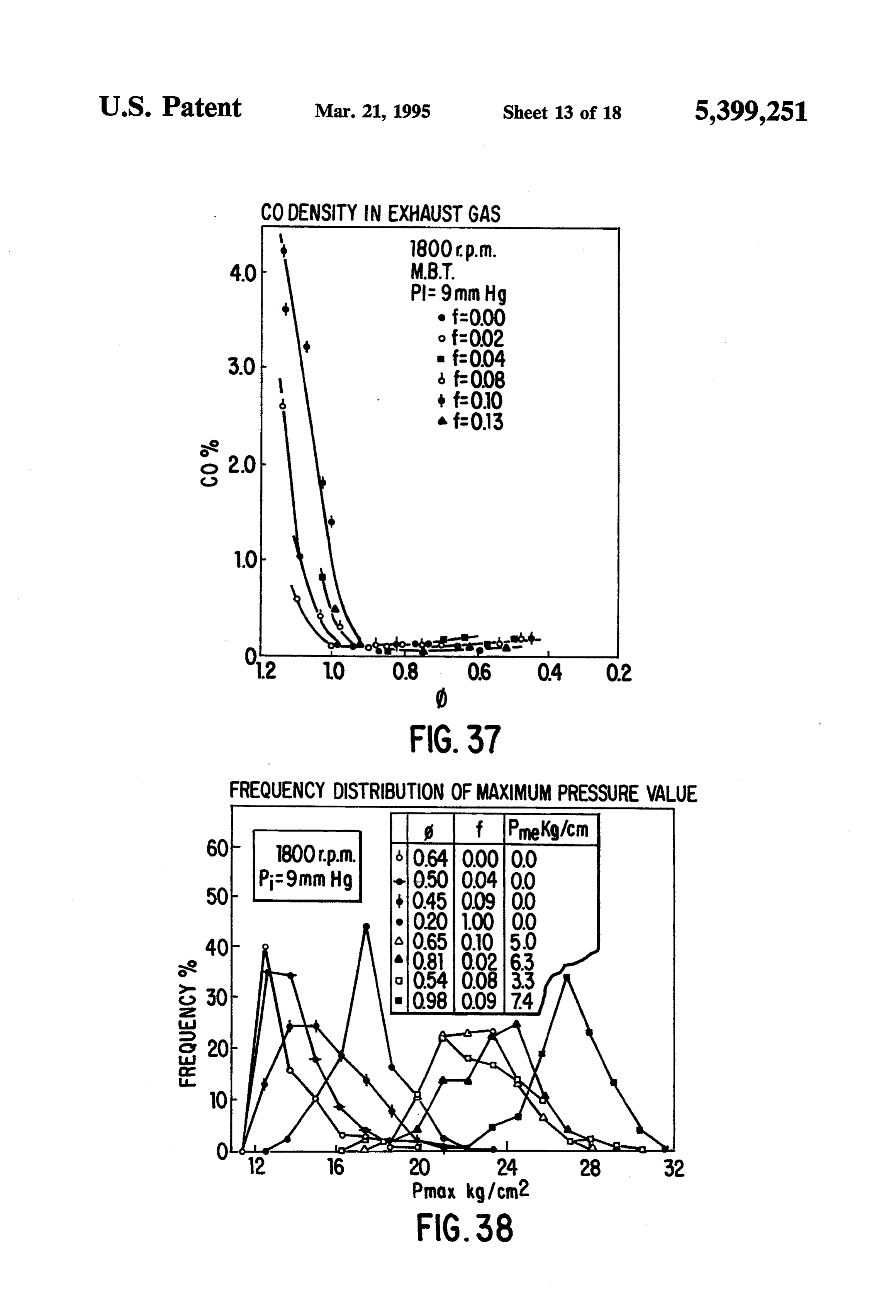
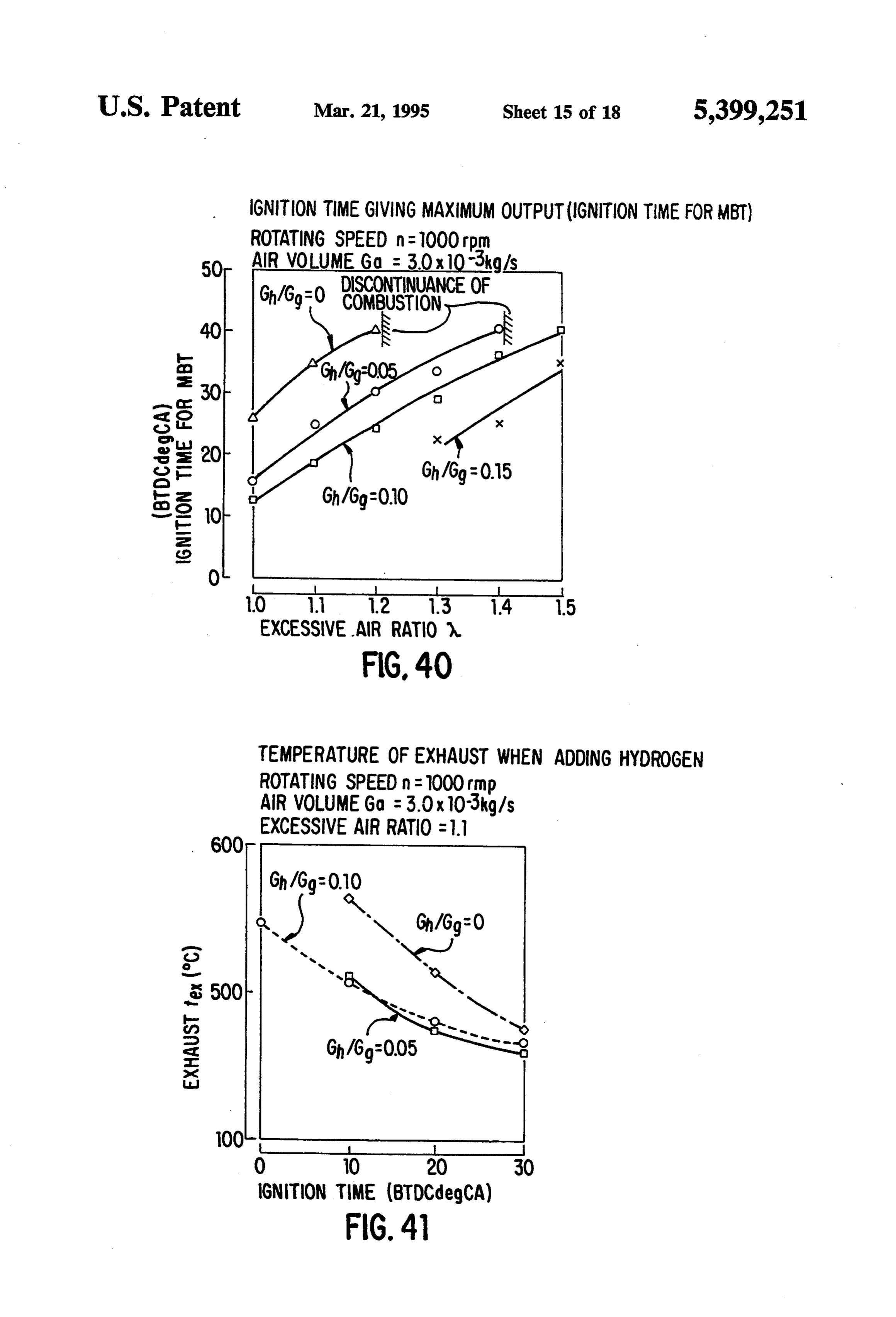
equivalent ratio d of less than 0.9, the CO density low 20 FIG. 40 shows the relationship between the excessive ers upon mixing hydrogen according to the invention. air ratio and Gh/Gg. with ignition time for MBT, and it As the mixed gas becomes thinner, it is usual for the is apparent from FIG. 39 that if Gh/Gig is increased at cycle change to increase by discontinued combustion or the same value of excessive air ratio, the ignition time drop of the combustion speed, but safe driving with thin for MBT is delayed (approaching TDC). This fact mixed gas can be obtained by mixing hydrogen accord agrees with the result of the manometric diagram (FIG. ing to the invention, and the change in the cycle de 25 39) that it is conserved for combustion speed to in Cs2SS crease, when increasing added volume of hydrogen. In FIG. 38 shows the distribution of the frequency of addition, the expansion of discontinued combustion maximum pressure wherein the range of fluctuation is limit 6 based on adding hydrogen is clear from this large when using only gasoline having equivalent ratio 30 figure.
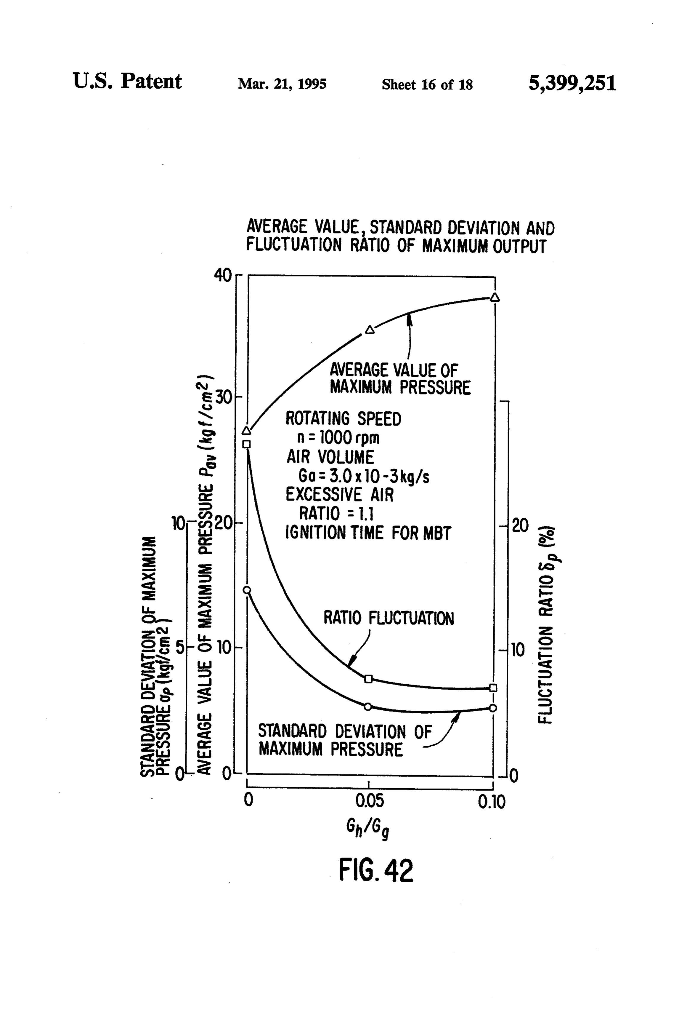
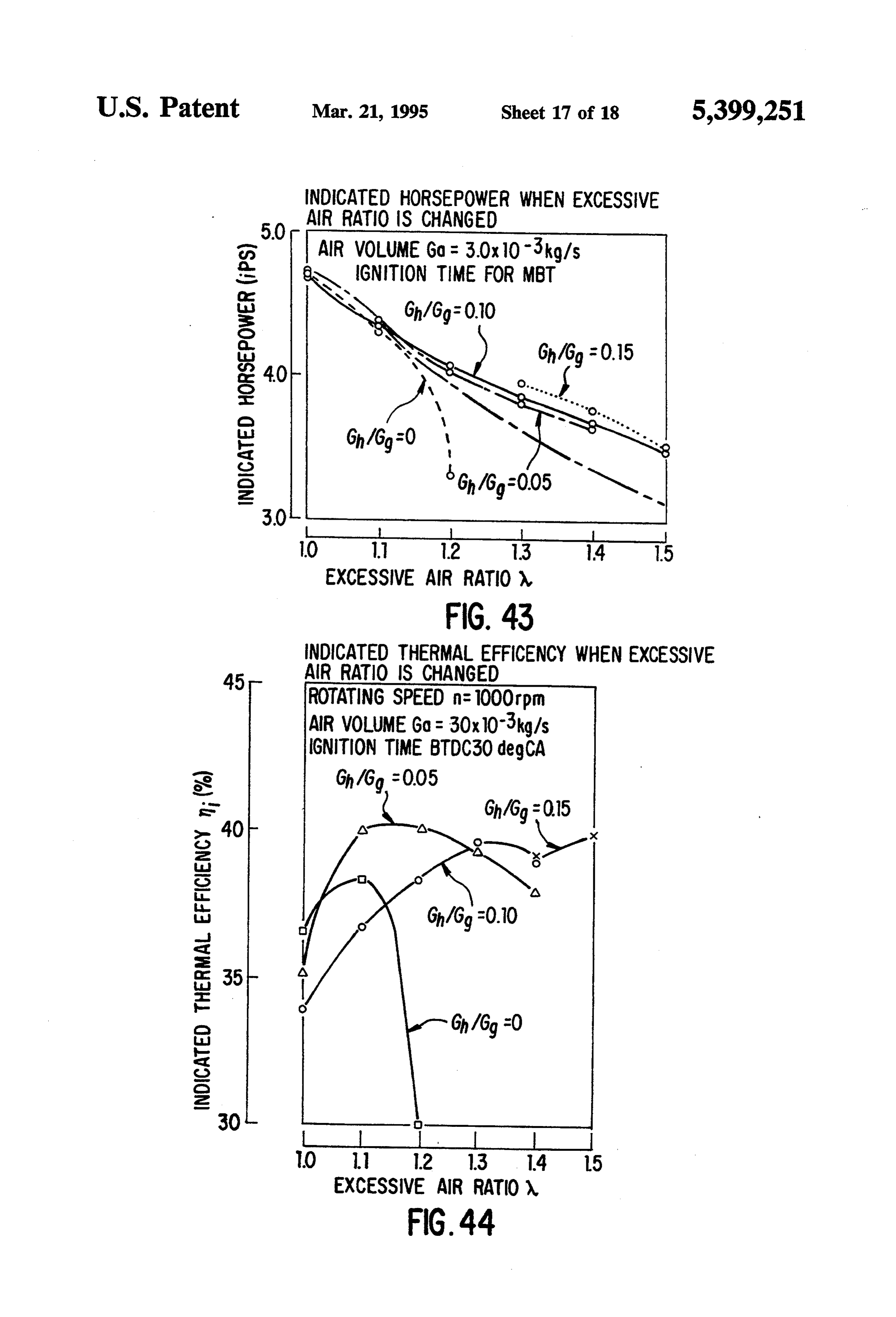
db close to 1, but it indicates the effect that mixing hy FIG. 41 shows the temperature of the exhaust mea drogen in accordance with the invention makes the sured approximately 150 mm below the exhaust valve range of fluctuation small. When using only hydrogen using a thermoelectric couple. Since the exhaust valve in accordance with the system of the invention, safe is not kept perfectly warm, the absolute value is mean driving with regular dispersion can be obtained even 35 ingless, but when compared relatively, a decrease of with mixed gas close to driving limit of thin gas. temperature is seen when adding hydrogen and corre Decreasing the ratio of maximum pressure fluctua sponds to the tendency shown by FIG. 39. The standard tion by mixing hydrogen does not change as much by deviation of and 8 of maximum pressure within the equivalent ratio, and the invention has the large effect cylinder when adding hydrogen is shown in FIG. 42. that fluctuation decreases to almost half at 10% mixing. 40 When the value of Gh/Gg is increased, both o and 8 The lower the gas suction pressure is, the bigger fluctu decrease, which means that the combustion within the ation ratio is, but the effect of mixing hydrogen in ac cylinder has been stabilized. This phenomena is consid cordance with the invention is also large. When using ered to be due to the large dispersion coefficient of gasoline only, the fluctuation ratio does not change as hydrogen and to combustion characteristics as set forth much with rotation speed. At a high speed with thin gas 45 previously. The indicated horse power at ignition time the invention has the effect that the fluctuation ratio is for MBT is shown in FIG. 43. When Gh/Gg=0, which greatly reduced by mixing hydrogen therein in accor means using gasoline only, combustion discontinuance dance with the invention. occurs at an excessive air ratio of 1.2, and the indicated As a measure to stabilize driving with thin mixed gas, horsepower sharply f11s. When Gh/Gg=0.05, it was there is a method using simultaneous ignition at two 50 possible to drive until an excessive air ratio A of 1.4, but places. The method of the invention has the same effect discontinuance of combustion occurred at an excessive when using two plugs as when using a single ignition air ratio of 1.5. When Gh/Gg=0.15, it was impossible plug. to keep Ga=3.0x10⁻³ kg/s due to the increase in the The excessive air ratio (N) when adding hydrogen to flowing volume of hydrogen. In FIG. 43, the indicated gasoline by the invention is: 55 horsepower generally decreases with increase in the value of excessive air ratio, but if the supplied calories
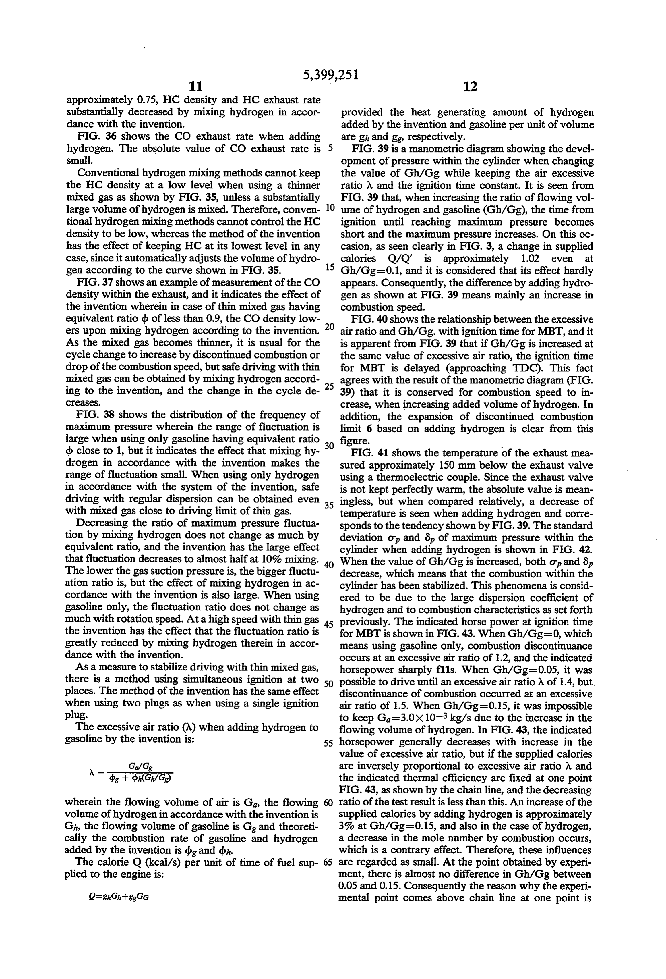
Ga/Gig are inversely proportional to excessive air ratio A and ^- (6/G) the indicated thermal efficiency are fixed at one point FIG. 43, as shown by the chain line, and the decreasing wherein the flowing volume of air is Ga, the flowing 60 ratio of the test result is less than this. An increase of the volume of hydrogen in accordance with the invention is supplied calories by adding hydrogen is approximately Gh, the flowing volume of gasoline is Gig and theoreti 3% at Gh/Gg=0.15, and also in the case of hydrogen, cally the combustion rate of gasoline and hydrogen a decrease in the mole number by combustion occurs, added by the invention is dig and dbh. which is a contrary effect. Therefore, these influences The calorie Q (kcal/s) per unit of time of fuel sup 65 are regarded as small. At the point obtained by experi plied to the engine is: ment, there is almost no difference in Gh/Gg between 0.05 and 0.15. Consequently the reason why the experi 2=ghCh-ggGG mental point comes above chain line at one point is
Page 26
considered to be an enhancement of the indicated heat condition that the mixed gas is thin and mixing rate efficiency. is small.
FIG. 44 shows the change in indicated heat efficiency 1-(3) In accordance with the invention, the maximum mi when changing Gh/Gg and the excessive air ratio. It pressure within the cylinder rises, the ignition time is impossible to compare this directly with the condi 5 for MBT is delayed, the exhaust temperature falls, tions of FIG. 43 because of the different adding time, the drop of indicated horsepower is less when in but the enhancement of indicated heat efficiency with creasing the air excessive ratio, and the indicated increases in excessive air ratio is definite, except for the heat efficiency is enhanced. range of decrease in indicated heat efficiency by imper 1-(4) The invention has the effect that, when less than fect combustion at the time when the combustion is 10 an equivalent rate of 1, the NO exhaust ratio at the about to discontinue. This is why it is considered that lag angle of ignition decreases in comparison with when approaching air cycle cyan increase in excessive the case when using gasoline only, even at same air ratio, thermal loss decreases upon a fall of the com equivalent rate. The NO exhaust decreases at an bustion temperature. Moreover, the theoretical thermal 15 ignition time for MBT of 1.0 to 1.1. efficiency mth of the auto-cycle of air only under the 1-(5) The invention has the effect that it is possible to conditions of this experiment is approximately 47%. lower the HC exhaust ratio at a rarefied area. Be FIG. 45 illustrates an example of applying the system cause of its expanded limit in discontinuance of of the invention to an electric automobile. combustion, the HC exhaust can control a sharp Film 50 has holes and is sandwiched between two increase on the rarefied side of fuel. The C0 exhaust plastic film plates 51, and film 50 is fixed in box. 49. The 20 is the same as the HC exhaust. As a result of driving platinum plates serve as electrodes, and the air at room at an air excessive ratio equal to or exceeding 1.0, temperature freely enters through the hole 52. When the absolute value becomes low. The HC exhaust hydrogen from the hydrogen generating apparatus 39 is can prevent sharp increases of HC exhaust around supplied from hole 53 and exposed to gas mixed with 25 the discontinuance of combustion with the value of oxygen within the air, one electrode produced a voltage excessive air ratio.
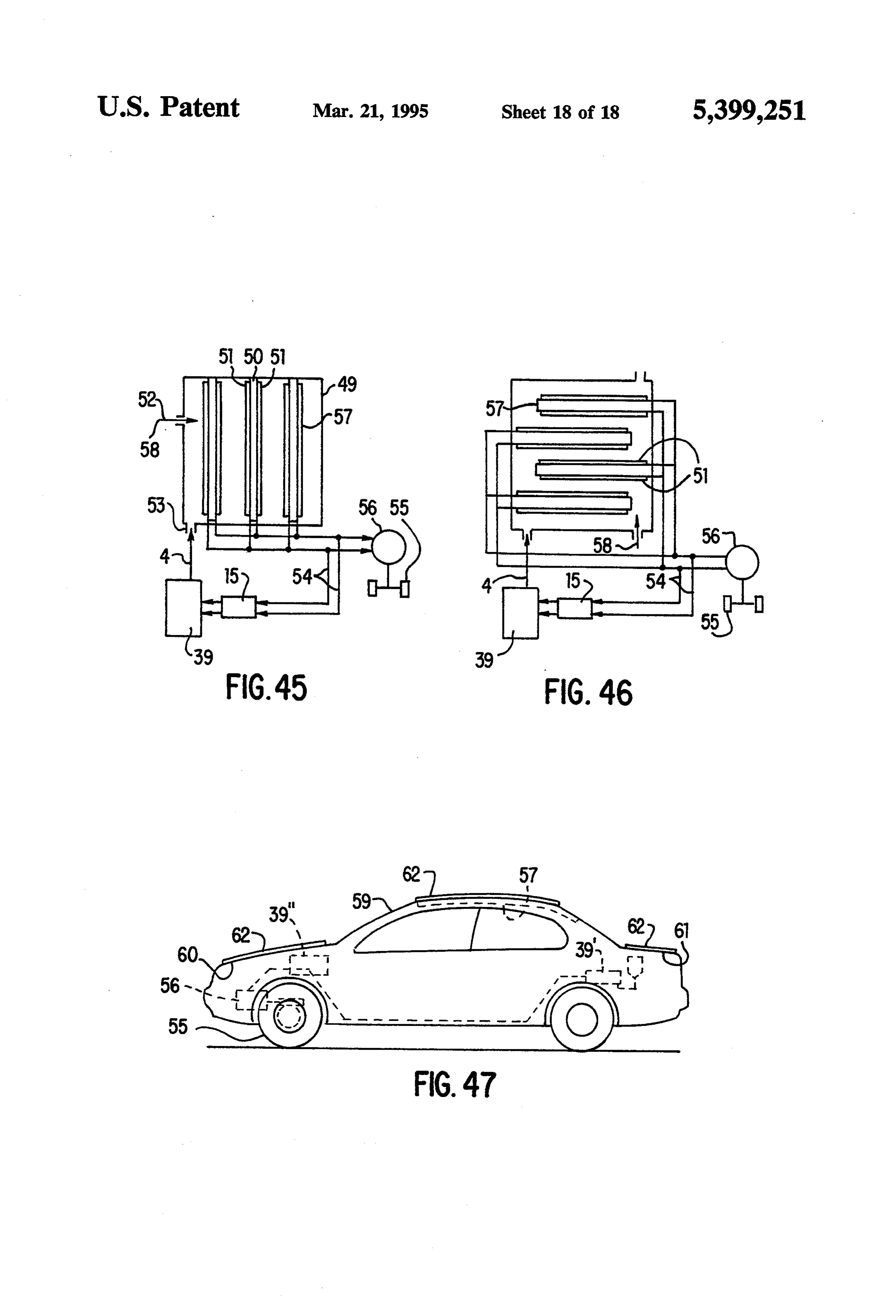
of 1 V. If N volts are required, N electrodes are 1-(6) CO exhaust does not increase sharply around the same discontinuance of combustion as the HC mounted in the box. Since a thin electrode, like a micro exhaust. As a result of driving at an excessive air chip, has high energy efficiency, it is possible for an ratio equal to or exceeding 1.0, the absolute value electrode weighing 1 kg. to produce electric power of 1 30 of the CO exhaust ratio is extremely low. kw. Part of the electric power serves as a supply source 1-(7) There is the effect that the cycle fluctuation of power supply circuit 15 for the energy system of the ratio decreases in accordance with the invention invention via 54, and most of the electric power is sup and it decreases to approximately half at a 10% plied to the motor 56 for driving the wheels 55 of auto mixing ratio, resulting in an increase of the maxi mobile. An apparatus incorporating this film fuel bat 35 mum pressure and a delay of MBT ignition time. tery and hydrogen generating apparatus into one unit is 1-(8) The rising ratio of pressure within the cylinder also contemplated by the invention. increases by adding hydrogen and the maximum FIG. 45 shows an example of the invention wherein pressure increases. In addition, the MBT ignition fuel batteries are placed sideways (horizontally). FIG. time is delayed.
46 shows an example of the invention wherein fuel 1-(9) The exhaust temperature decreases when hy batteries 57 are placed longitudinally and hydrogen 4 drogen is added.
and air 58 are fully used when rising to contact the 1-(10) It is possible to expand the limitation in discon electrodes 51. tinuance of combustion in a large range of exces FIG. 47 shows an example of the invention compris sive air ratios by adding hydrogen. If the excessive ing an electric automobile wherein solar batteries are 45 air ratio is increased, the indicated heat efficiency is attached to the outside of the roof 59 and the upper side enhanced.
of hood 60 and trunk lid 61. The hydrogen generating 1-(11). In order to decrease composition of air pollu apparatus 39 is fixed at the rear portion 39' or front tion exhausted from an automobile engine, a rar portion 39" within the car, and the film batteries 57 are efied combustion method has been tried, but an attached to the inside of roof 59. Electric power is ob 50 engine for using this method is complicated in con tained by supplying to the film fuel battery 57 hydrogen parison with a conventional engine. The invention produced by the hydrogen apparatus 39 and by electric is an epoch making one which can realize low power generated from the solar batteries operating by environmental pollution without changing the con sunlight, together with air. The electric power together struction of conventional automobiles and engines. with part of electric power from solar battery 62 is 55 1-(12) Hydrogen has a wide combustion range, high supplied to the motor 56 driving the wheels 55. combustible speed, lower ignition energy and is The outlet pipe 20 of the system is fixed within the adaptable to more easily making uniform mixed suction pipe of a ready-made gasoline engine to cause gas, as compared with gasoline. Therefore, the the following effects: invention is an epoch making one which can realize 1-(1) The limit of discontinuance of combustion, with the combustion of thin mixed gas and decreases in thin fuel density is increased. The invention has the exhausting nitric oxide by making use of these effect that the equivalent ratio of the limit in driv properties.
ing with thin fuel can more effectively be reduced 1-(13) Since the system of the invention adequately as the load decreases. controls the volume of hydrogen according to the 1-(2) The invention has the noticeable effect that it is 65 size of load, thinness of mixed gas, size of mixing possible to adequately increase combustion speed ratio and ignition time for MBT, it has the maxi of the engine and accelerate the speed of combus mum effect on non environmental pollution and tion of thin mixed gas on turbulent flow under the fuel saving.
Page 27
1-(14) The system of the invention, when assembling 10. Since the invention can heat water with the semi a controller, hydrogen generating apparatus and conductors used for the power source and at the hydrogen tank, can make a hydrogen generating same time cool semi-conductors, it is superior in apparatus that is smaller and lighter than usual. efficiency and reduces the size of the apparatus. 1-(15) Even when using mixed gas close to limit of 5 11. A rise in water temperature does not flow back driving with thinned gas, safe driving similar to ward to the side of water tank but is concentrated those when using normal distributed gas, can be on the side of electrolytic film only. Consequently, obtained with the invention. the water temperature can rise effectively with less 1-(16) In addition to the effects when applying the energy.
invention to conventional gasoline engine as set 10 12. It is possible for the operating voltage to be con forth above, the invention can eliminate air pollu trolled to be 10% lower by increasing the water tion, especially in the use of current diesel engine temperature.
trucks, particularly with respect to exhaust gas 13. Electric cars, etc. superior in efficiency can be discharged when driving at low speeds within a 15 made by the system of the invention, in combina city, without changing the construction of the die tion with the film battery set forth above. sel engine truck. The invention has an ideal effect as a new energy In addition to the advantages of the invention set source and is a revolutionary one, providing the same forth above, the effect of the invention is: influence as the industrial revolution caused by James 1. It is possible to make an automobile driven by Watt's steam locomotive.
hydrogen only, instead of mixing the hydrogen In addition to the above, the invention may be em with gasoline, i.e. an automobile driven by water. ployed with a methanol car, a solar cell car, and electric 2. In accordance with the invention it is possible to car, a CNG car, a hydrogen car, a gas turbine car, a Sterling cycle engine, a hydro car (electric-diesel), drive a motor bicycle, vessel, jet airplane, rocket and a carjointly using LPG, etc. Variations other than (solar battery is used for power source and water is mentioned above are contemplated and considered to obtainable from space) and also to an operate elec 25 be within the scope of the invention. tric power generator, aluminum refinement, fur While the invention has been disclosed and described nace, iron manufacture, burner, etc. by using wa with reference to a single embodiment, it will be appar ter.
ent that variations and modification may be made 4. Since energy that has a clean exhaust can be ob 30 therein, tained, such problems as the exhaust gas of automo claims toand it is therefore intended in the following cover each such variation and modification as bile and exhaust materials from atomic power gen falls within the true spirit and scope of the invention. eration do not occur. What is claimed is:
5. A particular liquid such as an electrolytic liquid is 1. A system for generating hydrogen and oxygen not required and regular water is usable. There 35 comprising a tank having a bottom portion, a solid poly fore, water is obtainable from water taps and there electrolyte film in said tank separating said tank into is no need of going to a gas station. first and second portions with opposed first and second 6. The energy converting ratio is as high as 95% sides facing said first and second portions, respectively, 7. Since the system is small and light and it is also electrodes on said first and second opposite sides of said operated by battery and portable, it can be placed film, a power supply means connecting said power in small space such as under the hood of an auto supply to said electrodes, means for introducing water mobile, and is usable for conveyances such as auto into said bottom portion of said first portion of said mobiles. tank, wherein said tank does not have an electrolytic 8. Oxygen obtained together with the hydrogen can liquid therein and said water is separated into hydrogen not only improve the cabin environment of auto 45 and oxygen by polyelectrolyte water electrolysis, vi mobile, etc. but can also prevent traffic accident by brating means to vibrate said polyelectrolyte film, elec preventing the sleeping of the driver and by im trodes, and water in said tank, a power regulator for proving the driver's attentiveness. regulating power from said power supply, said power 9. The invention quickly takes away produced foam regulator including an electronic element that generates of hydrogen from film 8 when driving the car or 50 heat, and means for mounting said electronic element in engine, and also by placing the water tank 6 at a said bottom portion of said tank for heating said water high position, and the method of connecting pipe 9 by heat generated thereby.
so that pressure of water on electrolytic film is 2. The energy system of claim 1 wherein said power increased. Therefore, permeation of water 1 into regulator comprises means for supplying a constant electrolytic film 11 is accelerated and the electro- 55 current to said polyelectrolyte electrolytic film. lytic effect is larger than publicly known. sk k
Provenance
- Collection
- Cited prior art
- Original PDF
- patentimages.storage.googleapis.com →
- Filed
- 1993-11-10
- Pages
- 27
- Method
- pdftotext (the PDF's own text layer) + pdftoppm 300dpi page scans
- Source
- Google Patents bibliographic record
- Granted
- 1995-03-21
- Inventors
- Yoshiro Nakamats
- Transcribed from
- patentimages.storage.googleapis.com →