patent · US5196104
Oxygen and hydrogen gas driven turbine
23 March 1993
Page 1 — bibliographic record
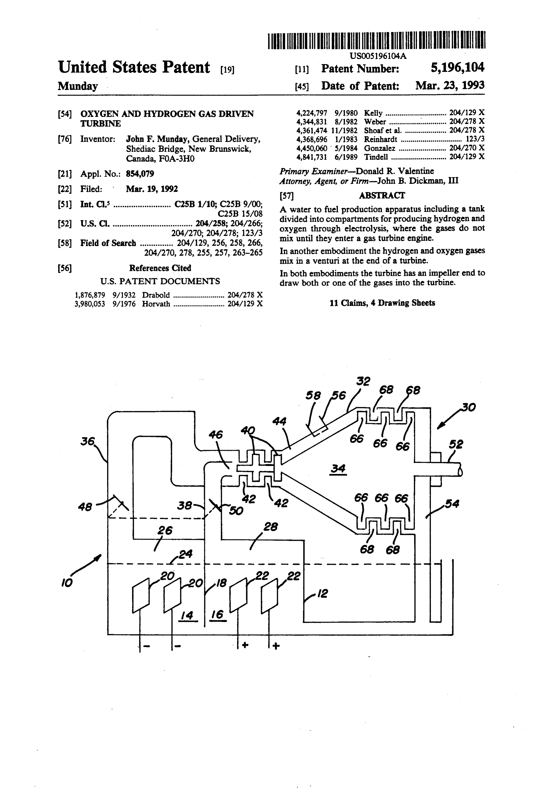
United States Patent (19) 11 Patent Number: 5,196,104 Munday 45) Date of Patent: Mar. 23, 1993 (54) OXYGEN AND HYDROGEN GAS DRIVEN 4,224,797 9/1980 Kelly ............................... 204/129 X TURBINE 4,344,831 8/1982 Weber ....... ... 204/278 X 4,361,474 11/1982 Shoaf et al...................... 204/278 X (76) Inventor: John F. Munday, General Delivery, 4,368,696 l/1983 Reinhardt ............................... 123/3 Shediac Bridge, New Brunswick, 4,450,060 5/1984 Gonzalez ........................ 204/270 X Canada, FOA-3HO 4,84,731 6/1989 Tindell ............................ 204/129 X 21 Appl. No.: 854,079 Primary Examiner-Donald R. Valentine Attorney, Agent, or Firm-John B. Dickman, III (22 Filed: Mar. 19, 1992 57 ABSTRACT 51) Int. C. .......................... C25B 1/10; C25B 9/00; A water to fuel production apparatus including a tank
52 U.S. C. .................................... 204/258; 204/266; divided into compartments for producing hydrogen and 204/270; 204/278; 123/3 oxygen through electrolysis, where the gases do not 58) Field of Search ............... 204/129, 256, 258, 266, mix until they enter a gas turbine engine. 204/270,278, 255, 257, 263-265 In another embodiment the hydrogen and oxygen gases 56) References Cited mix in a venturi at the end of a turbine. In both embodiments the turbine has an impeller end to
1,876,879 9/1932 Draboid .......................... 204/278 X 3,980,053 9/1976 Horvath .......................... 204/129 X 11 Claims, 4 Drawing Sheets
Page 2
Drawing sheet — no readable text.
Page 3
Drawing sheet — no readable text.
Page 4
Drawing sheet — no readable text.
Page 5
Drawing sheet — no readable text.
Page 6
A small amount of sulphuric acid is added to assist the
OXYGEN AND HYDROGEN GAS DRIVEN electrolysis process. Provided the water is not drained TURBNE or leaks out of the water fuel tank no additional acid will be added to the water.
BACKGROUND OF THE INVENTION 5 The hydrogen gas is separated from the oxygen gas The present invention relates to a gas driven turbine, by the partition dividing the tank into two compart and in particular an oxygen and hydrogen gas driven meet isand ments the water level. The only place the two gases where turbine driven impellers commingle the turbine.
Heretofore there have been attempts to develop a fuel gases toprior to entering a gas turbine, or at a venturi for internal combustion engines to replace petroleum 10 prior net.
entering a gas turbine as in another embodi fuels. The concerns for burning petroleum fuels are well documented. Petroleum fuels are being used up and The turbine has a plurality of vanes which rotate a since there is a limited supply it is obvious that alterna rotor connected to output shafts. One of the shafts con nects to impellers for commingling the gases and pump tive sources of fuel must be developed. In addition, 15 ing them to the turbine chamber. The other of the out there are environmental reasons for a new fuel that does not pollute the atmosphere with carbon, nitrogen or put shafts connects to the input shaft of a vehicle. A sulfur based gases. The effects of atmospheric pollution continuous spark is produced in the turbine chamber. from fossil fuels are a world wide concern. Animal and There are manifolds connecting the hydrogen and oxy plant life are being destroyed by the effects of pollution. 20 gen gas chambers to the turbine assembly. Butterfly These effects range from respiratory problems in hu valves act as throttle valves, opening and closing the mans to the destruction of forest. manifolds to control the flow of the gases. Water vapor Prior art U.S. Patents show the electrolysis produc and steam produced during the ignition and subsequent tion of hydrogen and oxygen gases from the disassocia conversion of hydrogen and oxygen gases are returned tion of water. The hydrogen and oxygen gases pro 25 to the water tank.
duced are intended to be used as fuel for internal com In another embodiment only the hydrogen gas is bustion engines. pumped to the turbine by the impellers. There is a ven There is a flashback eliminator present in the present turi through which the hydrogen gas passes. The oxy application. The following is a list of U.S. Patents of gen gas is drawn through the center of the impeller interest to the present invention: 30 housing by the venturi effect to mix with the hydrogen U.S. Pat. No. 2,365,330, issued to Carmichael. gas and passed on to a combustion chamber of the tur U.S. Pat. No. 2,496,623, issued to Fragale. bine.
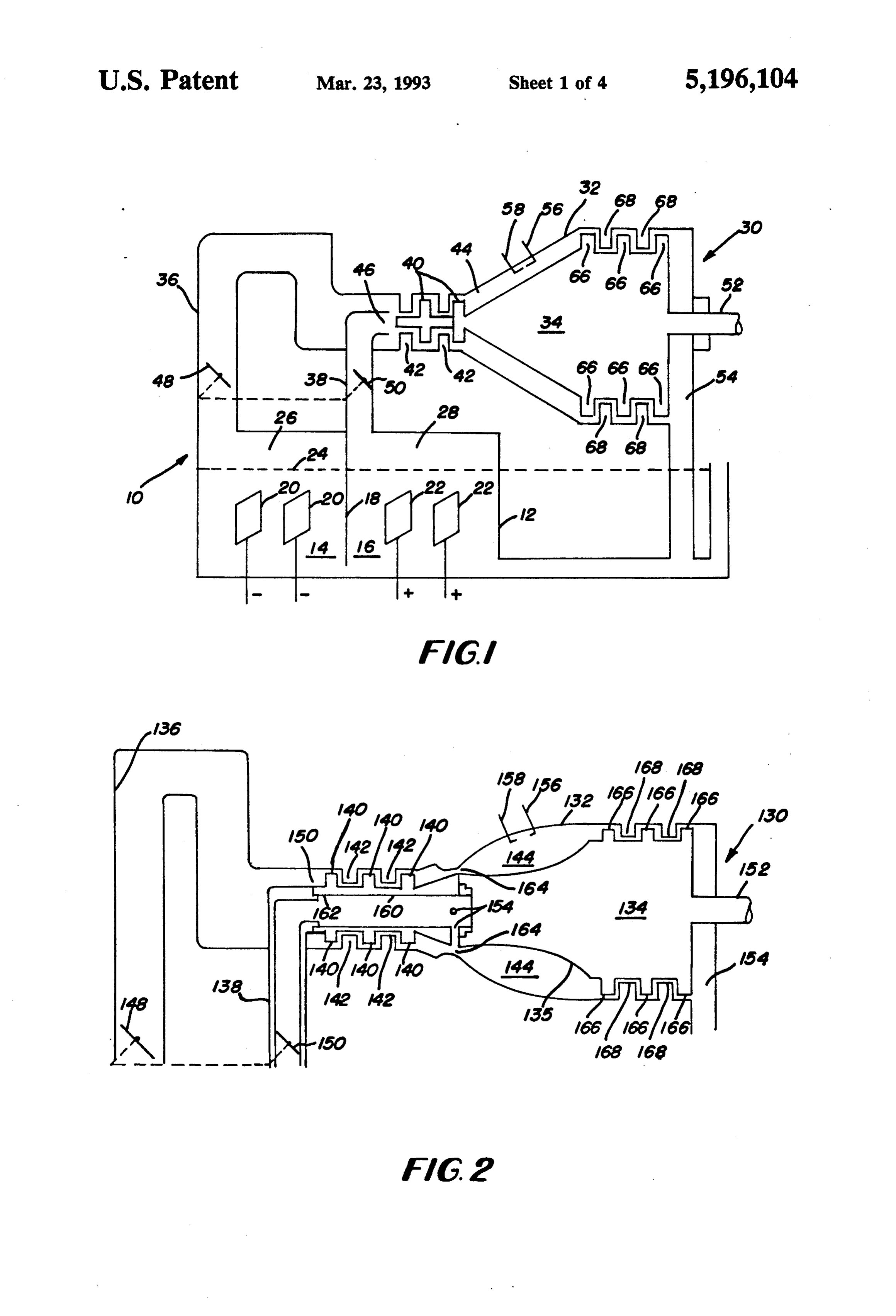
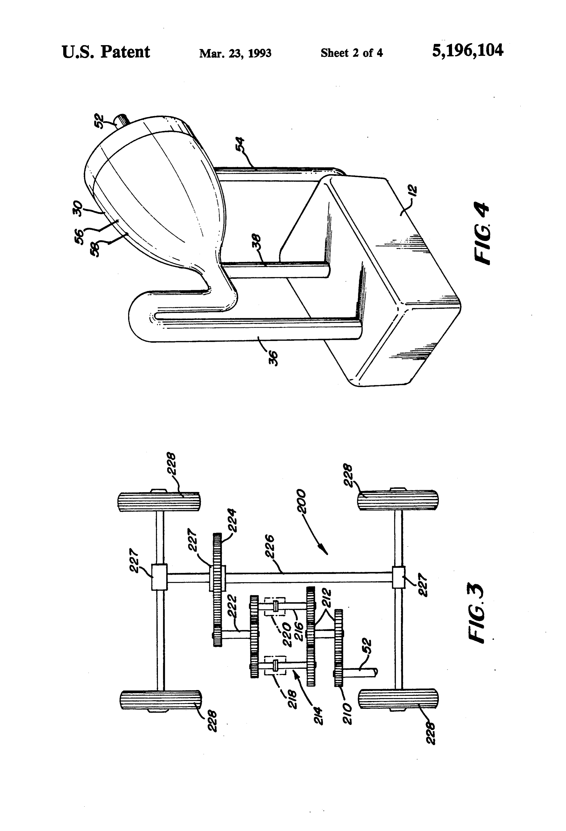
U.S. Pat. No. 4,023,545, issued to Mosher et al. There are flashback eliminators present in the differ U.S. Pat. No. 4,344,831, issued to Weber. ent embodiments of the invention. The patent issued to Carmichael is the oldest known 35 DESCRIPTION OF THE DRAWINGS reference to the inventor that is directed to the use of hydrogen and oxygen gases as a source of fuel for auto FIG. 1 is a schematic of the hydrogen and oxygen mobiles. The gases commingle just prior to entering the gases production apparatus and a gas turbine of the automobile engine, which is a reciprocating internal present invention;
combustion engine. Note, also the Fragale patent which 40 FIG. 2 is a schematic of another embodiment of the shows a reciprocating engine and the production of invention;
hydrogen and oxygen gases as fuels. FIG. 3 is a plan view of a drive train of the present The Mosher et al and the Weber patents are directed invention;
to the production of hydrogen and oxygen gases as FIG. 4 is a perspective of a water tank and turbine of fuels. 45 the present invention.
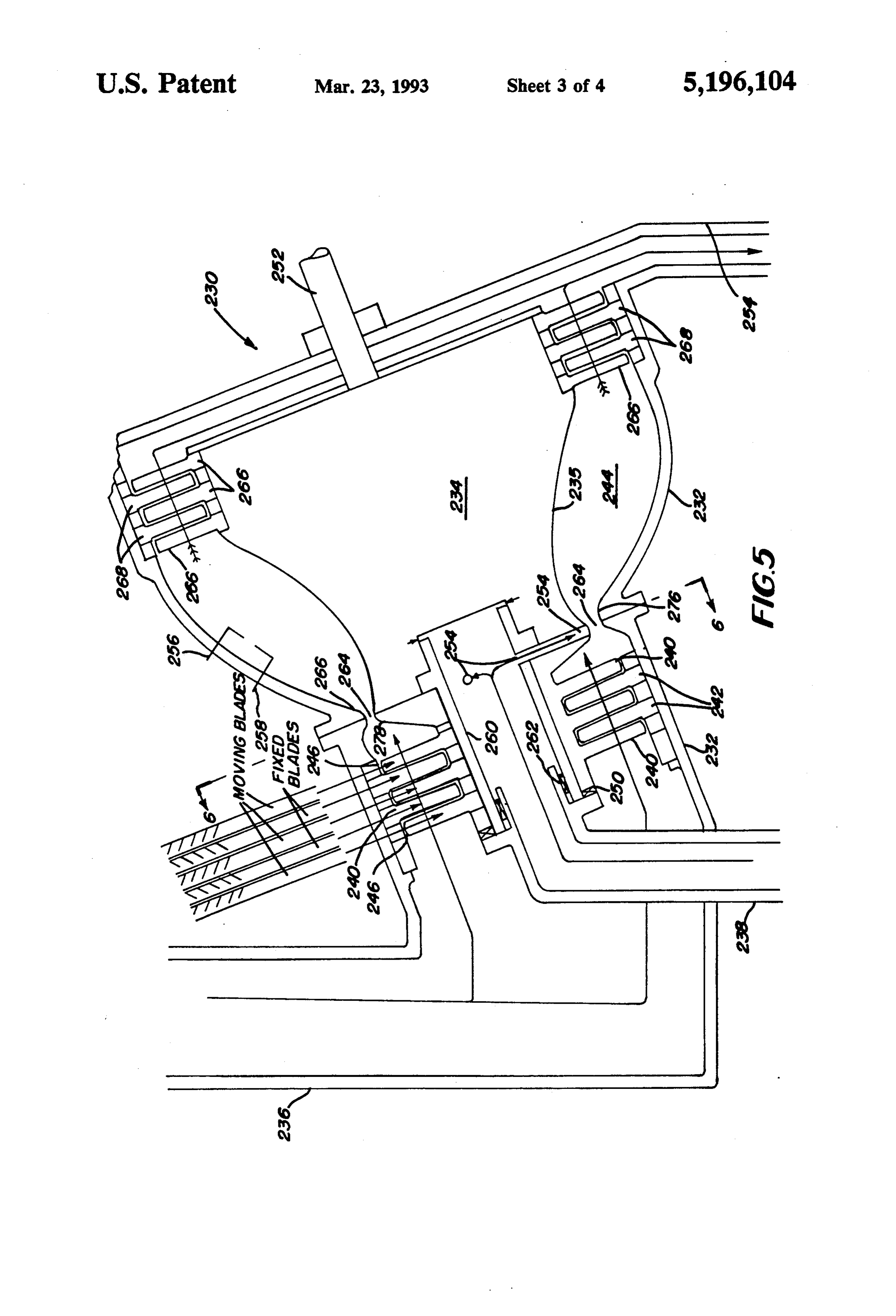
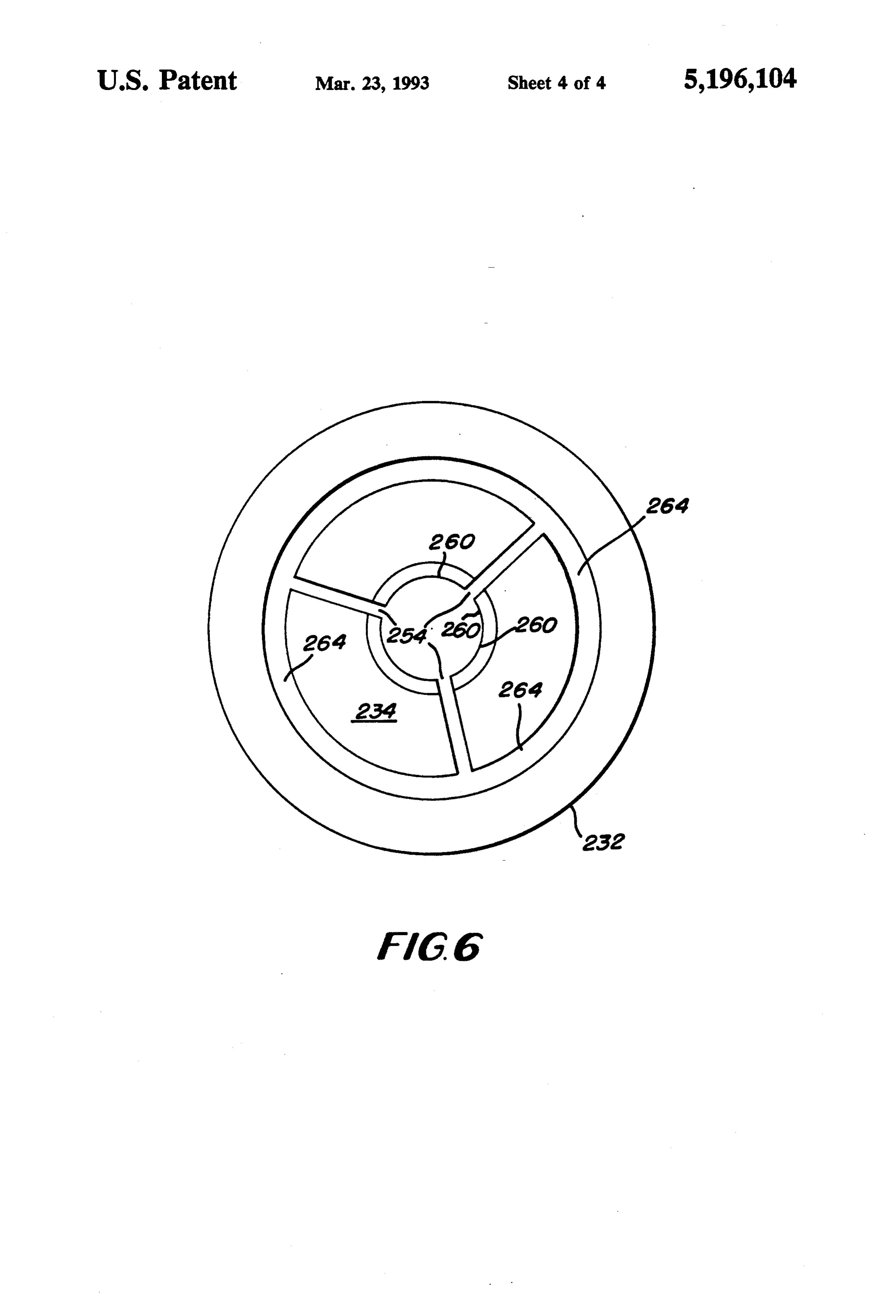
The cited references do not suggest the production FIG. 5 is a sectional view of another embodiment. and use of hydrogen and oxygen gases as fuels for tur FIG. 6 is a sectional view on line 6-6 of FIG. 5. bine engines. The present invention is directed to a DESCRIPTION OF THE INVENTION turbine engine that runs on hydrogen and oxygen gases.
50 Referring to the drawings FIGS. 1 to 6 there is
SUMMARY OF THE INVENTION shown an electrolysis apparatus and turbine combina The present invention provides an electrolysis appa tion 10. There is a water tank 12 divided into a pair of ratus for converting water to hydrogen and oxygen compartments 14 and 16 with a divider 18 separating gases and using the gases to power a turbine. the compartments. Each compartment has an equal A water fuel tank consists of two compartments, 55 number of electrodes. One set of electrodes are con separated by a partition. The partition does not extend nected to a negative direct current source to become to the bottom of the tank, thus allowing the water to cathodes 20 for attracting hydrogen gas, and the other flow freely between the compartments. The areas above set of electrodes are connected to a positive direct cur the water in each compartment form a gas collection rent source to become anodes 22 for attracting oxygen chamber for either hydrogen or oxygen. There are 60 gases. The tank 12 is filled with water to a level 24. electrodes extending into each compartment, sub Above the water level 24 is formed a pair of chambers merged in the water. The electrodes that connect to a 26 and 28 for holding hydrogen gas and oxygen gas, negative direct current source are cathodes for separat respectively.
ing hydrogen from water. Electrodes connected to a A turbine 30 having a stationary combustion chamber positive direct current source are anodes for separating 65 housing 32 and a rotor 34 is connected to chambers 26 oxygen from water. Since hydrogen and oxygen gases and 28 via manifolds 36 and 38, respectively. Integrally are lighter that water they collect in their appropriate connected to the turbine 30 is an impeller 40 and an chamber above the water level. impeller housing and stationary blades 42.
Page 7
Impeller 40 is connected to the tapered end of rotor prevent flash back of hydrogen gases in case of explo 34 so that as the rotor turns the impeller also turns, SO drawing gases into a combustion chamber 44 defined by FIG. 5 is the same drawing as FIG. 2 with the excep housing 32 and rotor 34. Oxygen manifold 38 has a tion that FIG. 5 shows greater detail.
diameter that is less than hydrogen manifold 36, thereby The embodiment of FIG. 5 shows a turbine 230 manifold 38 is mounted with an opening 46 at the end of which connects to an electrolysis 10 by hydrogen mani impeller housing 42 and inside of manifold 36 which fold 236 and oxygen manifold 238. The hydrogen mani connects to impeller housing 42. To control the flow of . fold 236 connects to turbine housing 240 which contains gases each manifold 36 and 38 has a butterfly valve 48 stator turbine blades 242. Oxygen manifold 238 extends and 50, respectively. The butterfly valves 48 and 50 are 10 through turbine housing 232 and connects a hollow connected together to operate together. shaft 260 of a turbine rotor 234. Hollow shaft 260 sup Turbine 30 has an output shaft 52 which connects to ports rotating turbine blades 240. Between the end of a vehicle drive train. There is also an exhaust end 54 oxygen manifold 238 and the inside of hollow shaft 260 through which water vapor and steam pass returning to 15 is a bronze bearing 262 to reduce any friction of the hollow rotating shaft 260. There is also a thrust bearing water tank 12. Also there are ignition spark leads 56 and 250 58 for igniting the hydrogen and oxygen gases. between hollow shaft 260 and a flange 250 on mani In operation, water tank 12 is filled with water to fold 238. Three holes 254 (two shown) spaced 120 de level 24. Direct current is passed through cathodes 20 FIG. apart grees around the hollow shaft 244 (best shown in 6) provide passages for the oxygen gas to pass and anodes 22 separating hydrogen gases and oxygen through venturi ports 264 to commingle with the hy gases from the water by electrolysis. The separated drogen gas gases travel through their respective manifolds 36 and defined by aatlobe the throat of a venturi 264. The venturi is 276 on housing 232 and a second lobe 38 to turbine 30 where they mix. Impellers 40 pump the mixed gases into combustion chamber 44 where they 278Turbine on rotor 234.
rotor 234 has an arcuate concave cross sec are ignited. The force of combusted gases rotate rotors 25 tion area 235 to increase the volume of combustion 66, thereby rotating output shaft 52.
In FIG. 2, another embodiment of a turbine is shown. bustion chamber 244 to chamber 244, similar rotor 134 in FIG. 2. The con
Turbine 130 has a combustion chamber housing 132 and and rotor 234, which provides by is defined turbine housing 232 a rotor 134. Between the housing 132 and rotor 134 is a burning hydrogen and oxygen gases. The chamber a circular force of for the combustion chamber 144. A pair of spark electrodes 156 30 ignition of the gases create a force on turbine impellers and 158 extend into combustion chamber 144. Rotor 34 266 and 268. Impeller 266 are mounted on rotor 234, has an arcuate concave cross section area 135 to in while stationary impellers 268 are mounted on the inside crease the volumn of combustion, Connected to one end of housing 232. Exhaust gases leaving the impellers are of rotor 134 in a hollow shaft 160 which rotates on bearings attached to the oxygen manifold at 162. Sur 35 converting or have converted to steam and water vapor to return to the electrolysis apparatus 10 through ex rounding impellers 140 is an impeller housing 142 which haust manifold 254.
connects to hydrogen gas manifold 136. Oxygen gas FIG. 6 shows hollow shaft 260 and the ports 254 for manifold 130 cerries the bearing and thrust bearing for passage of oxygen gas. Ports 254 are aligned with ven the end of the hollow shaft 162 to locate and permit the turi passages 264 in rotor 234. Also shown is housing oxygen gas to pass the said hollow shaft through the 232 and venturi throat 264.
passage ways 154 out of the venturi at 164. It will, of course, be understood that various changes The end of the rotor 134 connected to the hollow may be made in the form, details, arrangement and shaft 160 rotates at 162 on oxygen housing 138 cooper proportions of the various parts without departing from ates with a venturi opening 164 and the hydrogen gas the scope of the invention.
pump through the venturi opening by impellers 140 to 45 I claim:
draw oxygen gas into the combustion chamber where it 1. A water to fuel production apparatus for providing mixes with hydrogen gas just prior to ignition. The fuel for a gas turbine engine, comprising: combusted gases rotate the rotor 134 by passing be a fuel production tank having a first compartment tween the housing 132 and rotor impellers 166. Steam and a second compartment, where a divider seals and water vapor are exhausted through exhaust opening 50 each compartment from the other at the top of the 154 to a water tank of an electrolysis system, not shown. tank, and connect said compartments along the Turning to FIG. 3, there is shown a drive train 200 of bottom of the tank;
an automobile. There is a drive shaft 52 which connects said first compartment having cathodes for the pro to output shaft 52 of turbine 30. Shaft 52 has a gear 210 duction of hydrogen, and connected to a hydrogen that drives gear system 212. A pair of magnetically 55 manifold for removing hydrogen gas from the clutched gear systems 214 and 216 are selectively en compartment;
gaged by gear system 212. Magnetic clutches 218 and said second compartment having anodes for produc 220 move the gear systems 214 or 216 into engagement. tion of oxygen, and connected to an oxygen mani An output gear system 222 will rotate clockwise or fold for removing oxygen gas from the compart counter-clockwise according to which gear system 214 ment;
or 216 is engaged. A driven gear 224 or driven shaft 226 said oxygen manifold having a diameter of a size to fit turns wheels 228. Differential gears 227 are used to give within said hydrogen manifold whereby said gases stability to the All Wheel Drive assembly. This is a will mix together where the open ends of said man typical gear system which can be used with the present ifold meet; m hydrogen gas and oxygen gas fuel operated turbine. 65 said hydrogen manifold being connected to a turbine FIG. 4 is a showing of a turbine 30 connected by having an intake end with impellers for pumping manifolds 36 and 38 to electrolysis apparatus tank 12. said mixed gases into said turbine, where they sub The hydrogen manifold 36 has an inverted U-bend to sequently ignite.
Page 8
2. A water to fuel production apparatus as in claim 1 a turbine means having a housing, a power shaft end wherein said turbine has a ststionary housing, a rotor and an intake end for receiving hydrogen and oxy provided with an output shaft and an input shaft con gen gases, and a rotor means within said housing; nected to said impellers. said rotor having a first end with a power shaft means 3. A water to fuel production apparatus as in claim 2 5 and a second end with a hollow rotary shaft; wherein said cathodes and anodes being supported in a plurality of first rotary impeller means on said hol tank having electrical leads connected to a source of d. low rotary shaft, and a plurality of first stationary c. current to produce hydrogen and oxygen by electrol impeller means on said housing, where said plural ySls. ity of first rotary impeller means alternate between 4. A water to fuel production apparatus as in claim 3 O said plurality of first stationary impeller means; wherein said hydrogen manifold has an inverted U a plurality of rotary drive impeller means on said bend to trap lighter hydrogen gases above the atmo rotor at said first end and a plurality of stationary spheric gases to safely burn any premature ignition. drive impeller means on said housing at said power 5. A water to fuel production apparatus as in claim 4 shaft end, where said plurality of rotary drive im wherein said turbine has a water vapor and steam return 15 pellers on said rotor alternate between said plural to said water tank. ity of stationary impeller means; 6. A water to fuel production apparatus for providing a combustion chamber between said rotor and said fuel for a gas turbine engine, comprising: turbine housing having ignition means connected a fuel production tank having a first compartment 20 saidto hollow said source of electricity;
rotary shaft having a plurality of bores and a second compartment, where a divider seals which connect to a plurality of venturiapertures in each compartment from the other at the top of the said rotor, and a venturi means between said rotor tank, and connect said compartments along the and said housing where said venturi apertures ex bottom of the tank;
said first compartment having cathodes for the pro 25 saidtend to said venturi means; turbine intake end being connected to said hy duction of hydrogen, and connected to a hydrogen drogen manifold, where said hydrogen gas from manifold for removing hydrogen gas from the said electrolysis apparatus is drawn into said tur compartment; bine by said rotary first impeller means and said said second compartment having anodes for produc first second impeller means; tion of oxygen, and connected to an oxygen mani 30 said turbine hollow rotary shaft being connected to fold for removing oxygen gas from the compart said oxygen manifold, where oxygen gas from said ment; electrolysis apparatus is drawn into said turbine by said oxygen manifold having a diameter of a size to fit said venturi means, and the hydrogen gases com within said hydrogen manifold whereby said gases mingle with said oxygen gases at said venturi will mix together where the open ends of said man 35 means.
ifold meet; 8. A combination water to fuel electrolysis apparatus said hydrogen manifold being connected to a turbine and gas driven turbine as in claim 7 wherein said turbine having an intake end with impellers for pumping has an exhaust manifold at said power shaft end to re said hydrogen through a venturi in said turbine, turn steam and water vapor produced by the ignition of said oxygen manifold being connected to said ven hydrogen and oxygen gases in said combustion cham turi whereby said hydrogen gas flow draws said ber.
oxygen gas into said turbine where said gases mix 9. A combination water to fuel electrolysis apparatus and are subsequently ignited. and gas driven turbine as in claim 8 wherein said com 7. A combination water to fuel electrolysis apparatus bustion chamber is positioned between said plurality of and a gas driven turbine comprising; 45 first impeller means and said plurality of drive impeller an electrolysis apparatus for converting water to means and said housing on said rotor, said rotor having hydrogen gas and oxygen gas, where said appara a concave surface to increase the volume of said com tus includes a fuel production tank having a first bustion chamber.
compartment and a second compartment separated 10. A combination water to fuel electrolysis appara by a divider which seals one compartment from the 50 tus and gas turbine as in claim 9 wherein said plurality other at the top of said tank, and where said com of bores and said plurality of venturi apertures includes partments connect along the bottom of said tank; at least three equally spaced bores in said hollow rotary said first compartment having cathodes for the pro shaft and at least three equally spaced venturiapertures duction of hydrogen, and connected to a hydrogen in said rotor where said bores and said apertures are manifold for removing hydrogen gas from said 55 aligned.
compartment; 11. A combination water to fuel electrolysis appara said second compartment having anodes for the pro tus and gas turbine as in claim 10 wherein said venturi duction of oxygen and connected to an oxygen means includes a first lobe means on the housing and a manifold for removing oxygen gas from said com second lobe means on said rotor to provide a restricted partment; venturi opening, and said venturi apertures extend to said cathodes and said anodes being connected to a said restricted venturik opening. . . . . source of electricity;
Provenance
- Collection
- Cited prior art
- Original PDF
- patentimages.storage.googleapis.com →
- Filed
- 1992-03-19
- Pages
- 8
- Method
- pdftotext (the PDF's own text layer) + pdftoppm 300dpi page scans
- Source
- Google Patents bibliographic record
- Granted
- 1993-03-23
- Inventors
- John F. Munday
- Transcribed from
- patentimages.storage.googleapis.com →