patent · US4818638
System for hydrogen thermal-electrochemical conversion
4 April 1989
Page 1 — bibliographic record
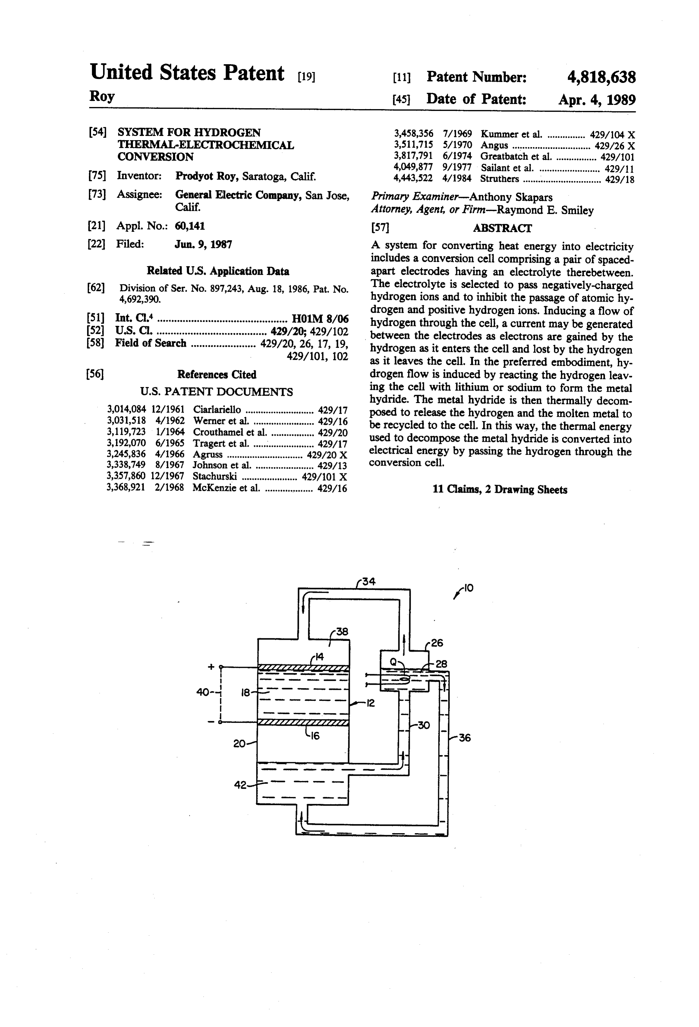
United States Patent (19) 11 Patent Number: 4,818,638 Roy 45 Date of Patent: Apr. 4, 1989 54 SYSTEM FOR HYDROGEN 3,458,356 7/1969 Kummer et al. ... ... 429/104X THERMAL-ELECTROCHEMICAL 3,511,715 5/1970 Angus ............. ... 429/26X CONVERSION 3,817,791 6/1974 Greatbatch et al. ... 429/01 4,049,877 9/1977 Sailant et al. ........................ 429/11 (75) Inventor: Prodyot Roy, Saratoga, Calif. 4,443,522 4/1984 Struthers ............................... 429/18 73) Assignee: General Electric Company, San Jose, Primary Examiner-Anthony Skapars Calif. Attorney, Agent, or Firm-Raymond E. Smiley (21) Appl. No.: 60,141 57 ABSTRACT (22 Filed: Jun. 9, 1987 A system for converting heat energy into electricity includes a conversion cell comprising a pair of spaced
Related U.S. Application Data apart electrodes having an electrolyte therebetween. 62) Division of Ser. No. 897,243, Aug. 18, 1986, Pat. No. The electrolyte is selected to pass negatively-charged 4,692,390. hydrogen ions and to inhibit the passage of atomic hy drogen and positive hydrogen ions. Inducing a flow of 51) Int. Cl'.............................................. H01M. 8/06 hydrogen through the cell, a current may be generated 52 U.S. C. ....................................... 429/20: 429/102 between the electrodes as electrons are gained by the 58) Field of Search ....................... 429/20, 26, 17, 19, hydrogen as it enters the cell and lost by the hydrogen 429/101, 102 as it leaves the cell. In the preferred embodiment, hy (56) References Cited drogen flow is induced by reacting the hydrogen leav
hydride. The metal hydride is then thermally decom 3,014,084 12/1961 Ciariariello ..... ... 429/17 posed to release the hydrogen and the molten metal to 3,031,518 4/1962 Werner et al. ..... ... 429/16 be recycled to the cell. In this way, the thermal energy 3,119,723 1/1964 Crouthamel et al. 429/20 used to decompose the metal hydride is converted into 3,192,070 6/1965 Tragert et al. ........................ 429/17 electrical energy by passing the hydrogen through the 3,245,836 4/1966 Agruss ............ ... 429/20 X 3,338,749 8/1967 Johnson et al. ....................... 429/13 conversion cell.
3,357,860 12/1967 Stachurski .......... 429/101 X 3,368,921 2/1968 McKenzie et al. ................... 429/16 11 Claims, 2 Drawing Sheets
ZZZZZZZZZZZZZZY
ZZZZZZZZZZZZZZY
Page 2
Drawing sheet — no readable text.
Page 3
Drawing sheet — no readable text.
Page 4
easy. The electrolyte, which may be a solid electrolyte,
SYSTEM FOR HYDROGEN must rapidly transport the ionized species in order to THERMAL-ELECTROCHEMCAL CONVERSION increase the current production. Frequently, the limited migration of the ionized species through the electrolyte
This is a division of application Ser. No. 897,243 filed 5 is a limiting factor on the amount of current produced. Aug. 18, 1986, now U.S. Pat. No. 4,692,390. For these reasons, it would be desirable to provide BACKGROUND OF THE INVENTION fuel cells which do not require a continuous source of reactants in order to operate. In particular, it would be 1. Field of the Invention desirable if the fuel cells could operate with reactants The present invention relates generally to the conver 10 which are regenerated by means of an alternate energy sion of heat energy into electrical energy, and more source, preferably heat. Such thermoelectric conver particularly to a method and system for transporting sion cells will preferably utilize electrodes and electro hydrogen ions through a selective electrolyte under a lytes which do not become fouled or plugged and chemical potential gradient to produce electricity. which provide for rapid migration of the ionizable spe 2. Description of the Background Art 15 cies. Finally, such thermoelectric conversion cells will The conversion of chemical energy to electrical en display high current to weight ratios allowing for their ergy may be accomplished in a variety of ways. Most utilization in applications where volume and weight are commonly, electrochemical cells and batteries rely on critical, such as space flight.
redox reactions involving the transfer of electrons from Certain thermoelectric conversion cells have been the substance being oxidized to the substance being 20 proposed. See. e.g., U.S. Pat. No. 3,458,356, where reduced. By carrying out the reaction in such a way that molten sodium is induced to flow across a solid electro the reactants do not come into direct contact with each lyte by a pressure gradient induced by a temperature other, it is possible to cause the electrons to flow gradient. The electrolyte is chosen to selectively pass through an external circuit where they can be used to sodium ions, and a current is generated as sodium atoms perform work. 25 lose electrons on entering the electrolyte and gain elec Although invaluable for a number of applications, trons on leaving the electrolyte. The cell is workable, electrochemical cells do suffer from certain drawbacks. but suffers from plugging of the porous electrodes re In particular, such cells have a finite life resulting from quired to pass sodium ions. Moreover, diffusion of the the exhaustion of the reactants. Although most cells can sodium ions through the solid electrolytes is relatively be recharged by applying a reverse-polarity voltage 30 slow, limiting the amount of current available from the across the electrodes, such recharging requires a sepa cell.
rate electrical source and prevents the continuous oper Thermally regenerative fuel cells are also described ation of the cell over indefinite periods. in U.S. Pat. Nos. 3,357,860 and 3,119,723. The following To overcome these problems, fuel cells were devel patents are also of interest: U.S. Pat. Nos. 3,014,048; oped. In general, fuel cells operate by passing an ioniz 35 3,031,518; 3,192,070; 3,338,749; 3,368,921; 3,511,715; able species across a selective electrolyte which blocks 3,817,791; 4,049,877; and 4,443,522. passage of the non-ionized species. By placing porous SUMMARY OF THE INVENTION electrodes on either side of the electrolyte, a current may be induced in an external circuit connecting the According to the present invention, electricity is electrodes. produced by passing hydrogen gas through an electric The most common fuel cell is the hydrogen-oxygen conversion cell comprising a pair of spaced-apart elec fuel cell where hydrogen is passed through one of the trodes having an electrolyte therebetween. The electro electrodes while oxygen is passed through the other lyte is chosen to selective pass ionized hydrogen and electrode. The hydrogen and oxygen combine at the block non-ionized hydrogen, and electric current is electrolyte-electrode interface to produce water. By 45 generated as the hydrogen loses electrons at one elec continuously removing the water, a concentration gra trode and gains electrons at the other electrode. Thus, a dient is maintained to induce the flow of hydrogen and useful current is obtained by connecting an external oxygen into the cell. Fuel cells of this type have been circuit across the two electrodes.
particularly valuable in manned space flights where The use of hydrogen as the sole ionizable species they not only provide relatively large amounts of elec 50 greatly simplifies the design of the cell as a variety of tricity, but also supply drinking water for the personnel. solid electrodes are permeable to hydrogen and suitable Despite their usefulness, fuel cells of the type de for use. Blockage and plugging of electrodes, as en scribed above suffer from a number of disadvantages. countered in virtually all prior fuel cell applications, is First of all, the fuel cells require a continuous supply of of no concern with the conversion cell of the present reactant in order to continue to produce electricity. 55 invention. Similarly, migration of hydrogen through the Related to this, the cells also produce a continuous electrolyte is rapid, allowing very high current densities product stream which must be removed. Although based on the area of the electrodes. Thus, the conver disposal of the water produced by hydrogen-oxygen sion cell of the present invention provides for a very fuel cells is seldom a problem, the removal of the prod high energy output which does not substantially dimin uct of other fuel cell systems is not always as simple. ish over time.
The second problem relates to the selection and mainte Electrical generation using the conversion cell just nance of the porous electrodes. Electrodes must be described, of course, relies on maintaining a continuous permeable to the reactant species entering the cell. Over hydrogen concentration gradient across the cell. In the time, however, such porous electrodes frequently be preferred embodiment, the concentration gradient is come fouled and plugged so that migration of the reac 65 provided by continuously introducing hydrogen gas to tants through the membrane is slowed. Such slowing a first of the electrodes, while reacting the hydrogen gas results in the reduced production of electricity. Third, with a molten metal at the second electrode to produce the selection of an appropriate electrolyte is not always a metal hydride. The metal hydride may then be re
Page 5
moved from the second electrode and thermally decom to rapidly pass negatively charged hydrogen ions, while posed in order to regenerate the hydrogen and molten suitably blocking the passage of uncharged and posi metal. In this way, the cells of the present invention can tively charged hydrogen ions. be used in a system for continuously producing electric The spacing of electrodes 14 and 15 and consequent ity from heat. Because of the temperatures required for volume of electrolyte 18 is not critical. It is necessary a thermally decomposing metal hydrides, the system is only that sufficient electrolyte 18 be present in order to particularly useful for converting high temperature heat effectively inhibit the passage of non-ionized hydrogen sources, such as coolant from liquid metal cooled nu and positively charged hydrogen ions. Typically, a clear reactors. The system would also be particularly spacing between electrodes 14 and 16 in the range from suitable for electrical generation wherever mechanical O about 1 to 5 mm is desired, more typically being about generators are impractical, such as in spacecraft. 2 mm.
BRIEF DESCRIPTION OF THE DRAWINGS The system 10 further includes a thermal decomposi tion vessel 26 which receives heat from a source Q. The
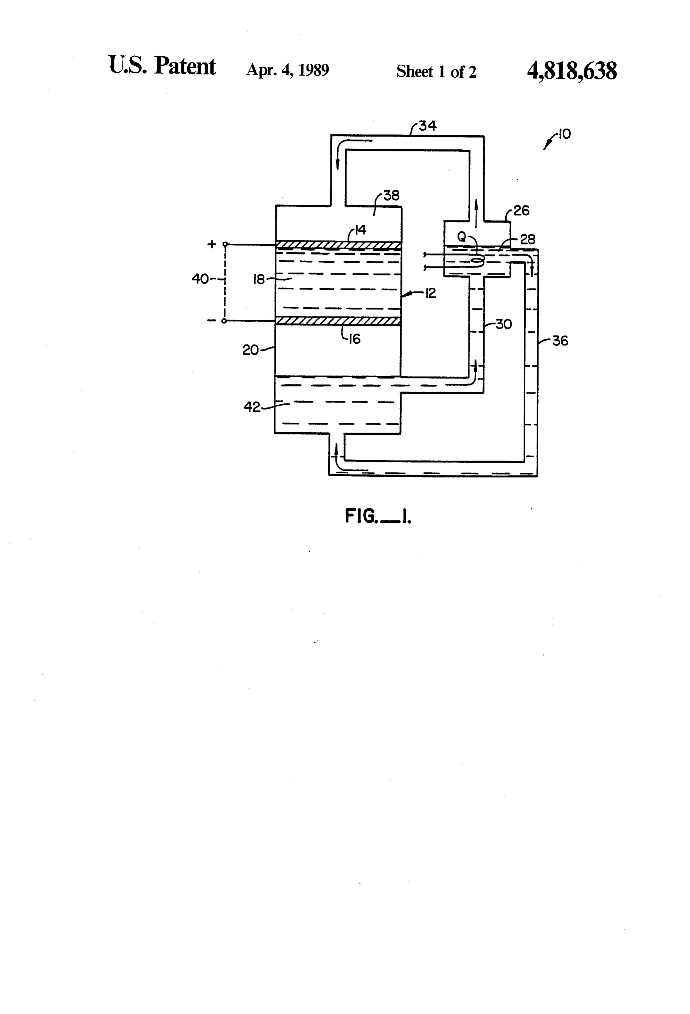
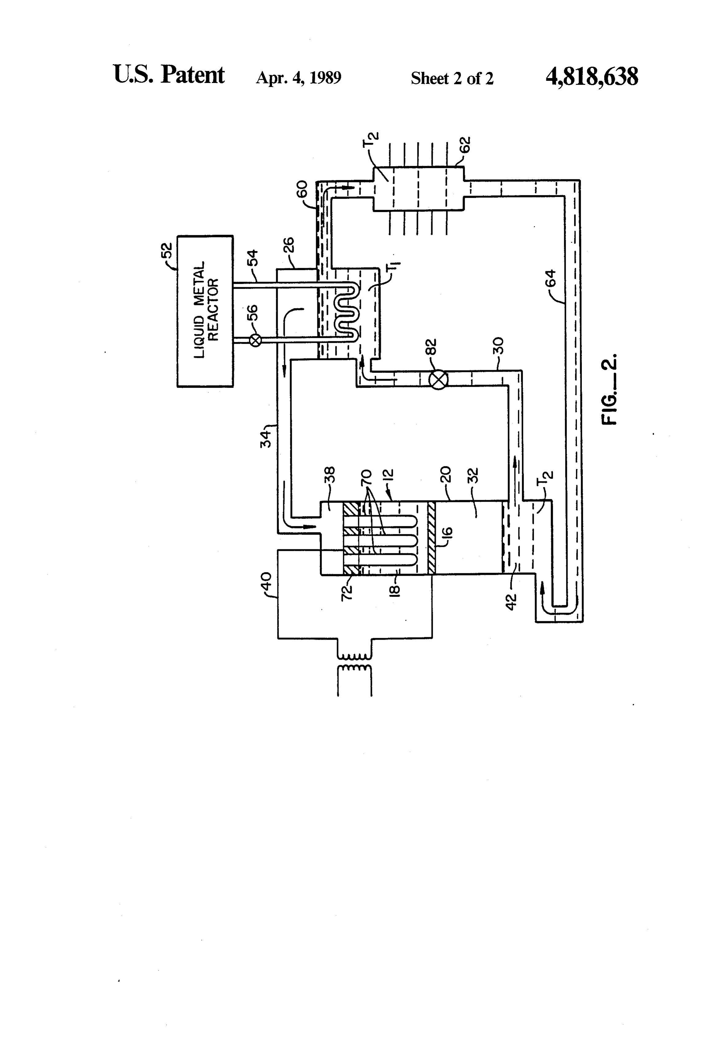
FIG. 1 is a flow chart illustrating the general opera decomposition vessel 26 receives a stream of molten tional principles of the present invention. 15 metal and metal hydride 28 through conduit 30 from a FIG. 2 is a flow chart illustrating a particular embodi lower chamber 32 in the vessel 20. The metal hydride 28 ment of the present invention. is thermally decomposed to hydrogen and molten DESCRIPTION OF THE PREFERRED metal. The hydrogen flows to vessel 20 through an EMBODIMENTS overhead conduit 34 while the molten metal returns to 20 the lower chamber 32 of vessel 20 through a lower
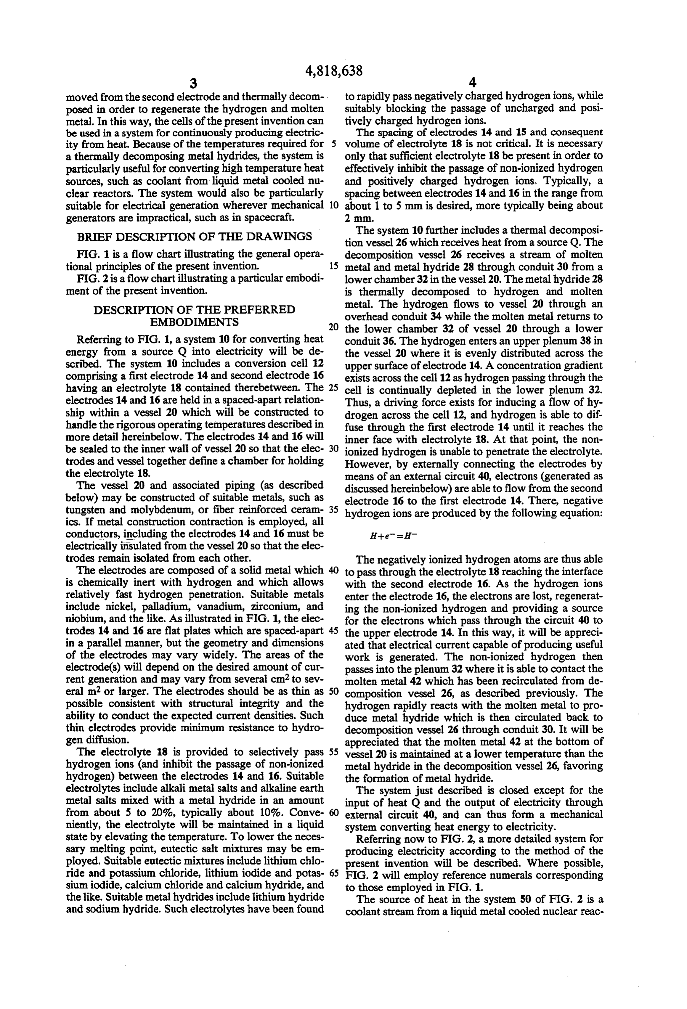
Referring to FIG. 1, a system 10 for converting heat conduit 36. The hydrogen enters an upper plenum 38 in energy from a source Q into electricity will be de the vessel 20 where it is evenly distributed across the scribed. The system 10 includes a conversion cell 12 upper surface of electrode 14. A concentration gradient comprising a first electrode 14 and second electrode 16 exists across the cell 12 as hydrogen passing through the having an electrolyte 18 contained therebetween. The 25 cell is continually depleted in the lower plenum 32. electrodes 14 and 16 are held in a spaced-apart relation Thus, a driving force exists for inducing a flow of hy ship within a vessel 20 which will be constructed to drogen across the cell 12, and hydrogen is able to dif handle the rigorous operating temperatures described in fuse through the first electrode 14 until it reaches the more detail hereinbelow. The electrodes 14 and 16 will inner face with electrolyte 18. At that point, the non be sealed to the inner wall of vessel 20 so that the elec 30 ionized hydrogen is unable to penetrate the electrolyte. trodes and vessel together define a chamber for holding However, by externally connecting the electrodes by the electrolyte 18. means of an external circuit 40, electrons (generated as The vessel 20 and associated piping (as described discussed hereinbelow) are able to flow from the second below) may be constructed of suitable metals, such as electrode 16 to the first electrode 14. There, negative tungsten and molybdenum, or fiber reinforced ceram 35 hydrogen ions are produced by the following equation: ics. If metal construction contraction is employed, all conductors, including the electrodes 14 and 16 must be electrically insulated from the vessel 20 so that the elec trodes remain isolated from each other. The negatively ionized hydrogen atoms are thus able The electrodes are composed of a solid metal which to pass through the electrolyte 18 reaching the interface is chemically inert with hydrogen and which allows with the second electrode 16. As the hydrogen ions relatively fast hydrogen penetration. Suitable metals enter the electrode 16, the electrons are lost, regenerat include nickel, palladium, vanadium, zirconium, and ing the non-ionized hydrogen and providing a source niobium, and the like. As illustrated in FIG. 1, the elec for the electrons which pass through the circuit 40 to trodes 14 and 16 are flat plates which are spaced-apart 45 the upper electrode 14. In this way, it will be appreci in a parallel manner, but the geometry and dimensions ated that electrical current capable of producing useful of the electrodes may vary widely. The areas of the work is generated. The non-ionized hydrogen then electrode(s) will depend on the desired amount of cur passes into the plenum 32 where it is able to contact the rent generation and may vary from several cm2 to sev molten metal 42 which has been recirculated from de eral m2 or larger. The electrodes should be as thin as 50 composition vessel 26, as described previously. The possible consistent with structural integrity and the hydrogen rapidly reacts with the molten metal to pro ability to conduct the expected current densities. Such duce metal hydride which is then circulated back to thin electrodes provide minimum resistance to hydro decomposition vessel 26 through conduit 30. It will be gen diffusion. appreciated that the molten metal 42 at the bottom of The electrolyte 18 is provided to selectively pass 55 vessel 20 is maintained at a lower temperature than the hydrogen ions (and inhibit the passage of non-ionized metal hydride in the decomposition vessel 26, favoring hydrogen) between the electrodes 14 and 16. Suitable the formation of metal hydride.
electrolytes include alkali metal salts and alkaline earth The system just described is closed except for the metal salts mixed with a metal hydride in an amount input of heat Q and the output of electricity through from about 5 to 20%, typically about 10%. Conve external circuit 40, and can thus form a mechanical niently, the electrolyte will be maintained in a liquid system converting heat energy to electricity. state by elevating the temperature. To lower the neces Referring now to FIG. 2, a more detailed system for sary melting point, eutectic salt mixtures may be em producing electricity according to the method of the ployed. Suitable eutectic mixtures include lithium chlo present invention will be described. Where possible, ride and potassium chloride, lithium iodide and potas 65 FIG. 2 will employ reference numerals corresponding sium iodide, calcium chloride and calcium hydride, and to those employed in FIG. 1.
the like. Suitable metal hydrides include lithium hydride The source of heat in the system 50 of FIG. 2 is a and sodium hydride. Such electrolytes have been found coolant stream from a liquid metal cooled nuclear reac
Page 6
tor 52. The coolant is pumped through an exchange that certain changes and modifications may be practiced conduit 54 by an electromagnetic pump 56. The decom within the scope of the appended claims. position vessel 26 will employ either LiH or an NaH as What is claimed is:
the metal hydride, depending on the temperature of the 1. A thermoelectric conversion cell comprising: liquid metal coolant employed. Typically, LiH will be a pair of spaced-apart solid electrodes having an elec employed for higher coolant temperatures in the range trolyte therebetween chosen to selectively pass from about 1000 to 1400 K, while NaH will be em ionized hydrogen atoms; ployed for lower coolant temperatures in the range means for supplying hydrogen gas to a first of said from about 600' to 1000 K. At the appropriate temper electrodes;
ature T1, the metal hydride will breakdown into hydro O means for supplying a reactant which reacts with gen, which passes through the overhead conduit 34 to hydrogen gas to a second of said electrodes so that vessel 20, and molten lithium or sodium, which passes a chemical potential created across the electrodes, through a conduit 60 to a heat exchanger 62. The heat whereby the flow of hydrogen across the elec exchanger 62 lowers the molten metal to a temperature trodes induces a current flow between the elec T2 where the metal may again combine with hydrogen 15 trodes.
to form a metal hydride. The cooled molten metal then 2. A cell as in claim 1, wherein the electrodes are passes through conduit 64 to the lower plenum 32 of composed of a solid metal selected from the group con vessel 20 where it is able to react with hydrogen passing sisting of nickel, palladium, vanadium, zirconium, and from the second electrode 16 of cell 12.
Hydrogen from decomposition vessel 26 passes to the 20 niobium.
upper plenum 38 of vessel 12 through conduit 38. 3. A cell as in claim 1, wherein the electrolyte is There, the hydrogen enters a plurality of tubular elec selected from the group consisting of a mixture of lith trodes 70 which extend downward from a support plate ium hydride and lithium chloride, and a mixture of 72. The tubular electrodes 70 are composed of the same calcium hydride and calcium chloride. materials described previously as suitable for elec 25 4. A cell as in claim 1, wherein the reactant is a mol trodes, and provide an increased electrode surface area ten metal which reacts with hydrogen to form a metal to enhance the permeation of the hydrogen into the hydride.
electrolyte 18 between the support plate 72 and second 5. A cell as in claim 4, wherein the means for supply electrode 16. As described before, the electrodes 70 are ing hydrogen gas comprises a means for thermally de isolated from electrode 16, but connected to electrode 30 composing the metal hydride formed by reaction of 16 through external circuit 40. As the hydrogen passes hydrogen and the molten metal, which means for ther through the tubular electrodes 70, the hydrogen atoms mally decomposing also supplies the molten metal. combine with electrons released from electrode 16. The 6. A thermoelectric conversion system comprising: negatively charged ions are able to migrate through the a cell including a pair of spaced-apart solid electrodes electrolyte 18 rapidly and arrive at electrode 16 where 35 having an electrolyte therebetween chosen to se the electrons are given up. The non-ionized hydrogen lectively pass ionized hydrogen atoms; entering plenum 32 through electrode 16 combines with an external circuit connecting the electrodes; the molten metal which is at the lower temperature T2. means for thermally decomposing a metal hydride The metal hydride is then pumped through conduit 30 into hydrogen gas and molten metal; by means of an electromagnetic pump 82 to decomposi means for directing the hydrogen gas to a first of said tion vessel 26 where it is again heated to temperature electrodes;
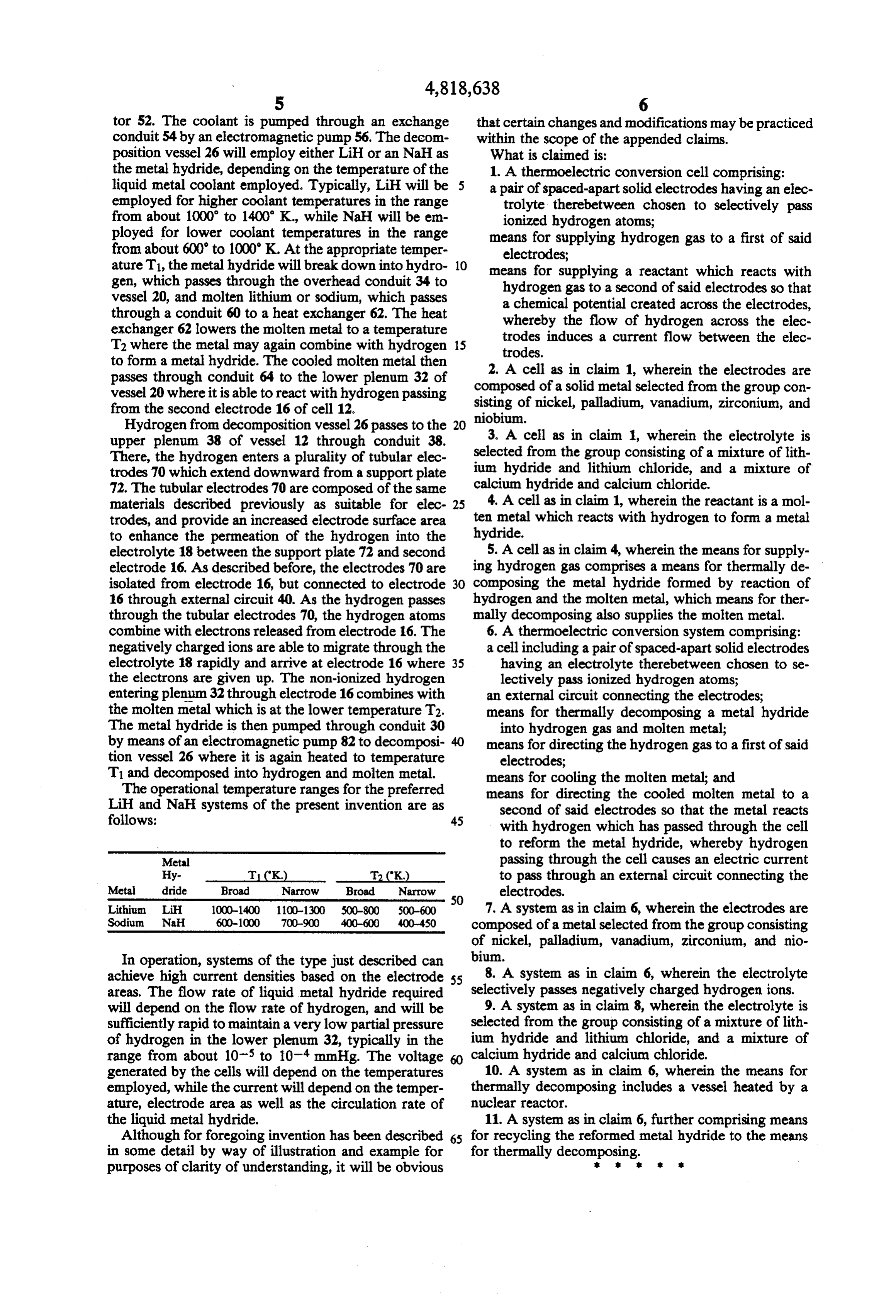
T1 and decomposed into hydrogen and molten metal. means for cooling the molten metal; and The operational temperature ranges for the preferred means for directing the cooled molten metal to a LiH and NaH systems of the present invention are as second of said electrodes so that the metal reacts follows: 45 with hydrogen which has passed through the cell to reform the metal hydride, whereby hydrogen
Metal passing through the cell causes an electric current Hy- T1 (K.) T2 (K.) to pass through an external circuit connecting the Meta dride Broad Narrow Broad Narrow
electrodes.
Lithium LiH 1000-1400 100-1300 500-800 500-600 7. A system as in claim 6, wherein the electrodes are Sodium NaH 600-1000 700-900 400-600 400-450 composed of a metal selected from the group consisting of nickel, palladium, vanadium, zirconium, and nio
In operation, systems of the type just described can bium.
achieve high current densities based on the electrode 55 8. A system as in claim 6, wherein the electrolyte areas. The flow rate of liquid metal hydride required selectively passes negatively charged hydrogen ions. will depend on the flow rate of hydrogen, and will be 9. A system as in claim 8, wherein the electrolyte is sufficiently rapid to maintain a very low partial pressure selected from the group consisting of a mixture of lith of hydrogen in the lower plenum 32, typically in the ium hydride and lithium chloride, and a mixture of range from about 10-5 to 10 mmHg. The voltage calcium hydride and calcium chloride.
generated by the cells will depend on the temperatures 10. A system as in claim 6, wherein the means for employed, while the current will depend on the temper thermally decomposing includes a vessel heated by a ature, electrode area as well as the circulation rate of nuclear reactor.
the liquid metal hydride. 11. A system as in claim 6, further comprising means Although for foregoing invention has been described 65 for recycling the reformed metal hydride to the means in some detail by way of illustration and example for for thermally decomposing.s purposes of clarity of understanding, it will be obvious
Provenance
- Collection
- Cited prior art
- Original PDF
- patentimages.storage.googleapis.com →
- Filed
- 1987-06-09
- Pages
- 6
- Method
- pdftotext (the PDF's own text layer) + pdftoppm 300dpi page scans
- Source
- Google Patents bibliographic record
- Granted
- 1989-04-04
- Inventors
- Prodyot Roy; General Electric Co
- Transcribed from
- patentimages.storage.googleapis.com →