patent · US4211828
Thermoelectric energy system
8 July 1980
Page 1 — bibliographic record
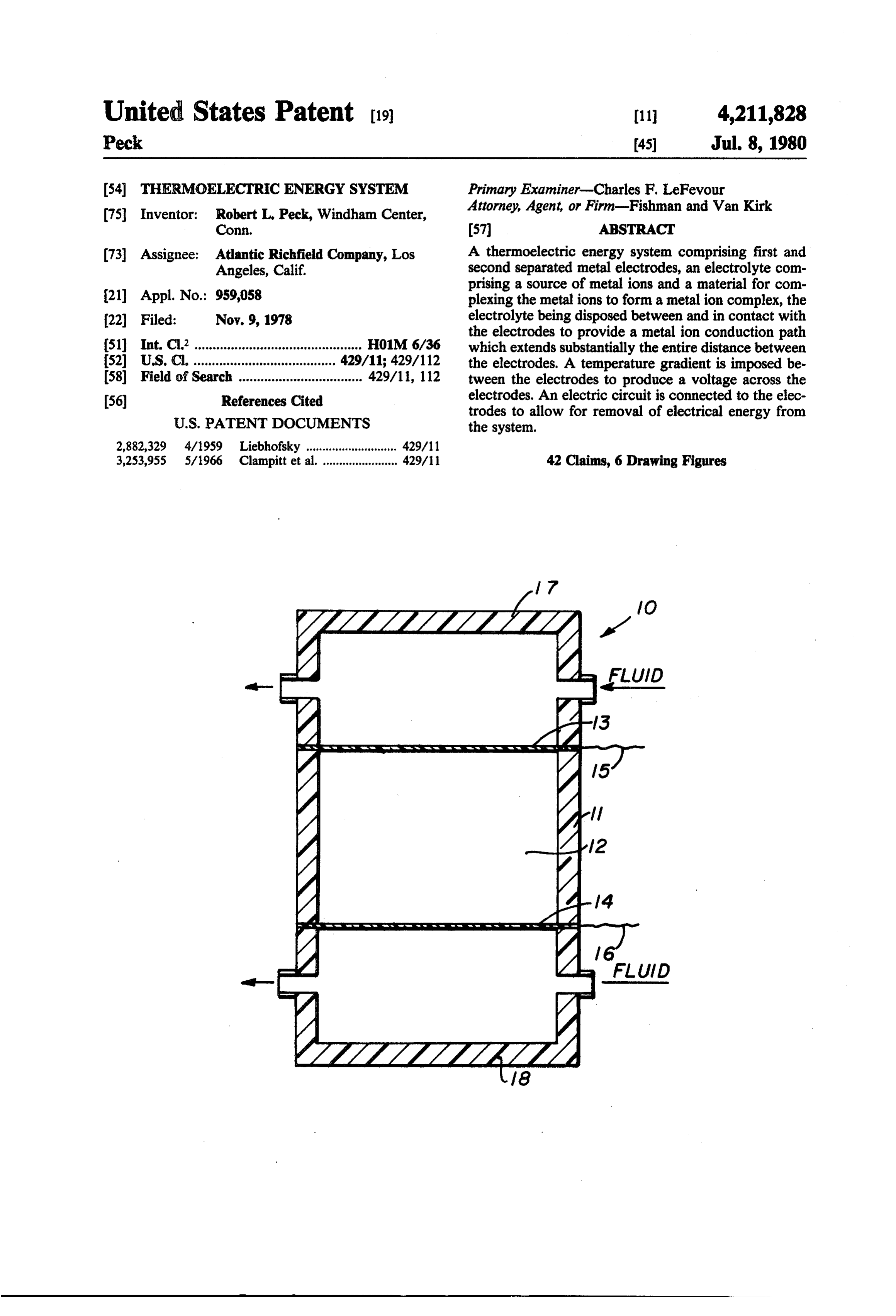
United States Patent (19) 11 4,211,828 Peck (45) Jul. 8, 1980 (54) THERMOELECTRIC ENERGY SYSTEM Primary Examiner-Charles F. LeFevour (75 Inventor: Robert L. Peck, Windham Center, Attorney, Agent, or Firm-Fishman and Van Kirk Conn. 57 ABSTRACT 73) Assignee: Atlantic Richfield Company, Los A thermoelectric energy system comprising first and Angeles, Calif. second separated metal electrodes, an electrolyte com prising a source of metal ions and a material for com (21) Appl. No.: 959,058 plexing the metal ions to form a metalion complex, the (22 Filed: Nov. 9, 1978 electrolyte being disposed between and in contact with the electrodes to provide a metal ion conduction path 51 int. C.’.............................................. HOM 6/36 which extends substantially the entire distance between 52 U.S. C. ............................... ... 429/11; 429/112 the electrodes. A temperature gradient is imposed be 58) Field of Search .................................. 429/11, 112 tween the electrodes to produce a voltage across the (56) References Cited electrodes. An electric circuit is connected to the elec
trodes to allow for removal of electrical energy from the system.
2,882,329 4/1959 Liebhofsky ............................ 429/11 3,253,955 5/1966 Clampitt et al. ....................... 429/11 42 Claims, 6 Drawing Figures
s sa A. S. W. a...Y sa & as s s w w s
3. ZZZZZZZZZZZZ
Page 2
Drawing sheet — no readable text.
Page 3
Drawing sheet — no readable text.
Page 4
9O Ex. 9 o CuSO4 - TA 8O Ex... O Cu(BF4)2+TA 7O Ex. x CuSO4 + EDTA 6O Ex. 2 (2) Cu(BF4)2 + EDTA
MARKS MAX. POWER PONT
. .. 2 3- 4 5 ,6 .789 | 2 3 4 5 6 7 89 IO Log - Log Plot of Ri vs I
Page 5
eliminates corrosion, pitting, scaling or uneven dissolu
THERMOELECTRIC ENERGY SYSTEM tion of electrodes in the system. It is another object of the present invention to pro
BACKGROUND OF THE INVENTION vide a thermoelectric energy system which can be oper (1) Field of the Invention ated without frequent replacement of the electrodes and
The invention relates to thermoelectric energy sys frequent replenishment of the electrolyte.
tems which convert thermal energy into electrical en polarization It is another object of the present invention to reduce occurring during operation of the thermo ergy. More particularly, the invention relates to a ther electric energy system.
moelectric apparatus and a method for converting ther 10 It is still another object of the present invention to mal energy to electrical energy. provide athermoelectric energy system which provides (2) Description of the Prior Art
It is known that electrical power can be produced aover relatively constant current through a constant load a relatively long period of time.
from a thermoelectric cell comprising an electrolyte disposed between two metal electrodes. One type of 15 SUMMARY OF THE INVENTION thermoelectric cell is disclosed in U.S. Pat. No. The thermoelectric energy system of the present 3,253,955. This patent discloses an apparatus for obtain invention includes a thermoelectric cell comprising at ing electrical energy from heat energy. One thermo least a first and a second separated metal electrode and electric cell disclosed in this patent comprises a con a liquid electrolyte comprising a source of metal ions tainer which is divided into chambers or compartments. 20 and a material for complexing the metal ions to form a An ion bridge is positioned between the two chambers metal ion complex, the electrolyte being disposed be and copper electrodes are positioned within each cham tween and in contact with the electrodes to provide a ber. Each container is filled with an aqueous copper metal ion conduction path which extends substantially sulfate electrolyte. An aperture is provided between the the entire distance between the electrodes. A tempera chambers and an ion bridge is mounted in the aperture. 25 ture differential or gradient is imposed between the It is stated that the ion bridge can be a sintered glassion electrodes to produce a voltage across the electrodes. bridge, a porous disc, a salt bridge, an agar-agar salt An electrical circuit is connected to the electrodes to bridge, an ion permeable membrane, pure difusion (no allow for removal of electrical energy from the cell. separation), or other suitable types of bridges known to One particularly novel aspect of the system of the pres the art. This patent also states that the cell is reversible, 30 ent invention is to provide an electrolyte wherein the that is, the temperature differential of the cell can be electrolyte includes a material for complexing the metal reversed to provide for movement of the copper ions in ions to thereby form a metal ion complex. a reverse direction. In the preferred embodiment of the invention, the A second type of thermoelectric cell is disclosed in electrodes comprise two metallic copper electrodes and Electrolyte Thermal Piles, Vesz Pren, Hungary (1971), 35 the electrolyte comprises a source of copper metalions, Vol. 1, Hoffman and David. This article discloses a the source being, for example, copper sulfate or copper thermoelectric cell comprising an aqueous copper sul fluoroborate. The complexing agent for the copper ions fate electrolyte disposed between two metallic copper can be selected from any number of conventional cop electrodes. A temperature differential is imposed be per ion complexing agents such as tartrates, tween the electrodes by heating one electrode and al ethylenediaminetetracetic acid and/or gluconates. In lowing the other electrode to remain at room tempera addition or as a substitute for the above-described con ture. A potential difference and a current can be mea ventional copper ion complexing agents, the material sured between the two copper electrodes. As the tem for complexing the copper ion may be a silica gel, or perature differential is applied to the copper electrodes powder.
and the cell begins to generate power, the electrodes 45 One important advantage of the thermoelectric en may become caked or scaled so as to inhibit the further ergy system of the present invention is that the system is generation of power. capable of providing a relatively constant current Moreover, a cell of the type disclosed by Hoffmann across a load. It is also believed that the inclusion of a and David has another drawback. When the tempera complexing material for the metalions reduces or elimi ture difference is applied to the electrodes in the elec 50 nates the polarization occurring between the electrodes trolyte, the current output through a constant load and the electrolyte. Furthermore, the formation of cak decays over a period of time. It is believed that this ing or scaling on the electrodes is reduced or elimi decay in current output is caused by polarization occur nated: in thermoelectric cells according to the present ring between the electrodes within the electrolyte and invention, a smooth, matted surface is maintained on /or by formation of caking or scaling such as oxides or 55 each of the electrodes as the cell produces power in sulfates. response to a temperature differential imposed between Another type of cell is disclosed in U.S. Pat. No. the electrodes.
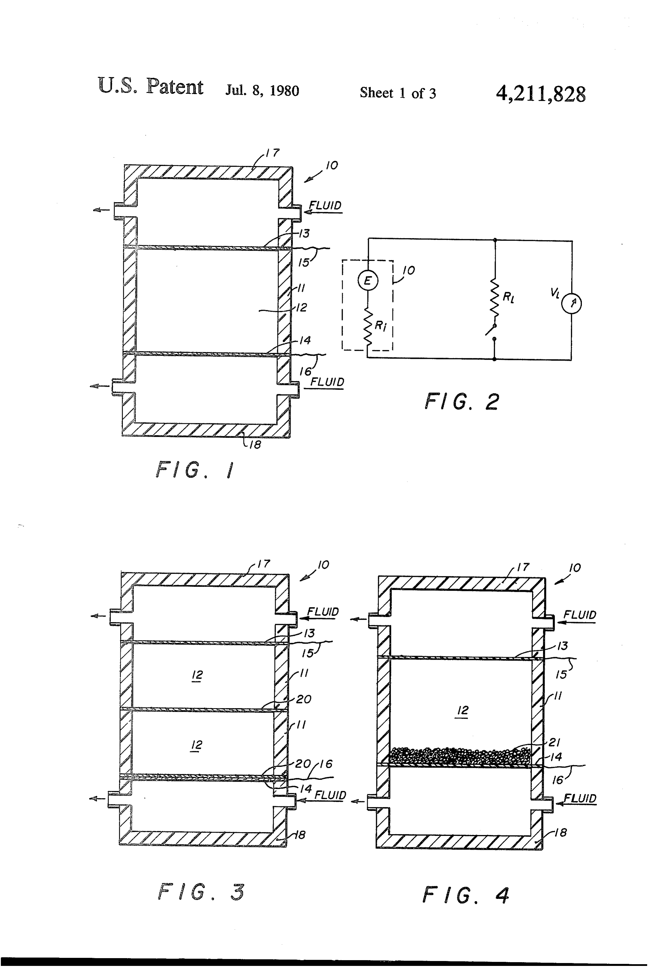
2,882,329. This cell comprises two electrodes of the BRIEF DESCRIPTION OF THE DRAWING same composition separated by a cation permeable ex change resin membrane which is said to be the sole 60 FIG. 1 is a schematic side sectional view of a thermo electrolyte in direct contact with the electrodes. This electric cell;
patent teaches that aqueous electrolytes should not be FIG. 2 is a schematic view of circuitry for testing used in the cell. thermoelectric cells;
It is an object of the present invention to provide a FIG. 3 is a schematic side sectional view of a thermo thermoelectric energy system having a relatively high 65 electric cell including convection barrier membranes; power output. FIG. 4 is a schematic side sectional view of a thermo It is another object of the present invention to pro electric cell including an amorphous silica convection vide a thermoelectric energy system which reduces or barrier;
Page 6
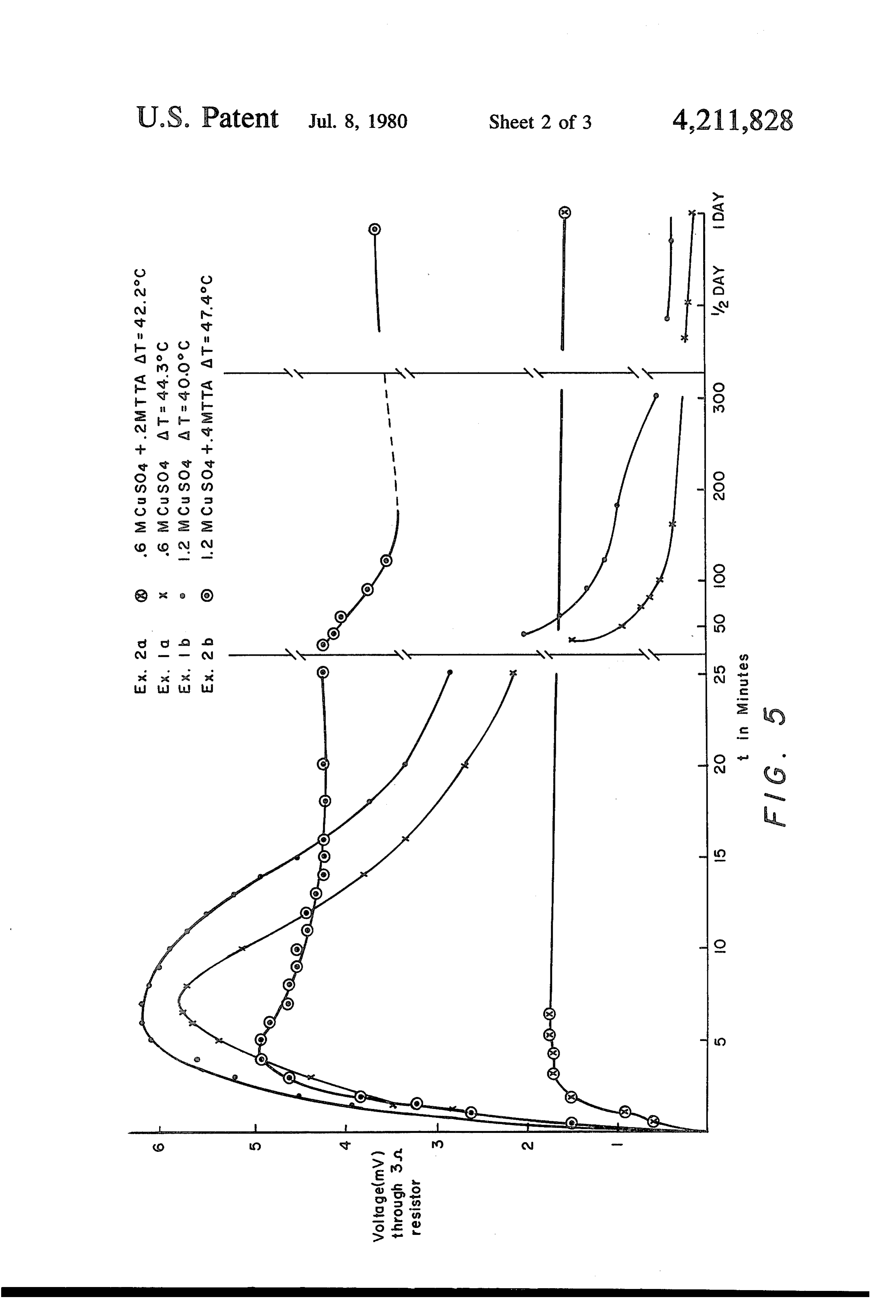
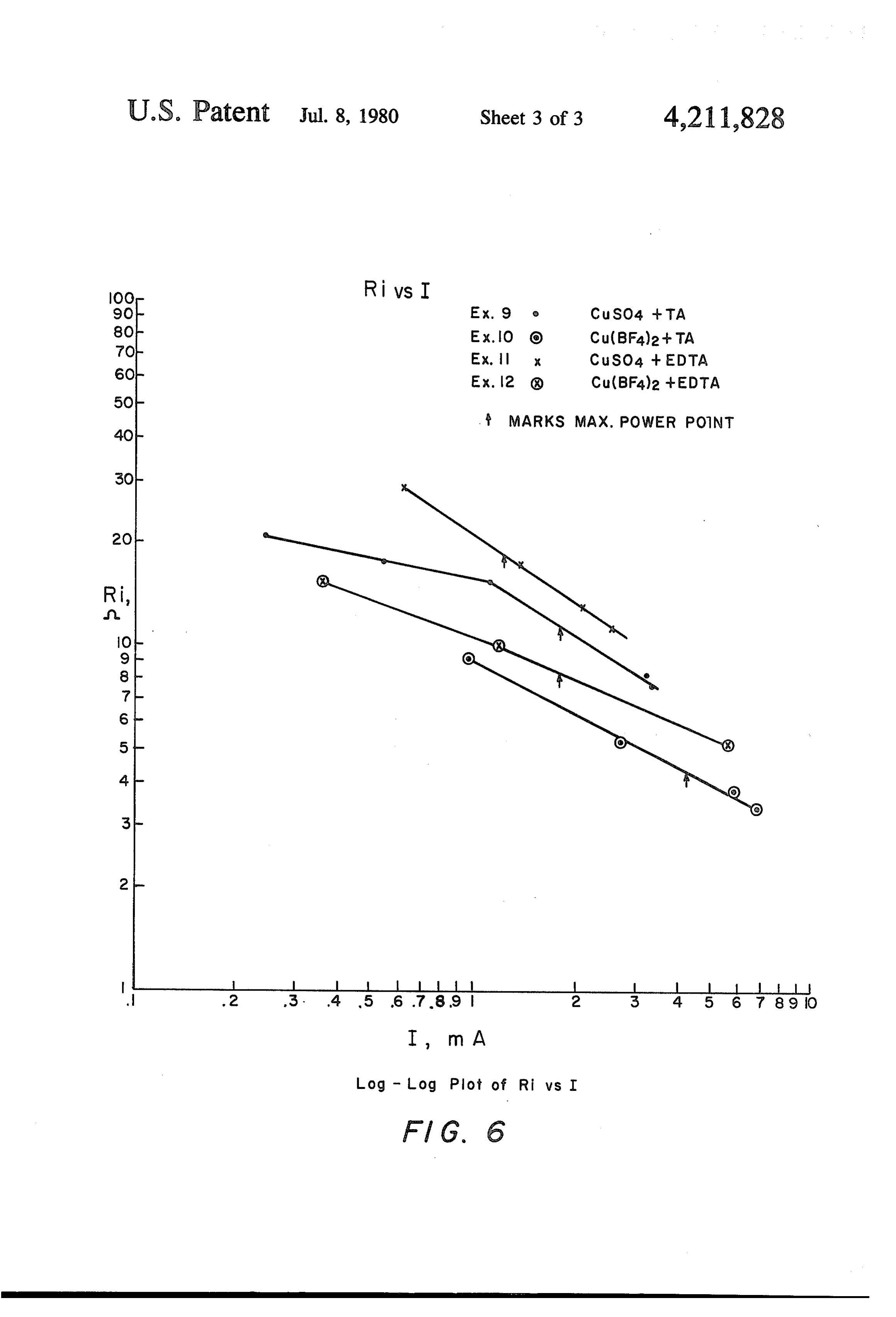
FIG. 5 is a plot of voltage v. time of a cell tested in and plated on the second electrode, the thermal gradi accordance with Examples 1 and 2; and ent within the electrolyte can be reversed with the same F.G. 6 is a plot of the log of the internal resistance v. current density thus reversing the direction of the mass the log of the current in accordance with Examples 9, flow of metal ions.
10, 11 and 12. It should be understood that the cell of the present DETAILED DESCRIPTION OF THE invention can run almost indefinitely as long as the temperature gradient within the electrolyte is reversed
INVENTION periodically to maintain both electrodes within a de FIG. 1 is a schematic diagram of a thermoelectric sired weight and surface area. Thus, as shown in F.G. , energy system of the present invention. Cell 10 com 10 initially, heat transfer chamber 18 has relatively warm prises a container 11 which is preferably made from a or hot fluid flowing therethrough and heat transfer material which does not react to a significant degree chamber 17 has relatively cool heat transfer fluid flow with the liquid electrolyte 12 disposed within container ing therethrough. As the process continues, and elec 11. Container 11 is preferably made from glass or teflon. trode 13 dissolves, the flow of fluid through heat trans Electrodes 13 and 14 are positioned in contact with 15 fer chambers 17 and 18 can be reversed so as to reverse electrolyte 12. Conductive electric wires 15 and 16 are the flow of metal ions. In another embodiment of the connected respectively to electrodes 13 and 14 and invention the consumed electrode is replaced periodi provide for removal from cell 10 of electric power cally thus avoiding the necessity of reversing the tem generated by the cell. Although as shown in the sche perature gradient within the electrolyte. matic diagram, the electrodes 13 and 14 are coplanar, in 20 The temperature gradient within the electrolyte can practice, the electrodes may have any geometry or be maintained by any conventional method. For exam orientation provided they are separated from each other ple, one side of the cell can be maintained at room tem by the electrolyte. Mounted on either side of electrodes perature while the other side is cooled. It is believed 13 and 14 are heat transfer chambers 17 and 18 through that the present invention has utility for converting which fluid may be circulated to either cool or heat 25 waste heat from electric utility plants into electrical electrodes 13 and 14 and provide a temperature differ energy and converting heat produced by solar energy ential within electrolyte 12. It should be understood into electrical energy. Rather than producing electrical that any apparatus which allows for the provision of a energy for external use from the thermoelectric energy temperature differential between electrodes disposed system, the temperature gradient may be used in an within the electrolyte may be used. The schematic dia 30 electroplating process wherein metal from one elec gram shown in FIG. 1 is merely one example of numer trode is transferred to the object it is desired to plate. In ous constructions that could be used in connection with electroplating, the utilization of a temperature differen the present invention. When a temperature differential tial reduces power requirements for the electroplating is imposed between electrodes 13 and 14, an emf is process. The thermoelectric system may possibly be developed between the electrodes, the emf being a func 35 used in the electrowinning of metals, particularly the tion to the temperature gradient. electrowinning of copper.
One surprising and unexpected result achieved by the Generally speaking, the voltage of the cell is propor system of the present invention is the provision of a cell tional to the temperature difference when the cell is in which the formation of caking or scaling on the elec connected across a constant electrical load, so that, trodes is reduced or eliminated. During the generation even the slightest temperature differential will produce of power and the transference of metal from one elec a current. However, since this invention is directed to a trode to the other electrode, a smooth, matted surface is thermoelectric device for producing useful amounts of maintained on each of the electrodes. current, to obtain increased output of current, it is pre In the preferred embodiment of the cell of the present ferred to operate the hot electrode above 60 Celsius, invention, during the functioning of the energy cell 45 and operate with a temperature differential between the substantially all of the metal that is dissolved from one electrodes of at least 30° Celsius. The temperature of the electrode is deposited on the second electrode so that lower temperature electrode should be determined by during transference of the metal, a relatively constant the ion concentration in the electrolyte, and the combi current is maintained. Another surprising and unex nation of the lower temperature and the ion concentra pected result is that during the functioning of the pre 50 tion should not result in the precipitating of salts out of ferred energy cell of the present invention, the chemical the electrolyte to a degree which would impede the composition of the electrolyte is maintained. Restated, generation of power. In general, when the temperature during the operation of the preferred cell of the present range is known, then the ion concentration in the elec invention, the ions migrate through the electrolyte, trolyte may be determined so that salts will not crystal deposit on the second electrode and the concentration 55 lize or precipitate out at the lower temperature. of ions and other chemicals in the electrolyte is main The electrodes can be made of different metals or the tained. This functioning of the cell has important eco electrodes can be made from the same metal. Although nomic consequences. Firstly, the cell of the present the system of the present invention may possibly func invention is capable of providing a relatively constant tion when electrodes comprise alloyed metals, it is most current. Secondly, the electrolyte can be maintained in preferable that the electrodes comprise elemental or the cell almost indefinitely without net chemical pure metals. The electrolyte must include a compound changes in its composition. It should be understood that which provides a source of metal ions of the type de as the preferred cell functions, the mass of one electrode sired to be transferred through the electrolyte. The may become depleted so that if the cell is allowed to electrolyte must also include a material which forms run, the entire mass of the electrode will be dissolved 65 loose bonds with the metal ions in the electrolyte to and plated on the second electrode and the ability of the provide a metal ion complex which provides for con cell to produce electrical energy will cease. However, duction channels for charge transfer. The metal ion after a predetermined mass of one electrode is dissolved complex formed is believed to extend between the elec
Page 7
trodes and to provide a flow path for the metal ions. It can be adjusted by an acid which does not corrode the should be understood that it is possible, and in some electrodes or which does not have substantial adverse instances desirable, for the concentration of the metal affects on the ability of the electrolyte to transfer metal ion complex to vary between the electrodes. ions. When the cells have elemental copper electrodes, In the most preferred form of the present invention it is preferred that sulfuric acid be used as a pH adjuster the electrodes comprise copper plates which are spaced with copper sulfate salts and fluoroboric acid with cop apart by an electrolyte including a source of copper ions per fluoroborate salts. Although it is preferred that an and a source of complexing material for the copper ions. aqueous electrolyte be used, it is envisioned that organic Preferred sources of copper ions are copper salts such solvents such as, for example, pyridine may be used in as copper fluoroborate and/or copper sulfate. 10 the apparatus and method of the present invention to Examples of copper ion complexing agents are, for provide a liquid electrolyte.
example, sources of tartrate, ethylenediaminetetracetic It should be understood that the power output of the acid (EDTA), and/or gluconate. Preferred sources of thermoelectric energy system is dependent upon many tartrate include any one of a mixture of tartaric acid, the variables such as, for example, the temperature differen Rochelle salt of tartaric acid and cream of tartar. 5 tial, the size of the electrodes, the composition of the Sources of EDTA include any one or a mixture of electrodes, the composition of the electrolyte, the space ethylenediaminetetracetic acid, ethylenediaminetetra between the electrodes, and the electrical resistance of cetic acid calcium disodium chelate, the electrolyte. The power efficiency of a cell of the ethylenediaminetetraetic acid sodium salt, present invention is, as a general rule, proportional to ethylenediaminetetracetic acid tetrasodium salt and 20 the heat conduction through the electrolyte. If, for ethylenediaminetetracetic acid trisodium salt. A pre example, the electrodes are located closely together so ferred source of gluconate is gluconic acid. It should be that the internal electrical conductance is raised, the understood that any complexing agent may be used electrical power output is increased. However, by posi which complexes the ion to be transferred through the tioning the electrodes closely together, heat conduction electrolyte and which allows for dissolution of metal 25 is also increased. The resulting heat flow results in a ions from one electrode into the electrolyte and deposi decrease in the power efficiency. Thus, as should be tion of metal ions on the second electrode. Although it understood by one skilled in the art, the design of any is believed that they provide low metal ion transfer, given cell can be based upon knowledge of this compro complexing agents such as lactic, malic, citric and ox mise. The power efficiency of the cell can be increased alic acids may have utility in some applications. It is 30 by reducing the thermal conductivity by use of thermal preferred that the complexing compound be added to the electrolyte so that the weight ratio of complexing barriers tion which decrease conduction of heat by convec currents. Efficiency of the cell of the present inven ions to copper ions is between about 0.01 to about 10.
A preferred electrolyte comprises about one weight divided by theasheat tion is defined the electrical energy put out by the cell percent to saturation of copper sulfate or copper fluoro 35 As was mentionedenergy into the cell. earlier, the prior art cells are be borate or a mixture thereof and about 1 weight percent lieved to have polarization problems to saturation of tartaric acid. A particularly preferred scale and caking on the electrodes. Aand buildup of surprising and electrolyte includes about 10 to about 45 weight percent unexpected result obtained with the use of the present copper sulfate and about 1 to about 30 weight percent cell is that the polarization problem is reduced and the tartaric acid and a second particularly preferred electro internal resistance of the cell of the present invention lyte includes about 10 to about 50 weight percent cop perfluoroborate and about 1 to about 30 weight percent decreases as the current through the cell increases. The manner in which the internal resistance of the cell is tartaric acid.
A characteristic that is common with the above-men measured can best be explained by reference to FIG. 2. tioned complexing agents is that the metal ions com the 45
When a temperature gradientis imposed within the cell, cell generates an emf designated as E and has inter plexed in the electrolyte extend substantially the entire nal resistance conduction path between the electrodes. The metal ion a load such asdesignated a resistor as R. The cell is connected to designated as RL and the volt complexes appear to function as exchange matrices, that age across the resistor VL can be measured with a volt is, they absorb the metal ions without irreversible chem meter. The following is a derivation of the value ical bonding. Thus, the electrolyte contains a metal ion SO internal resistance of the cell. VL is the voltage for the absorbing or complexing material which extends sub the resistor RL when the circuit is closed. E is theacross open stantially the entire conduction path between the elec circuit voltage and I is the current through the external trodes. The complexing material may comprise the circuit.
conventional metal ion complexing agents dissolved in solution as set forth above. As an alternative, the ab 55 sorbing or complexing material may comprise a silica gel or powder which is added to the electrolyte. The E= I (R-RI) silica (SiO2) may be the sole complexing material used in the cell or the silica may be mixed with the metal ion Another important property of the system of the complexing agents previously discussed. present invention is that the internal resistance of the Although it has been determined that a current out cell decreases, as the current through the cell increases. put is provided by a cell having an electrolyte having a It is difficult to maintain the temperature differential pH which is basic, it is preferred that the pH of the in the electrolyte because convection currents tend to electrolyte be acidic. It has been found that as a general develop in the electrolyte and reduce the temperature rule, the current output of the cell increases as the elec 65 differential. As shown in FIG. 3, convection barriers 20 trolyte becomes more acidic. It is particularly preferred are inserted between the electrodes. The use of thermal that the pH of the electrolyte be below about 5 and most convection barriers reduce the amount of heat transfer preferably below about 2.0. The pH of the electrolyte occurring in the electrolyte while maintaining the con
Page 8
ductance of the electrolyte. Convection barriers 20 when current is attributed solely to the transfer of metal allow for the free migration of copper ions from one ions:
electrode to the other and provide thermal insulation between the electrodes while not substantially increas W M.Wt.
ing the resistance between the electrodes. The barriers calculated - Valence x 96.500 o Idf shown in FIG. 3 comprise a thin membrane. One or more barriers may be used and the barriers may be Where calculated is the weight in grams gained or located adjacent the electrode or spaced between the electrodes. The convection barriers 20 as shown in lost by an electrode. M.Wt. is the molecular weight of FIG. 3 are made of a perfluorosulfonic acid membrane O the metal transferred, Valence is the valence of the such as that sold by DuPont de Nemours and Company time metal transferred, I is the current in amperes, and t is under the trademark NAFION. A similar material may in seconds.
be used such as the polyox-phenolic polymer disclosed and the In the case of copper, the molecular weight is 63.54 in U.S. Pat. No. 3,883,784 by Peck et al. valence is 2. In order to calculate the amount of Another embodiment of a convection barrier is 15 current flowing from the cell due to the flow of metal shown in FIG. 4. The convection barrier comprises fine ions, the plating percentage is calculated which is de particles of amorphous silica 21. Th silica functions in a fined as the actual weight deposited divided by the manner similar to the membrane in that it reduces con weight that would have been deposited if the current vection within the electrolyte while maintaining the was solely a result of metal ion transfer. Thus, in the conductance of the electrolyte between the electrodes. 20 case of copper the plating percentage is calculated as It should be understood that, in general, the convection follows:
barrier comprises a physical obstruction which reduces convection in the electrolyte and which provides an Plating Percentage = ionic path for the metal ions. Other types of convection Weight gained or lost X 1.845 (ampere:hrs) %
barriers such as, for example, porous glass, ceramics 25 Idt (ampere-hrs) such as alumina, Bentonite, glass wool and the like may o be used. In the case of a copper containing electrolyte, when the complexing agent is added to the copper salts, It should be understood that a plating percentage of a precipitate may be produced. For example, when less than 100% indicates that the cell has generated copper sulfate and tartaric acid are combined and 30 more current than can be accounted for by the transport heated over a period of time, a precipitate may be of metal ions of that valence between the electrodes. formed. The precipitate may or may not be removed. In This result indicates that some other mechanism in addi some instances, it is desirable to leave the precipitate in tion to the transport of metal ions of that valence be the electrolyte to provide a convection barrier. tween the electrodes is responsible for a portion of the It should be understood that the space between the 35 current produced by the cell. Thus, in some instances, electrodes can contain material in addition to the elec the plating percentages may possibly be reduced to near trolyte. More specifically, a matrix saturated with elec 0% so that none of the current is attributable to the trolyte may be used. Such matrices should allow for transfer of metal ions between the electrodes according transference of metal ions therethrough and can com to Faraday's Law.
prise an inorganic material such as porous ceramics or The electrolyte is prepared by dissolving the metal an organic material such as polymeric matrices includ salt and the complexing agent separately in distilled ing polytetrafluoroethylene. It should be understood water which is heated and stirred. The mixture of the that there are many known matrices which can be in two solutions is heated and stirred for several hours serted between the electrodes. during which time a powdery pale blue precipitate As shown in FIG. 2, the output of the thermoelectric 45 forms which settles slowly when the stirring is stopped. energy cell was determined by measuring the voltage The precipitate which is formed when preparing the VL, across a predetermined load resistance, Ri, which electrolyte may be included in the electrolyte used in was connected to the electrical outputs of the cell. The the cell in order to promote plating. Cells that utilize an surprising and unexpected result obtained by the cell of electrolyte containing only the liquid part of the elec the present invention is that the current through a load 50 trolyte with no precipitate, in general, have plating is maintained or slightly increased over a period of time. percentages less than about 25%. When a precipitate is This current output remains relatively constant until the included in the electrolyte used in the cell, the plating surface area of one of the copper electrodes is reduced percentage rises and may approach 100%. substantially by dissolution. It should be understood The following examples are illustrative of thermo that in prior art cells the electrolyte is polarized and 55 electric results in decay of the current produced by the cell. tion. energy systems according to the present inven With the cell of the present invention, the polarization effect is reduced and a cell is provided that can produce EXAMPLES a relatively constant current. EXAMPLES 1 AND 2 As stated earlier, metal dissolves from the cold elec trode and plates onto the hot electrode, but the plating The following examples were run in a test cell con percentage can vary. The plating percentage at either structed of Teflon including two electrodes made from the hot or cold electrode is defined as the weight electrolytically refined copper. The spacing between change of the electrode divided by the weight change the electrodes was 1.91 cm and the area of each elec one would expect if all of the current through the cell 65 trode was 8.1 cm2. The cool electrode was cooled by over a period of time had been carried only by metal water at approximately 25 C. and the hot electrode was ions in accordance with Faraday's Law. According to heated by contacting the hot electrode with heated oil Faraday's Law, the following equation should be met to provide a temperature differential as indicated in
Page 9
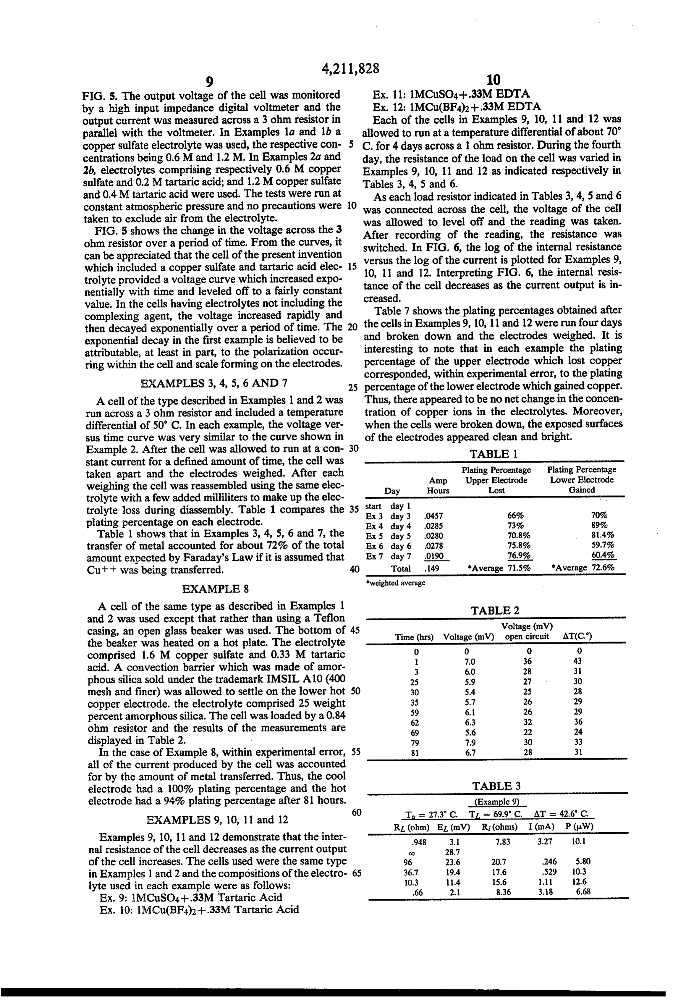
FIG. 5. The output voltage of the cell was monitored Ex. 11: 1MCuSO4--.33M EDTA by a high input impedance digital voltmeter and the Ex. 12: 1MCu(BF4)2+.33M EDTA output current was measured across a 3 ohm resistor in Each of the cells in Examples 9, 10, 11 and 12 was parallel with the voltmeter. In Examples 1a and lb a allowed to run at a temperature differential of about 70 copper sulfate electrolyte was used, the respective con C. for 4 days across a 1 ohm resistor. During the fourth centrations being 0.6M and 1.2M. In Examples 2a and day, the resistance of the load on the cell was varied in 2b, electrolytes comprising respectively 0.6M copper Examples 9, 10, 11 and 12 as indicated respectively in sulfate and 0.2 Mtartaric acid; and 1.2M copper sulfate Tables 3, 4, 5 and 6.
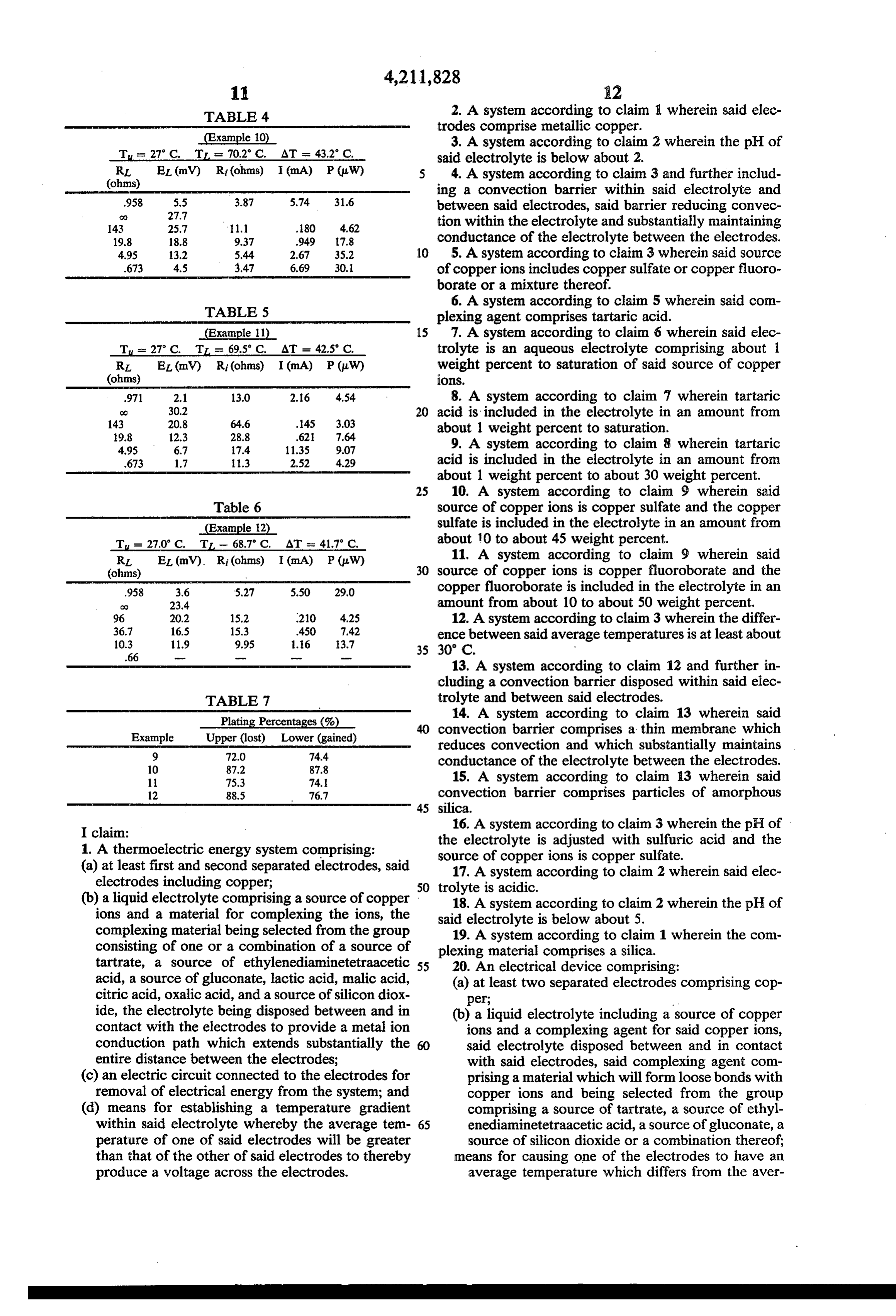
and 0.4 Mtartaric acid were used. The tests were run at As each load resistor indicated in Tables 3, 4, 5 and 6 constant atmospheric pressure and no precautions were 10 was connected across the cell, the voltage of the cell taken to exclude air from the electrolyte. was allowed to level off and the reading was taken. FIG. 5 shows the change in the voltage across the 3 After recording of the reading, the resistance was ohm resistor over a period of time. From the curves, it switched. In FIG. 6, the log of the internal resistance can be appreciated that the cell of the present invention which included a copper sulfate and tartaric acid elec 15 versus the log of the current is plotted for Examples 9, trolyte provided a voltage curve which increased expo tance of the12.cellInterpreting
decreases
FIG. 6, the internal resis as the current output is in nentially with time and leveled off to a fairly constant creased.
value. In the cells having electrolytes not including the complexing agent, the voltage increased rapidly and theTable 7 shows the plating percentages obtained after then decayed exponentially over a period of time. The 20 cells in Examples 9, 10, 11 and 12 were run four days exponential decay in the first example is believed to be and broken down and the electrodes weighed. It is attributable, at least in part, to the polarization occur interesting to note that in each example the plating ring within the cell and scale forming on the electrodes. percentage of the upper electrode which lost copper corresponded, within experimental error, to the plating
EXAMPLES 3, 4, 5, 6 AND 7 25 percentage of the lower electrode which gained copper.
A cell of the type described in Examples 1 and 2 was Thus, there appeared to be no net change in the concen run across a 3 ohm resistor and included a temperature tration of copper ions in the electrolytes. Moreover, differential of 50° C. In each example, the voltage ver when the cells were broken down, the exposed surfaces sus time curve was very similar to the curve shown in of the electrodes appeared clean and bright.
Example 2. After the cell was allowed to run at a con 30 TABLE 1. stant current for a defined amount of time, the cell was Plating Percentage Plating Percentage taken apart and the electrodes weighed. After each Amp Upper Electrode Lower Electrode weighing the cell was reassembled using the same elec Day Hours Lost Gained trolyte with a few added milliliters to make up the elec start day 1 trolyte loss during diassembly. Table 1 compares the 35 Ex 3 day 3 0457 66% 70% plating percentage on each electrode. Ex 4 day 4 0285 73% 89% Table 1 shows that in Examples 3, 4, 5, 6 and 7, the Ex 5 day 5 0280 70.8% 81.4% transfer of metal accounted for about 72% of the total Ex 6 day 6 0278 75.8% 59.7% amount expected by Faraday's Law if it is assumed that Ex 7 day 7 090 76.9% 60.4% Cut was being transferred. Total .149 "Average 71.5% "Average 72.6% *weighted average
EXAMPLE 8
A cell of the same type as described in Examples 1 TABLE 2 and 2 was used except that rather than using a Teflon Voltage (mV) casing, an open glass beaker was used. The bottom of 45 Time (hrs) Voltage (mV) open circuit ATC.) the beaker was heated on a hot plate. The electrolyte O O 0. 0. comprised 1.6M copper sulfate and 0.33 M tartaric 1. 7.0 36 43 acid. A convection barrier which was made of amor 3 6.0 28 31 phous silica sold under the trademark IMSIL A10 (400 25 5.9 27 30 mesh and finer) was allowed to settle on the lower hot 50 30 S.4 25 28 copper electrode. the electrolyte comprised 25 weight 35
percent amorphous silica. The cell was loaded by a 0.84 62 6.3 32 36 ohm resistor and the results of the measurements are 69 5.6 22 24 displayed in Table 2. 79 7.9 30 33 In the case of Example 8, within experimental error, 55 81 6.7 28 31 all of the current produced by the cell was accounted for by the amount of metal transferred. Thus, the cool electrode had a 100% plating percentage and the hot TABLE 3 electrode had a 94% plating percentage after 81 hours. (Example 9) 60 T = 27.3" C. T. s. 69.9 C. AT = 42.6' C.
EXAMPLES 9, 10, 11 and 12 RL (ohm) EL (mV) R (ohms) I (mA) P(W)
Examples 9, 10, 11 and 12 demonstrate that the inter 948 3.1 7.83 3.27 10.1 mal resistance of the cell decreases as the current output do 28.7 of the cell increases. The cells used were the same type 96 23.6 20.7 246 5.80 in Examples 1 and 2 and the compositions of the electro 65 36.7
lyte used in each example were as follows: 66 2.1 8.36 3.18 6.68 Ex. 9: 1MCuSO4--.33M Tartaric Acid
Ex. 10: 1MCu(BF4)2+.33M Tartaric Acid
Page 10
TABLE 4 2. A system according to claim wherein said elec trodes comprise metallic copper.
(Example 10) 3. A system according to claim 2 wherein the pH of Tur 27 C. TL = 702 C. AT = 43.2 C. said electrolyte is below about 2. RL EL (mV) R (ohms) I (mA) P CuW) 5 4. A system according to claim 3 and further includ (ohms) ing a convection barrier within said electrolyte and 958 5.5 3.87 5.74 31.6 between said electrodes, said barrier reducing convec
143 25.7 11.1 .80 4.62 tion within the electrolyte and substantially maintaining 19.8 18.8 9.37 949 7.8 conductance of the electrolyte between the electrodes. 4.95 13.2 5.44. 2.67 35.2 10 5. A system according to claim 3 wherein said source 673 4.5 3.47 6.69 30, of copper ions includes copper sulfate or copper fluoro borate or a mixture thereof.
TABLE 5
6. A system according to claim 5 wherein said com plexing agent comprises tartaric acid.
(Example 1) 15 7. A system according to claim 6 wherein said elec
Tu = 27 C. TL = 69.5 C, AT = 42.5 C. trolyte is an aqueous electrolyte comprising about 1 RL EL (mV) R (ohms) I (mA) P(W) weight percent to saturation of said source of copper (ohms) OS 971 2.1 13.0 2.16 4.54 8. A system according to claim 7 wherein tartaric
O acid is included in the electrolyte in an amount from
about 1 weight percent to saturation.
4.95 6.7 17.4 11.35 9.07 9. A system according to claim 8 wherein tartaric 673 1.7 13 2.52 4.29 acid is included in the electrolyte in an amount from about 1 weight percent to about 30 weight percent.
25 10. A system according to claim 9 wherein said
Table 6 source of copper ions is copper sulfate and the copper
(Example (2) sulfate is included in the electrolyte in an amount from T = 27.0 C. T. - 68.7 C, AT as 41.7 C, about 10 to about 45 weight percent. RL EL (mV). R (ohms) I (mA) P(W) 11. A system according to claim 9 wherein said (ohms) 30 source of copper ions is copper fluoroborate and the 958 3.6 5.27 5.50 29.0 copper fluoroborate is included in the electrolyte in an d 23.4 amount from about 10 to about 50 weight percent. 96 20.2 15.2 210 4.25 12. A system according to claim 3 wherein the differ 36.7 16.5 15.3 450 T.42 ence between said average temperatures is at least about 10.3 11.9 9.95 1.6 3.7 35 30 C,
13. A system according to claim 12 and further in cluding a convection barrier disposed within said elec
TABLE 7 trolyte and between said electrodes.
Plating Percentages (% O 14. A system according to claim 13 wherein said
Example Upper (lost) Lower (gained) convection barrier comprises a thin membrane which
reduces convection and which substantially maintains 10 87.2 87.8 conductance of the electrolyte between the electrodes. 1. 75.3 74. 15. A system according to claim 13 wherein said 12 88.S. 76.7 convection barrier comprises particles of amorphous 45 silica.
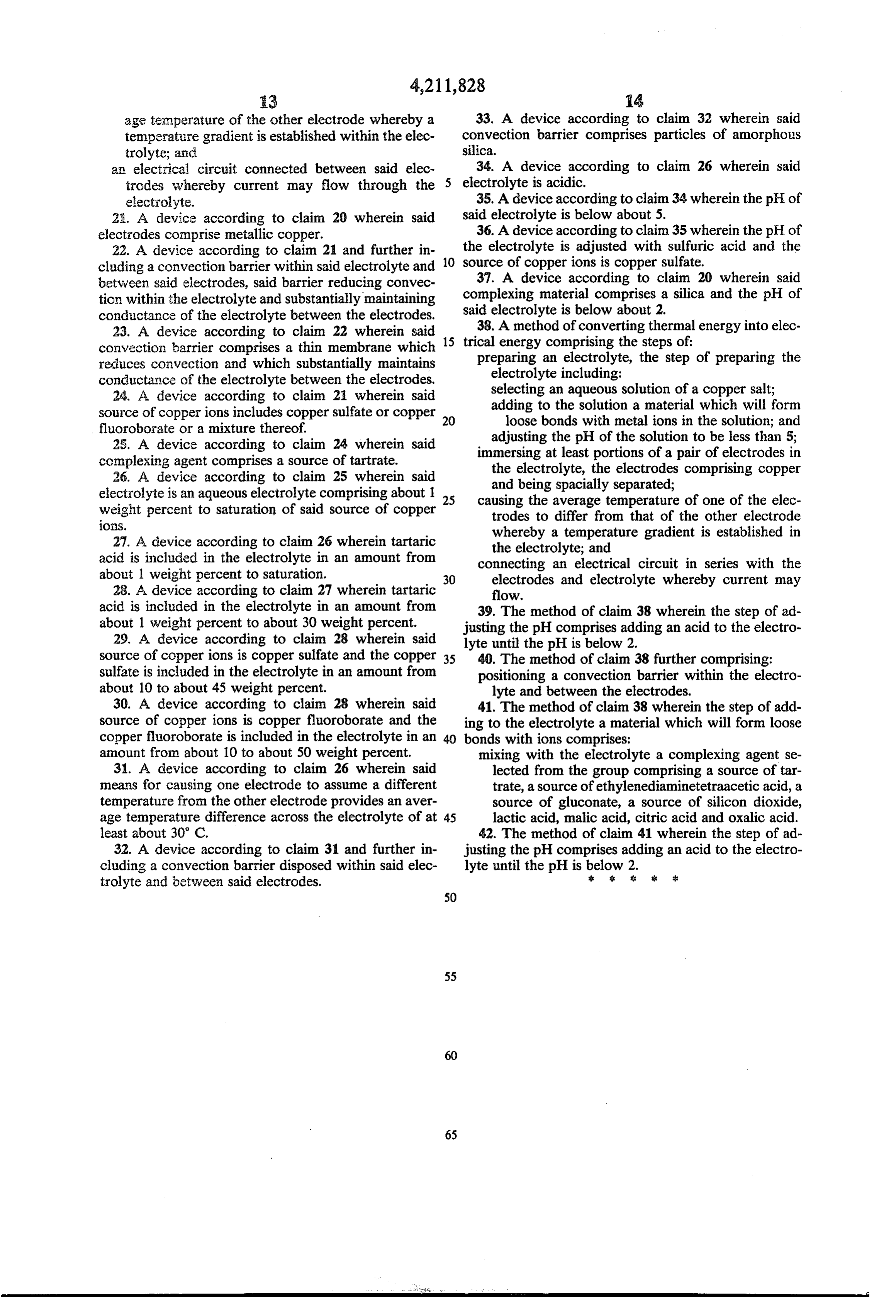
I claim: 16. A system according to claim 3 wherein the pH of 1. A thermoelectric energy system comprising: the electrolyte is adjusted with sulfuric acid and the source of copper ions is copper sulfate.
(a) at least first and second separated electrodes, said 17. A system according to claim 2 wherein said elec electrodes including copper; 50 trolyte is acidic.
(b) a liquid electrolyte comprising a source of copper 18. A system according to claim 2 wherein the pH of ions and a material for complexing the ions, the said electrolyte is below about 5.
complexing material being selected from the group 19. A system according to claim 1 wherein the com consisting of one or a combination of a source of plexing material comprises a silica. tartrate, a source of ethylenediaminetetraacetic 55 20. An electrical device comprising: acid, a source of gluconate, lactic acid, malic acid, (a) at least two separated electrodes comprising cop citric acid, oxalic acid, and a source of silicon diox per;
ide, the electrolyte being disposed between and in (b) a liquid electrolyte including a source of copper contact with the electrodes to provide a metal ion ions and a complexing agent for said copper ions, conduction path which extends substantially the said electrolyte disposed between and in contact entire distance between the electrodes; with said electrodes, said complexing agent com (c) an electric circuit connected to the electrodes for prising a material which will form loose bonds with removal of electrical energy from the system; and copper ions and being selected from the group (d) means for establishing a temperature gradient comprising a source of tartrate, a source of ethyl within said electrolyte whereby the average tem 65 enediaminetetraacetic acid, a source of gluconate, a perature of one of said electrodes will be greater source of silicon dioxide or a combination thereof; than that of the other of said electrodes to thereby means for causing one of the electrodes to have an produce a voltage across the electrodes. average temperature which differs from the aver
Page 11
age temperature of the other electrode whereby a 33. A device according to claim 32 wherein said temperature gradient is established within the elec convection barrier comprises particles of amorphous trolyte; and silica.
an electrical circuit connected between said elec 34. A device according to claim 26 wherein said trodes whereby current may flow through the electrolyte is acidic.
electrolyte. 35. A device according to claim 34 wherein the pH of 2A. A device according to claim 20 wherein said said electrolyte is below about 5.
electrodes comprise metallic copper. 36. A device according to claim 35 wherein the pH of 22. A device according to claim 21 and further in the electrolyte is adjusted with sulfuric acid and the cluding a convection barrier within said electrolyte and 10 source of copper ions is copper sulfate. between said electrodes, said barrier reducing convec 37. A device according to claim 20 wherein said tion within the electrolyte and substantially maintaining complexing material comprises a silica and the pH of conductance of the electrolyte between the electrodes. said electrolyte is below about 2. 23. A device according to claim 22 wherein said 15 trical 38. A method of converting thermal energy into elec convection barrier comprises a thin membrane which energy comprising the steps of: reduces convection and which substantially maintains preparing an electrolyte, the step of preparing the conductance of the electrolyte between the electrodes. electrolyte including: 24. A device according to claim 21 wherein said selecting an aqueous solution of a copper salt; source of copper ions includes copper sulfate or copper 20 adding to the solution a material which will form fluoroborate or a mixture thereof. loose bonds with metal ions in the solution; and 25. A device according to claim 24 wherein said adjusting the pH of the solution to be less than 5; complexing agent comprises a source of tartrate. immersing at least portions of a pair of electrodes in 26. A device according to claim 25 wherein said the electrolyte, the electrodes comprising copper and being spacially separated;
electrolyte is an aqueous electrolyte comprising about 1 25 causing the average temperature weight percent to saturation of said source of copper of one of the elec trodes to differ from that of the other electrode
whereby a temperature gradient is established in 27. A device according to claim 26 wherein tartaric the electrolyte; and acid is included in the electrolyte in an amount from connecting an electrical circuit in series with the about 1 weight percent to saturation. 30 electrodes and electrolyte whereby current may 28. A device according to claim 27 wherein tartaric flow.
acid is included in the electrolyte in an amount from 39. The method of claim 38 wherein the step of ad about 1 weight percent to about 30 weight percent. justing the pH comprises adding an acid to the electro 29. A device according to claim 28 wherein said lyte until the pH is below 2.
source of copper ions is copper sulfate and the copper 35 40. The method of claim 38 further comprising: sulfate is included in the electrolyte in an amount from positioning a convection barrier within the electro about 10 to about 45 weight percent. lyte and between the electrodes. 30. A device according to claim 28 wherein said 41. The method of claim 38 wherein the step of add source of copper ions is copper fluoroborate and the ing to the electrolyte a material which will form loose copper fluoroborate is included in the electrolyte in an 40 bonds with ions comprises:
amount from about 10 to about 50 weight percent. mixing with the electrolyte a complexing agent se 31. A device according to claim 26 wherein said lected from the group comprising a source of tar means for causing one electrode to assume a different trate, a source of ethylenediaminetetraacetic acid, a temperature from the other electrode provides an aver source of gluconate, a source of silicon dioxide, age temperature difference across the electrolyte of at 45 lactic acid, malic acid, citric acid and oxalic acid. least about 30' C. 42. The method of claim 41 wherein the step of ad 32. A device according to claim 31 and further in justing the pH comprises adding an acid to the electro cluding a convection barrier disposed within said elec lyte until the pH is below 2.
trolyte and between said electrodes.
Provenance
- Collection
- Cited prior art
- Original PDF
- patentimages.storage.googleapis.com →
- Filed
- 1978-11-09
- Pages
- 11
- Method
- pdftotext (the PDF's own text layer) + pdftoppm 300dpi page scans
- Source
- Google Patents bibliographic record
- Granted
- 1980-07-08
- Inventors
- Robert L. Peck; Atlantic Richfield Co
- Transcribed from
- patentimages.storage.googleapis.com →