patent · US5316870
Heat supply and electric power-generating fuel cell
31 May 1994
Page 1 — bibliographic record
United States Patent (19) 11 Patent Number: 5,316,870 Ohga (45) Date of Patent: May 31, 1994 (54. HEAT SUPPLY AND ELECTRIC 57 ABSTRACT
POWERGENERATING FUEL CELL
A heat supply and electric power-generating fuel cell, 75 Inventor: Shunsuke Ohga, Kawasaki, Japan has a water-circulation system including a fuel cell body 73) Assignee: Fuji Electric Co., Ltd., Kanagawa, with a water flow path for controlling the temperature Japan of a cell reaction to a proper temperature. A water vapor separator cools water passed through the water 21 Appl. No.: 887,828 flow path of the fuel cell. A recovery heat exchanger supplies heat to users which corresponds to the differ 22 Filed: May 26, 1992 ence between the temperature of the water cooled by 30 Foreign Application Priority Data the separator and the proper temperature of the cell reaction when the temperature of the water is greater
May 27, 1991 JP Japan .................................. 3-120521 than the proper temperature. A control heat exchanger, 51) int. Cli.............................................. HO1M. 8/04 on a water path connecting the separator with the re 52 U.S.C. ......................................... 429/24; 429/26 covery heat exchanger, includes a heat exchange por 58) Field of Search ....................... 429/24, 26; 165/58 tion having a path for a heat transfer medium, and cool ing structure for cooling the water with air. A circulat (56) References Cited ing pump circulates water around a water-circulation
heat from the heating/cooling structure to adjust the 2,720,936 10/1955 Beu ................................... 165/58 X temperature of water heat-exchanged with the heat 3,539,397 11/1970 Keating et al. ... 429/24X exchange portion when the temperature of the cell 3,653,431 4/1972 Loveley ........ ... 165/58 X reaction is reduced, and controls the quantity of air 3,952,794 4/1976 Spanoudis..... ... 165/58 X supplied from the heating/cooling structure toward the 4,824,740 4/1989 Abrams et al. ... ... 429/24 5,023,151 6/1991 Landau et al. ........................ 429/24 heat exchange portion when the temperature of the cell reaction is increased.
Primary Examiner-Stephen Kalafut
Attorney, Agent, or Firm-Spencer, Frank & Schneider 6 Claims, 4 Drawing Sheets
Page 2
Drawing sheet — no readable text.
Page 3
Drawing sheet — no readable text.
Page 4
Drawing sheet — no readable text.
Page 5
Drawing sheet — no readable text.
Page 6
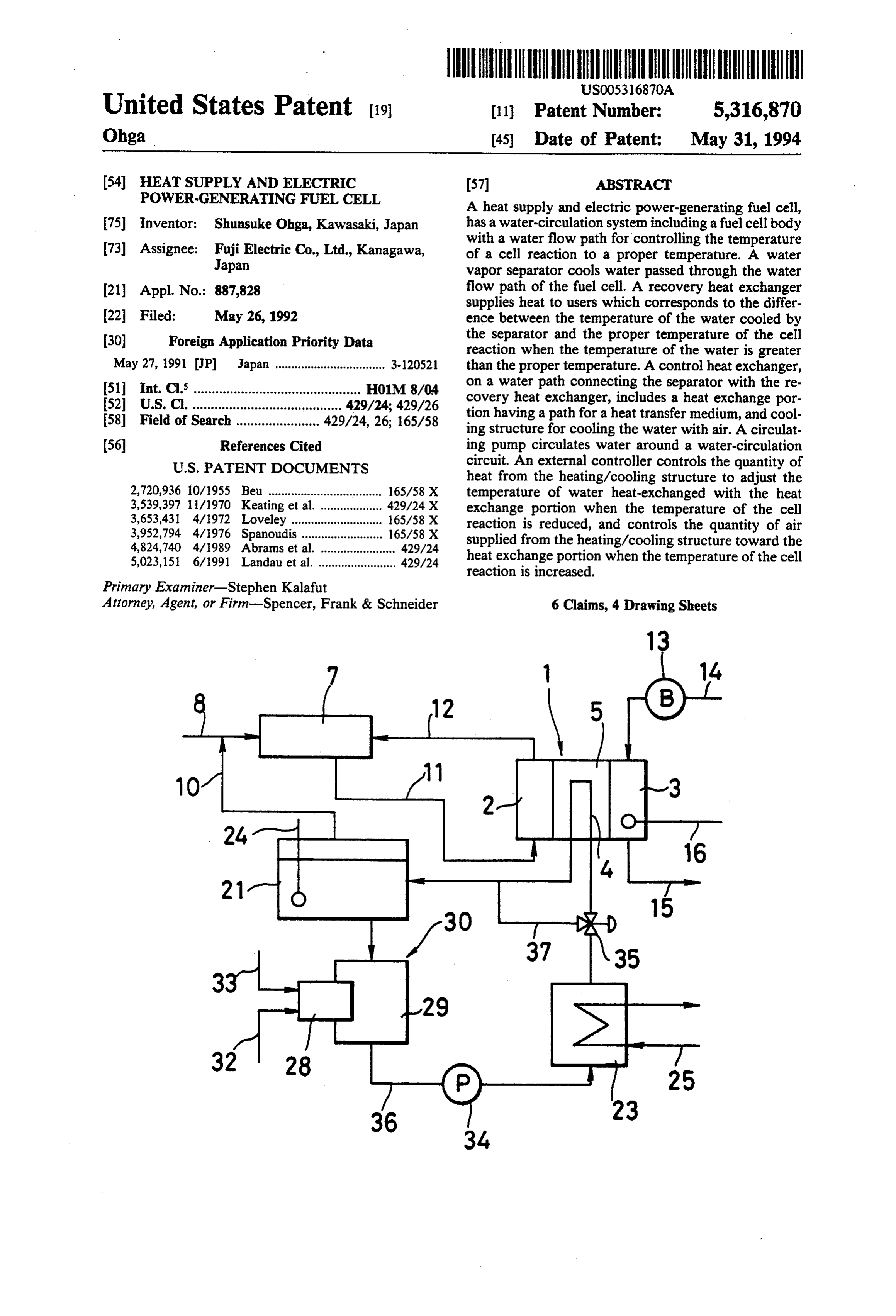
separator 21, a pump 22 for circulating the cooling
HEAT SUPPLY AND ELECTRIC water and a heat exchanger 23 for recovering heat. POWER-GENERATING FUEL CELL The water vapor separator 21 serves to separate water vapor from the water discharged from the cool
BACKGROUND OF THE INVENTION 5 ing pipes 4 of the fuel cell body 1. The water vapor 1. Field of the Invention separated is transferred to the fuel-reforming apparatus The present invention relates to a heat supply and 7 through the water vapor supply system 10 in which it electric power-generating fuel cell in which a body of a is admixedawith a starting fuel. Reference numeral 24 fuel cell incorporated into a fuel cell power generator is 10 represents thermometer for detecting the temperature heated with hot water during starting to preheat the cell . of the water in the water vapor separator 21. body and cooled by cooling water during power-gener The heat exchanger 23 for recovering heat serves to ation to remove a part of the heat of reaction, whereby perature.the recover heat of the water having an elevated tem
In the heat exchanger 23, the temperature of a the temperature of the cell body is maintained at a con heat transfer medium to be supplied to users is raised stant level while supplying heat to users. 15 through the heat-exchange with the heated cooling 2. Description of the Prior Art
There has been known a fuel cell to be incorporated waterthrough and the heat transfer medium is supplied to the into a fuel cell power generator whose fuel cell body is users a heat transfer medium supply system 25. In addition to the water-circulation system 20, the cooled with cooling water to remove a part of the heat water generated during the power-generation and to thus 20 systemvapor separator 21 further has a water-circulation maintain the fuel cell body at a predetermined operating supply 31 for starting the fuel cell body, which serves to the water separated in the water vapor separator temperature and which can thus supply heat to users through the heat exchange between the cooling water 21 to a circulating pump 27 for starting through a heat exchanger 30 for heating which comprises a heat ex thus heated and a properheat transfer medium. The fuel change part 29 having a heating burner 28 and to then cell is further equipped with a means for heating, with 25 return the water to the water vapor separator 21. hot water, the fuel cell body up to a temperature suit able for the cell reaction during starting of the fuel cell. thereto throughexchanger
In the heat a fuel 30 for heating, the fuel fed supply system 32 is combusted by
FIG. 1 is a system diagram showing a fuel cell power the heating burner 28 while supplying a combustion air generator provided with such a conventional fuel cell. fed thereto through a combustion air supply In FIG. 1, a fuel cell body1 is schematically depicted 30 and the temperature of the water fed to thesystem heat
and has a plurality of units cells, which are put on top of changer is raised through the heat exchange between each other and each comprises a fuel electrode 2, an the heat transfer medium generated during the combus oxide electrode 3 and a phosphoric acid electrolyte tion and the water.
layer (not shown) sandwiched between these elec Upon starting a fuel cell having such a structure, the trodes, and a cooling plate 5 having with cooling pipes 35 circulating pump 27 for starting the cell of the system 31 4 which are provided for every unit cells and serve as for circulating the starting water is started and simulta water flow paths.
In a fuel-reforming apparatus 7, a starting gas such as neously the combustion of the fuel is started by igniting the heating burner 28, whereby the water in the water a natural gas supplied thereto through a fuel supply vapor separator 21 is circulated along the system 31 for system 8 is heated by water vapor supplied from a water circulating the starting water and simultaneously heated vapor separator 21, as will be detailed below, through a to 170° C. by the action of the heat generated during water vapor supply system 10 as well as the heat gener combustion of the fuel in the heating burner 28 to give ated during combustion of an off-gas in a burner (not water vapor.
shown) in the presence of a reforming catalyst, as will The pump 22 for circulating cooling water during be detailed below, to give a reformed gas rich in hydro 45 operation of the system 20 is operated to circulate the gen. heated water in the water vapor separator 21 through The fuel cell body 1 and the fuel reforming apparatus the system 20 for circulating water for operation and 7 are communicated to one another through a reformed the cooling pipes 4 within the cooling plate 5 of the fuel gas supply system 11 and an off-gas supply system 12 to cell body 1 to thus heat fuel cell body 1 and raise the form a circulation system for the reformed gas, the 50 temperature of the cell body up to a level suitable for reformed gas supply system serving as a means for sup progressing the cell reaction. After completion of the plying the reformed gas generated in the fuel-reforming desired temperature rise, the circulating pump 27 for apparatus 7 to the fuel electrode 2 of the fuel cell body starting the cell and the heating burner 28 are stopped. 1 and the off-gas supply system serving as a means for At the time when the temperature of fuel cell body 1 supplying an off-gas including hydrogen gas, which is 55 reaches a desired level, the reformed gas generated in discharged from the fuel electrode 2 and does not take the fuel-reforming apparatus 7 is fed to the fuel elec part in the cell reaction, to the burner of fuel-reforming trode 2 through reformed gas supply system 11, while apparatus as a fuel. air is supplied to the oxide electrode 3 by the blower 13 Moreover, the fuel cell body I is connected to an air through the air supply system 14 and thus the fuel cell supply system 14 having a blower 13 for supplying air body 1 causes the cell reaction to produce electric to the oxide electrode 3 and an air exhaust system 15 for power. The heat generated during the cell reaction is evacuating the air used in the cell reaction. Reference removed by the water circulating through the water numeral 16 represents a thermometer for detecting the circulation system 20 for operation and correspondingly temperature of the fuel cell body 1. the temperature of the fuel cell is maintained at a prede To circulate cooling water through the fuel cell body 65 termined level.
1 during power-generation, the cooling pipes 4 fitted to The off-gas generated during the cell reaction is fed the cooling plate 5 of the fuel cell body 1 are connected to the burner of the fuel-reforming apparatus 7 through to a water-circulation system 20 which has water vapor the off-gas supply system 12 while exhaust air used in
Page 7
the cell reaction is released in the air through the air charged from the water vapor separator through heat exhaust system 15. exchange between water discharged from the water Incidentally, the water whose temperature is raised vapor separator and a heated first heat transfer medium; through the cooling of fuel cell body 1 transfers heat to a second heat exchanger for recovering heat from water a heat transfer medium such as water through heat heated by the first heat exchanger through heat ex exchange within the heat exchanger 23 for recovering change between water heated by the first heat ex heat and the heat transfer medium thus heated to an changer and a second heat transfer medium for supply elevated temperature is supplied to users in the form of ing heat to users; and a circulating pump for returning Steam. water, which is cooled through heat exchange per When a fuel cell having the foregoing structure pro O formed in the second heat exchanger, to the water duces electric power and simultaneously provides heat vapor separator.
by making use of the heat of reaction during the power The first heat exchanger may have a heat exchang generation, a desired quantity of heat must always be part for performing heat exchange and a heating burner supplied to the fuel cell to produce a predetermined for heating a heat transfer medium which is present in quantity of electric energy. For this reason, for instance, 15 the heat exchange part. The heat exchange part of the the temperature and pressure of the steam as a heat first heat exchanger may be a part for exchanging heat transfer medium to be supplied to users are controlled between water discharged from the water vapor separa to predetermined ranges respectively. In such a heat tor and the heat transfer medium heated by the heating supply and powergenerating system, however, a de burner of the first heat exchanger.
mand for heat is not always proportional to that for The heat exchange part of the first heat exchanger generated energy. For instance, if the demand for heat may also be a part for exchanging heat between water is lower than that for electric power, users must deal discharged from the water vapor separator and the with the excess or residual heat. On the other hand, combustion air discharged from the heating burner of even if the demand for heat is greater than that for the the first heat exchanger.
electric power, the temperature and pressure of the 25 A selector valve may be arranged in the path between steam to be supplied to users are controlled to predeter the second heat exchanger and the flow path of the fuel mined ranges for preventing any reduction in the oper cell body of the water circulation system, the selector ating temperature of the fuel cell. This leads to a limita valve selecting either or both of the paths which serve tion in the quantity of heat to be supplied. to return water discharged from the second heat ex If the temperature and pressure of the steam are not 30 changer to the water vapor separator through the flow controlled to predetermined ranges and the operating path.
temperature of the fuel cell is dropped because of an In a second aspect of the present invention, the heat increase in heat used by users over the heat of reaction supply and electric power-generating fuel cell comprise generated during the power-generation, the desired a water-circulation system which includes a fuel cell temperature of fuel cell body 1 may be maintained by 35 body having a water flow path for controlling the tem heating the water in the water vapor separator 21 perature of a cell reaction to a proper level; a water through the operation of the pump 27 for circulating the vapor separator for separating water vapor from water starting water and heating burner 28. In this case, how discharged from the water flow path of the fuel cell ever, this operation results in a delay of the response of body; a heat transfer medium-heat exchanger having a the fuel cell for a time required for raising temperature 40 heat transfer medium the heat transfer medium-heat to a desired level due to the high heat capacity of the exchanger for exchanging heat between water dis water. More specifically, it takes a long time period charged from the water vapor separator and the heat from the detection of the temperature drop in the fuel transfer medium; an air-heat exchanger for exchanging cell till the operation temperature thereof reaches the heat between water discharged from the water vapor predetermined level by operating the heating burner. 45 separator and air, the air-heat exchanger and the heat In general, the fuel cell power generator requires a transfer medium-heat exchanger disposed in series; a large area for establishment per unit output as compared recovering heat exchanger for recovering heat from with other kinds of power generators. Accordingly, water heated by a series of the heat exchangers through there has been a demand for making the generator more heat exchange between water heated by a series of the compact through elimination of unnecessary parts and 50 heat exchangers and a second heat transfer medium for /or integration of two or more of parts. supplying heat to users; and a circulating pump for SUMMARY OF THE INVENTION returning water, which is cooled through heat exchange performed in the recovering heat exchanger, to the
It is an object of the present invention to provide a water vapor separator.
heat supply and electric power-generating fuel cell 55 A selector valve may be arranged in the path between which has a wide allowance in the unbalance between the recovering heat exchanger and the flow path of the the demand for power-generation and that for the heat fuel cell body of the water circulation system, the selec or can widely vary both demand for generated energy tor valve selecting either or both of the paths which and heat during operation of the fuel cell and supply of serve to return water discharged from the recovering heat to users and which is very compact. 60 heat exchanger to the water vapor separator through In a first aspect of the present invention, the heat the flow path.
supply and electric power-generating fuel cell comprise In a third aspect of the present invention, the heat a water-circulation system which includes a fuel cell supply and electric power-generating fuel cell comprise body having a water flow path for controlling the tem a water-circulation system which includes a fuel cell perature of a cell reaction to a proper level; a water 65 body having a water flow path for controlling the tem vapor separator for separating water vapor from water perature of a cell reaction to a proper level; a water discharged from the water flow path of the fuel cell vapor separator for separating water vapor from water body; a first heat exchanger for heating water dis discharged from the water flow path of the fuel cell
Page 8
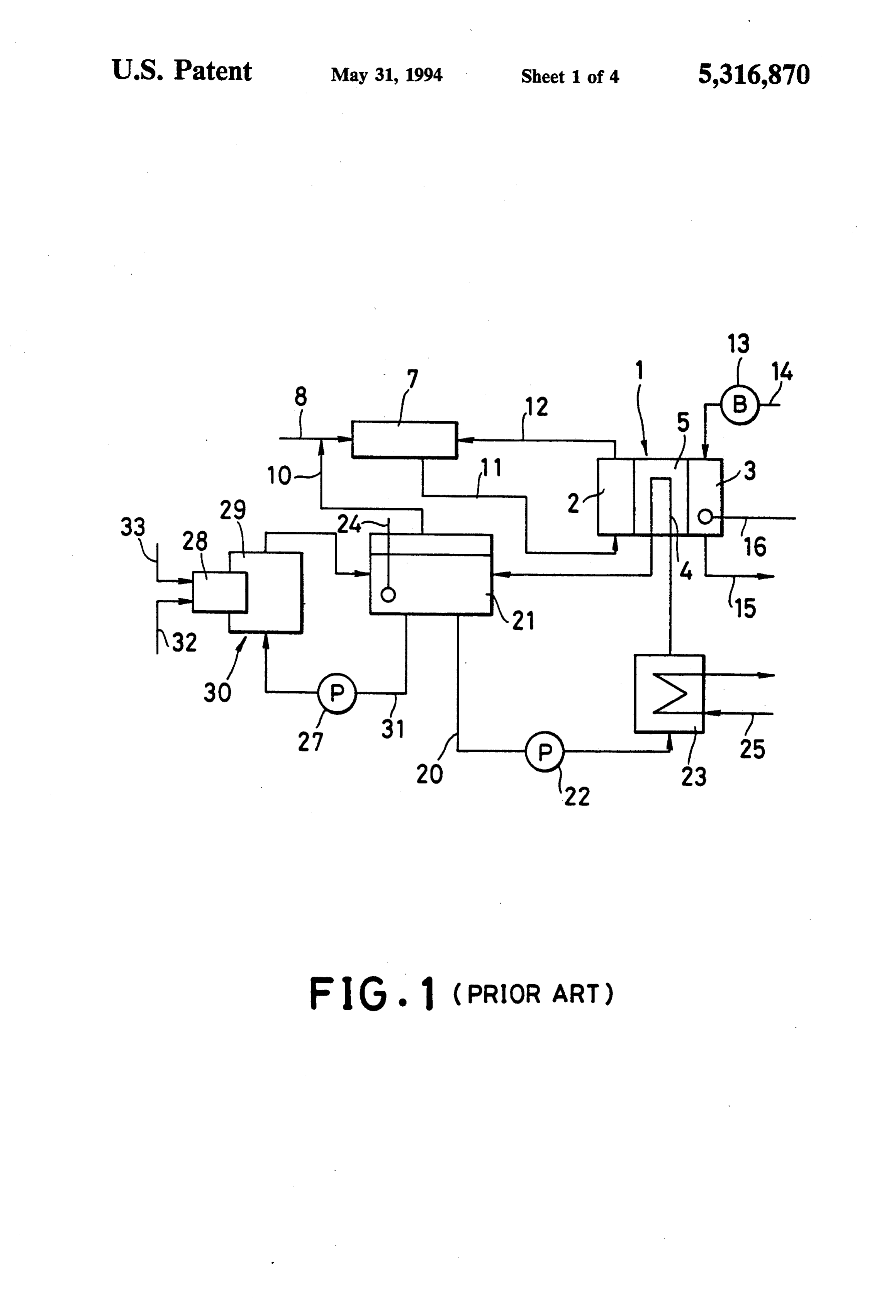
body; an integrated heat exchanger for simultaneously tion system 20 for staring the fuel cell as shown in FIG. performing heating and heat-recovery among water 1. A water circulation system 36 is provided with a discharged from the water vapor separator, a heated bypass system 37 for returning the circulating water to first heat transfer medium and a second heat transfer the water vapor separator 21 through a three-way selec medium to be supplied to users; and a circulating pump tor valve 35.
for returning water, which is cooled through heat ex In the fuel cell having the foregoing construction, the change performed in the integrated heat exchanger, to circulating water flows in the direction of the water the water vapor separator. vapor separator 21 through the by-pass system 37 by A selector valve may be arranged in the path between switching the three-way selector valve 35 during start the integrated heat exchanger and the flow path of the 10 ing the fuel cell. Under such a condition, the circulating fuel cell body of the water circulation system, the selec water in heat exchanger 30 is heated, during starting the tor valve selecting either or both of the paths which fuel cell, by igniting the heating burner 28 of the heat serve to return water discharged from the integrated exchanger 30 to a temperature of 170° C. to give water heat exchanger to the water vapor separator through vapor as has already been discussed above. the flow path. 15 The three-way selector valve 35 is switched to flow The above and other objects, effects, features and the heated circulating water into the cooling pipe 4 of advantages of the present invention will become more the cooling plate 5. Thus, fuel cell body 1 is heated by apparent from the following description of embodi the heated circulating water up to a temperature suit ments thereof taken in conjunction with the accompa able for the cell reaction. When fuel cell body 1 is nying drawings. 20 heated, the circulating water released from the water BRIEF DESCRIPTION OF THE DRAWINGS vapor separator 21 of water circulating system 36 is heated through the heat exchange with a heat transfer
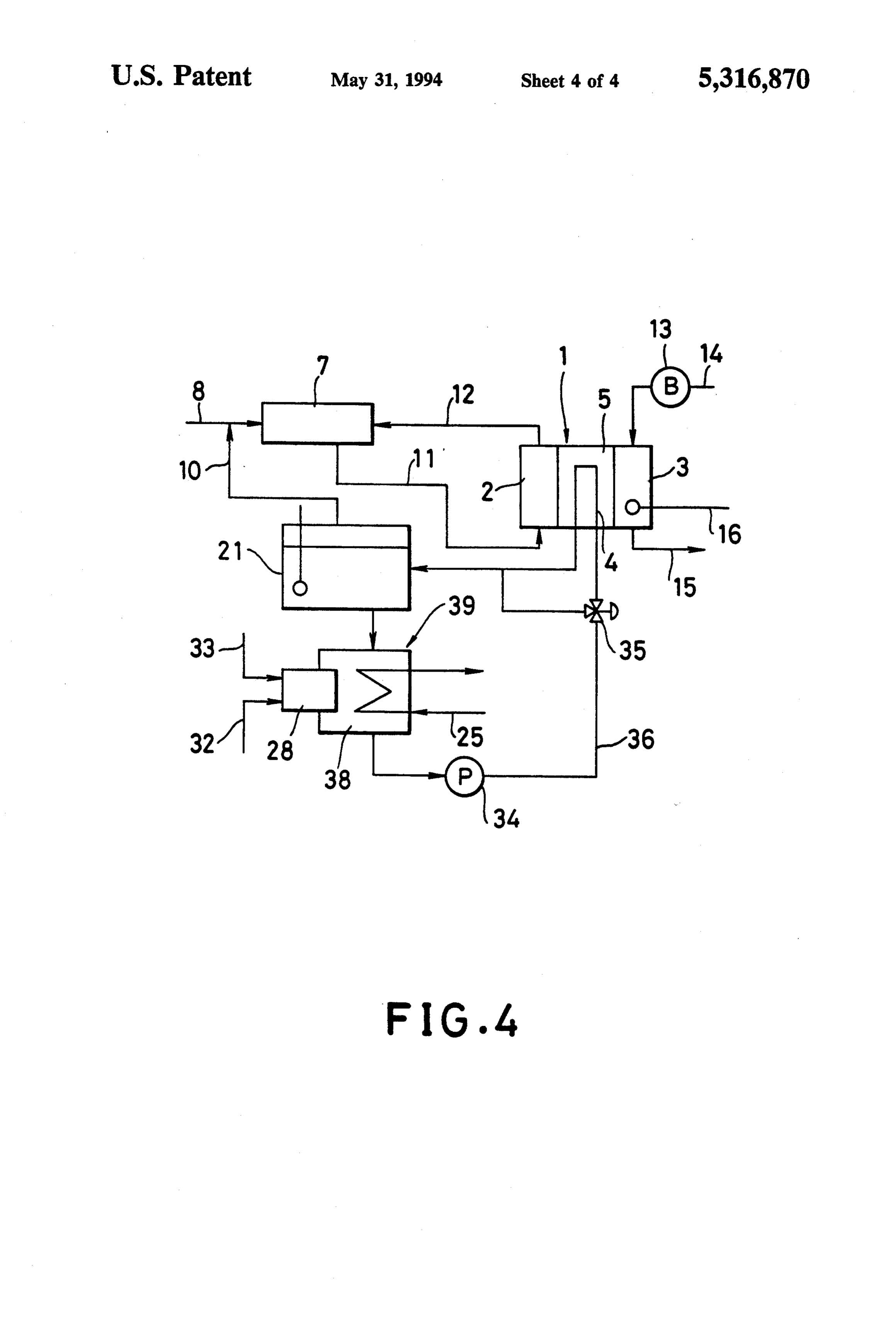
FIG. 1 is a block diagram showing a fuel cell power medium generated by the combustion of the heating generator provided with a conventional heat supply and burner 28 of the heat exchanger 30 and the whole power-generating fuel cell; 25 heated circulating water is returned to the water vapor FIG. 2 is a block diagram showing a fuel cell power separator 21 by switching the three-way selector valve generator provided with an embodiment of the heat 35. In such a manner, the circulating water is continu supply and power-generating fuel cell according to the ously heated and circulated until the temperature present invention; thereof reaches a predetermined level suitable for the FIG. 3 is a partial block diagram showing a heat 30 cell reaction in fuel cell body 1.
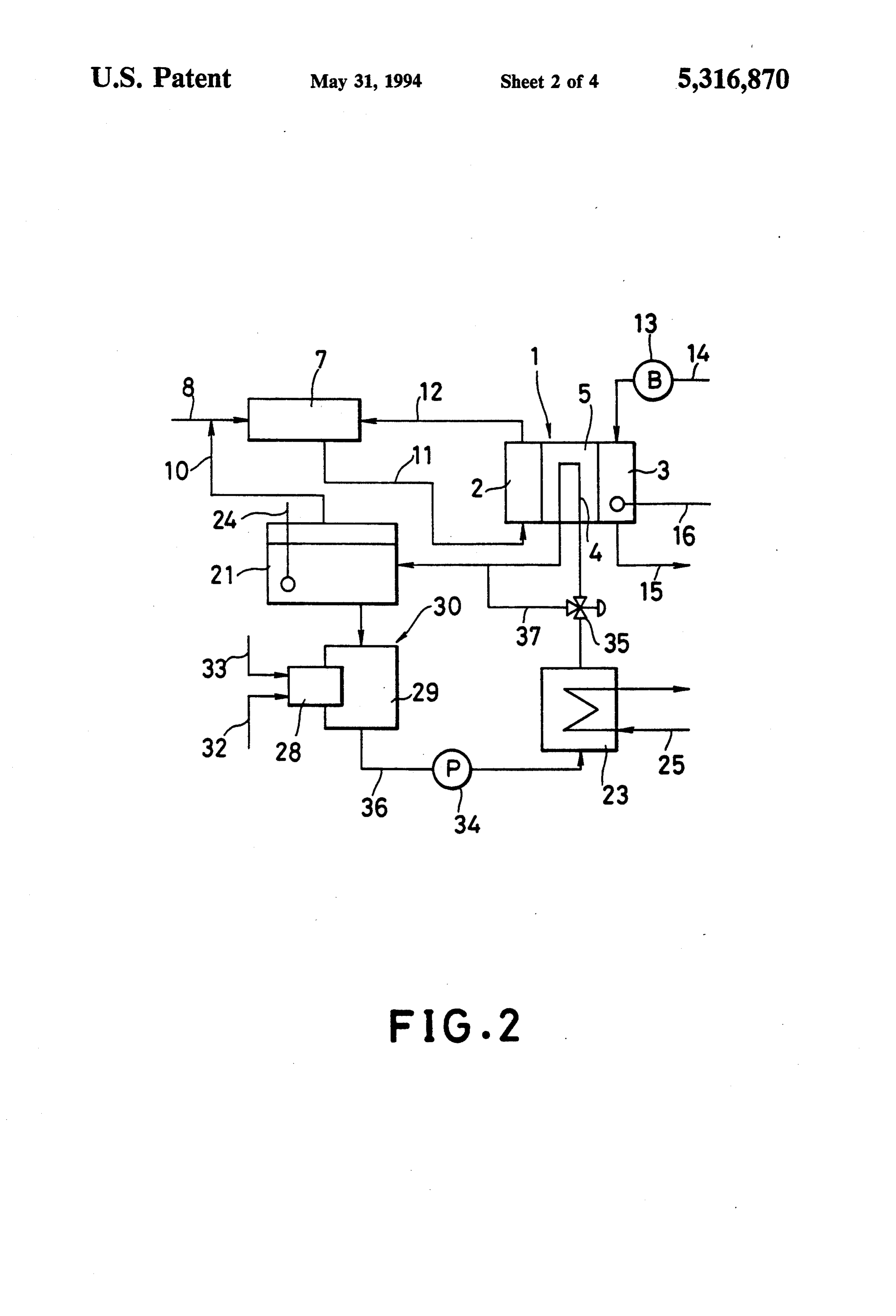
transfer medium-heat exchanger and an air-heat ex After the completion of the heating of the water, the changer capable of being incorporated in the heat sup three-way selector valve 35 is switched so that the ply and power-generating fuel cell as shown in FIG. 2; whole water is supplied to the cooling plate 5 to thus FIG. 4 is a block diagram showing a fuel cell power elevate the temperature of fuel cell body 1 to a level generator provided with another embodiment of the 35 favorable for the cell reaction. After the completion of heat supply and power-generating fuel cell according to the temperature rise, the combustion of the heating the present invention; and burner 28 is stopped.
FIG. 5 is an enlarged block diagram illustrating an In this respect, the flow rate of the circulating water integrated heat exchanger to be incorporated into the in the cooling pipe 4 of fuel cell body 1 can be con heat supply and power-generating fuel cell as shown in trolled by gradually varying the opening angle of the FIG. 4. three-way selector valve 35 so that the thermal shock DETAILED DESCRIPTION OF THE exerted on fuel cell body 1 would be relieved. PREFERRED EMBODIMENTS As has been discussed above, the cell reaction is initi ated by supplying a reformed gas and air to the fuel cell
Embodiments of the present invention will hereinaf 45 body 1 after the temperature of the fuel cell body 1 is ter be described in more detail with reference to the raised to a predetermined level to produce electric accompanying drawings. FIG. 1 is a system diagram power. The circulating water is cooled through the heat showing a fuel cell power generator provided with an exchange with a heat transfer medium to be supplied to embodiment of the heat supply and power-generating users in the heat exchanger 23 for heat-recovery by fuel cell according to the present invention. For the 50 flowing it into the water circulation system 36 during sake of simplicity, the same parts appearing on FIG. 2 the power-generation and the cooled circulating water and FIGS. 3 to 5 as will be explained below as those is supplied to the fuel cell body 1 to remove heat gener appearing on FIG. 1 are denoted by the reference nu ated during the production of electric power and to, in merals used in FIG. 1 and explanation thereof is omit turn, hold the desired operating temperature of the fuel ted. 55 cell boy 1 as described above.
The fuel cell of the present invention shown in FIG. The operating temperature of the fuel cell during 2 differs from the conventional one shown in FIG. 1 in power generation is greatly affected by the temperature that the former is provided with a water circulation and flow rate of the heat transfer medium supplied, on system 36 having a heat exchanger 30 for heating as a the user side, to heat exchanger 23 for recovering the first heat exchanger which has the water vapor separa that of reaction generated accompanied by the power tor 21 and the heat exchanger 29 provided with the generation. Therefore, the operating temperature of the heating burner 28; a circulating pump 34 for feeding the fuel cell is controlled by the circulating water through circulating water discharged from that exchanger 30 the heat exchange in the heat exchanger 30 of the water under pressure, the heat exchanger 23 for recovering circulation system 36 while monitoring the operating that as a second heat exchanger, a three-way selector 65 temperature of the fuel cell, whereby excess heat can be valve 35 for returning the circulating water discharged discharged or deficiency of heat can be compensated so from the heat exchanger 23 to the cooling plate 5 or the as to lighten the burden of the user. The problems of the water vapor separator 21, instead of the water circula excess heat and the deficiency of heat arise due to the
Page 9
unbalance between the demand for the generated en separator 21, the heat exchanger 30 for heating or the ergy and that of the heat extracted through the heat heat transfer mediumand air-heat exchanger 54 and the exchange in the heat exchanger for heat recovery. heat exchanger 53 for removing heat by the action of In other words, if the quantity of heat extracted from the circulating pump 34 during operation of the fuel cell the heat exchanger for heat recovery is greater than the body and which allows for the circulating water to heat generated through the cell reaction accompanied bypass the cooling plate 5 and accordingly, the temper by the power-generation in the fuel cell and the operat ature rise of the fuel cell body 1 during starting as well ing temperature of the fuel cell is correspondingly re as the temperature rise and drop of fuel cell body 1 duced, the reduction of the temperature of the circulat during power-generation are performed without using a ing water is detected by the thermometer 16 of the fuel O cooling water circulation system for starting as in the cell body 1. The circulating water is heated in the heat conventional fuel cell. Consequently, the temperature exchanger 30 by igniting the heating burner 28 which is rise and drop of the circulating water can be achieved controlled by a controller (not shown) on the basis of without accompanying any delay of the response of the data from the thermometer 16 to adjust the quantity of fuel cell for a time required for raising temperature to a heat obtained by the heating burner 28. The fuel cell 15 desired level due to the high heat capacity of the water. body 1 is heated through the circulation the heated In particular, the fuel cell can quickly respond to a circulating water to thus hold the desired operating possible unbalance between the demand for the gener temperature thereof. ated energy during production of electric power and On the other hand, if the quantity of heat extracted that for the heat consumption and can thus recover the from the heat exchanger for heat recovery is smaller 20 desired operating temperature of the fuel cell. In other than the heat generated through the cell reaction ac words, the cell can deal with a great unbalance between companied by the power-generation in the fuel cell and the demand for the generated energy and that for the the operating temperature of the fuel cell is correspond heat consumption.
ingly increased, the increase of the temperature of the FIG. 4 is a system diagram showing a fuel cell power circulating water is detected by the thermometer 16 of 25 generator provided with another embodiment of the the fuel cell body 1. The circulating water is cooled by heat supply and power-generating fuel cell according to supplying only the combustion air to the heating burner the present invention. The apparatus shown in FIG. 4 is 28 without igniting the same and the fuel cell body 1 is identical to that shown in FIG. 2 except that it has an cooled through the circulation of the cooled circulating integrated heat exchanger 39 having a heating burner 28 water to thus hold the desired operating temperature 30 and a heat exchanger 38 and which simultaneously has thereof. functions of both that exchanger 23 and heat exchanger Since it is not necessary, in the apparatus having the 30 having heat exchanger 29 provided with the heating foregoing structure, to heat the circulating water by the burner 28 (see FIG. 2), the integrated heat exchanger water circulation system through the water vapor sepa being incorporated into the water circulation system 36 rator 21 as in the conventional apparatus, the apparatus 35 between the water vapor separator 21 and circulating of the present invention can eliminate the problem of a pump 34.
delay of the response of the fuel cell for a time required The integrated heat exchanger 39 is a plate type heat for raising temperature to a desired level due to the high exchanger as shown in FIG. 5. Alternatively, it may be heat capacity of the water and further the apparatus of a plate-fin type heat exchanger. As shown in FIG. 5, the the present invention can deal with the unbalanced 40 integrated heat exchanger 39 is provided with the heat relation between the demand for the generated energy ing burner 28 at one end of a casing 40, The casing 40 and that for the heat consumption or makes it possible has a flow path through which a combustion gas gener to widely vary the interrelation therebetween. ated by igniting the heating burner 28 passes, a flow In this case, the ability of the heating burner 28 and path 43 defined by separators 42 through which circu that of the heat exchanger 29 to transfer heat to the 45 lating water flows and a flow path 45 defined by separa circulating water by the combustion of the burner tors 44 through which a heat transfer medium supplied through the heat transfer medium must be determined by users passes, the flow paths being put in layers in advance by examining the ratio of the demand for through heat transfer plates. Such an integrated heat generated energy to that for heat in the apparatus as a exchanger 39 makes it possible to perform heat ex co-generation system. 50 change between the combustion gas, the cooling water Alternatively, it is also possible to arrange a heat and the heat transfer medium.
transfer medium-heat exchanger 53 which performs In FIG. 5, reference numeral 46 represents a combus that exchange between the circulating water and a heat tion chamber in which combustion is performed by the transfer medium such as a heat transfer oil and an air heating burner 28; reference numeral 47 represents a heat exchanger 54 in which heat is exchanged with air 55 manifold for combustion-exhaust gas discharged from in series with water circulation system 36 as shown in the combustion gas flow path; reference numeral 48 FIG. 3, instead of heat exchanger 30 for heating shown represents a circulating water inlet manifold; reference in FIG. 1 so that a high temperature heat transfer oil is numeral 49 represents an outlet manifold for the circu supplied to the heat transfer medium-heat exchanger 53 lating water discharged from the circulating water flow when it is needed to heat the circulating water, while path 43; reference numeral 50 represents an inlet mani low temperature air is fed to the air heat exchanger 54 fold through which the heat transfer medium supplied when it is intended to cool the circulating water, in by the user flows into the manifold and reference nu order to heat or cool the circulating water. meral 51 represents an outlet manifold for the heat This embodiment has the water circulating system 36 transfer medium discharged through the flow. path 45. which circulates the circulating water, which heats the 65 The function of the integrated heat exchanger having fuel cell body 1 during starting the fuel cell body and such a structure are as follows. As shown in FIG. 4, removes heat of reaction during operating the fuel cell combustion is performed in the combustion chamber 46 body, through the cooling plate 5, the water vapor while feeding a fuel 32 and combustion air 33 to the
Page 10
heating burner 28, the resulting combustion gas flows in Moreover, the fuel cell shows a quick response of heat the direction of the exhaust gas manifold 47 through the supply to users since the heat transfer medium under combustion gas flow path and released in the air goes heat exchange with the combustion gas discharged through the manifold 47. from a heating burner or combustion air passing On the other hand, the circulating water flows into through the heating burner.
the circulating water inlet manifold 48, and is trans The present invention has been described in detail ferred to the circulating water flow path 43 through the with respect to preferred embodiments, and it will now manifold and externally released through the circulat be apparent from the foregoing to those skilled in the art ing water outlet manifold 49. that changes and modifications may be made without The heat transfer medium supplied by the user flows 10 departing from the invention in its broader aspects, and into the heat medium inlet manifold 50 and is returned it is the intention, therefore, in the appended claims to to the user through heat medium flow path and the heat cover all such changes and modifications as fall within medium outlet manifold 51. the true spirit of the invention. As explained above, the combustion gas flow path, What is claimed is:
the circulating water flow path 43 and the heat transfer 15 1. A heat supply and electric power-generating fuel medium flow path 45 are arranged in layers through cell, comprising a water-circulation system including: heat transfer plates. This ensures the occurrence of the (1) a fuel cell body having a water flow path for heat exchange between the combustion gas passing controlling the temperature of a cell reaction to a through the combustion gas flow path, the circulating proper temperature;
water passing through the flow path 43 and the heat 20 (2) a thermometer for detecting the temperature of transfer medium passing through the flow path 45. the cell reaction;
When the fuel cell is started or the temperature of the (3) a water vapor separator for cooling water passed fuel cell body 1 is raised, the fuel cell body 1 is heated through said water flow path of said fuel cell body; by heating the circulating water through the heat ex (4) a recovery heat exchanger for constantly supply change between the circulating water passing through 25 ing heat to users, said heat corresponding to the the flow path 43 and the combustion gas generated from difference between the temperature of the water the heating burner 28 and passing through the combus cooled by said water vapor separator and the tion gas flow path. proper temperature of the cell reaction in said fuel On the other hand, when the fuel cell produces elec cell body when the temperature of the water tric power and heat is supplied to users, the function of 30 cooled by said water vapor separator is greater the integrated heat exchanger is as follows. If the de than the proper temperature of the cell reaction; mand for heat is greater than that for electric power, the (5) a control heat exchanger arranged on a water path heat exchanger deals with the unbalance between the connecting said water vapor separator with said demand for heat and that for electric power by perform recovery heat exchanger, said control heat ex ing the heat exchange between the combustion gas pass 35 changer including:
ing through the combustion gas flow path and dis (a) a heat exchange portion having a path for flow charged from the heating burner 28, the circulating ing a heat transfer medium arranged therein; and water passing through flow path 43 and the heat trans (b) cooling means for cooling said water passed fer medium passing through the flow path 45, while through said control heat exchanger by air; and maintaining the predetermined operating temperature (6) a circulating pump for circulating water around a of the fuel cell. In this case, the heat exchanger shows a water-circulation circuit including said fuel cell quick response of heat supply to the user since the heat body, said thermometer, said water vapor separa is transferred to the heat transfer medium through the tor, said recovery heat exchanger and said control heat exchange. heat exchanger;
On the other hand, if the demand for heat is lower 45 wherein an external controller controls the quantity of than that for electric power, the heat exchanger deals heat from said heating/cooling means on the basis of with the unbalance between the demand for heat and data from said thermometer to adjust the temperature of that for electric power by passing the combustion air water heat-exchanged with said heat exchange portion through the combustion gas flow path without igniting when the temperature of the cell reaction during oper the heating burner 28 and performing the heat exchange 50 ating said fuel cell body is reduced, and controls the between the combustion air, the circulating water pass quantity of air supplied from said heating/cooling ing through the flow path 43 and the heat transfer me means toward said path of said heat exchange portion dium passing through the flow path 45, while maintain on the basis of data from said thermometer to adjust the ing the predetermined operating temperature of the fuel temperature of water heat-exchanged with said heat cell. In this case, the heat exchanger shows a quick 55 exchange portion when the temperature of the cell response of heat supply to the user since the heat is reaction during operating said fuel cell body is in extracted from the heat transfer medium through the creased.
heat exchange. 2. A heat supply and electric power-generating fuel In this embodiment, the water circulation system is cell, comprising a water-circulation system including: provided with an integrated heat exchanger. Therefore, (1) a fuel cell body having a water flow path for the heat supply and power-generating fuel cell can be controlling the temperature of a cell reaction to a made compact, there is not observed any delay of re proper temperature;
sponse due to the high heat capacity of the water to be (2) a thermometer for detecting the temperature of heated in water vapor separator as in the foregoing the cell reaction;
embodiment, the fuel cell can effectively deal with the 65 (3) a water vapor separator for cooling water passed unbalance between the demand for heat and that for through said water flow path of said fuel cell body; electric power during operating the cell while maintain (4) a recovery heat exchanger for constantly supply ing the desired operating temperature of the fuel cell. ing heat to users, said heat corresponding to the
Page 11
difference between the temperature of the water (3) a water vapor separator for cooling water passed cooled by said water vapor separator and the through said water flow path of said fuel cell body; proper temperature of the cell reaction in said fuel (4) an integrated heat exchanger for simultaneously cell body when the temperature of the water performing heating and heat-recovery of water cooled by said water vapor separator is greater discharged from said water vapor separator, said than the proper temperature of the cell reaction; integrated heat exchanger including: (5) a control heat exchanger arranged on a water path a recovery heat exchanger having a heat transfer connecting said water vapor separator with said medium for constantly supplying heat to users, recovery heat exchanger, said control heat ex said heat corresponding to the difference be changer including: O tween the temperature of the water cooled by (a) a heat transfer medium-heat exchanger having a said water vapor separator and the proper tem heat transfer medium, said heat transfer medium perature of the cell reaction in said fuel cell body heat exchanger for heat exchanging between when the temperature of the water cooled by water discharged from said water vapor separa 15 said water vapor separator is greater than the tor and said heat transfer medium; proper temperature of the cell reaction; and (b) an air-heat exchanger for heat exchanging be a control heat exchanger including a heat exchange tween water heat-exchanged with said heat portion having a path for flowing a heat transfer transfer medium of said heat transfer medium medium arranged therein;
heat exchanger and air supplied to said air-heat wherein said heat transfer medium is passed exchanger, wherein said air-heat exchanger and 20 through said heat exchange portion of said control said heat transfer medium-heat exchanger are heat exchanger, and said heat transfer medium is disposed in series; and passed through said recovery heat exchanger; and (c) a heating/cooling means for heating said heat (5) a circulating pump for circulating water around a transfer medium of said heat transfer medium 25 water-circulation circuit including said fuel cell heat exchanger or for supplying air to said air body, said thermometer, said water vapor separa heat exchanger to cool water discharged from tor, said recovery heat exchanger and said control said heat transfer medium-heat exchanger; and heat exchanger;
(6) a circulating pump for circulating water around a wherein heat from an external controller controls the quantity of said integrated heat exchanger on the basis of water-circulation circuit including said fuel cell data from said thermometer to adjust the temperature of body, said thermometer, said water vapor separa 30 water tor, said recovery heat exchanger and said control when the temperature with
of the said heat exchange portion cell reaction during oper heat exchanger; ating said fuel cell body is reduced. wherein an external controller controls the quantity of 4. A fuel cell as claimed in claim 1, further comprising heat from said heating/cooling means on the basis of 35 a selector valve arranged in the flow path between said data from said thermometer to adjust the temperature of recovery heat exchanger and said fuel cell body of said water heat-exchanged with said heat transfer medium water circulation heat exchanger when the temperature of the cell reac flow between saidsystem, said selector valve bypassing recovery heat exchanger and said tion during operating said fuel cell body is reduced, and fuel cell body to said water vapor separator. controls the quantity of air supplied from said heating /cooling means to said air-heat exchanger on the basis a selector valve arranged in a flow further 5. A fuel cell as claimed in claim 2, comprising path between said of data from said thermometer to adjust the temperature recovery heat exchanger and said fuel cell body of said of water heat-exchanged with said air-heat exchanger water circulation system, said selector valve bypassing when the temperature of the cell reaction during oper flow between said recovery heat exchanger and said ating said fuel cell body is increased. 45 fuel cell body to said water vapor separator. 3. A heat supply and electric power-generating fuel 6. A fuel cell as claimed in claim3, further comprising cell, comprising a water-circulation system including: a selector valve arranged in a flow path between said (1) a fuel cell body having a water flow path for integrated heat exchanger and said fuel cell body of said controlling the temperature of a cell reaction to a water circulation system, said selector valve bypassing proper temperature; 50 flow between said recovery heat exchanger and said (2) a thermometer for detecting the temperature of fuel cell body to said water vapor separator. the cell reaction; sk
Provenance
- Collection
- Cited prior art
- Original PDF
- patentimages.storage.googleapis.com →
- Filed
- 1992-05-26
- Pages
- 11
- Method
- pdftotext (the PDF's own text layer) + pdftoppm 300dpi page scans
- Source
- Google Patents bibliographic record
- Granted
- 1994-05-31
- Inventors
- Shunsuke Ohga; Fuji Electric Co Ltd
- Transcribed from
- patentimages.storage.googleapis.com →