patent · US5200278
Integrated fuel cell power generation system
6 April 1993
Page 1 — bibliographic record
IIIHHHHHHHHHHIII USOO5200278A
United States Patent (19) 11 Patent Number: 5,200,278 Watkins et al. 45 Date of Patent: Apr. 6, 1993
54 NTEGRATED FUE
(99 SERIESL POWER FOREIGN PATENT DOCUMENTS
75) Inventors: David S. Watkins, Coquitlam; Primary Examiner-Anthony Skapars
Vancouver; Danny G. Epp, Ltd. Agent, or Firm-McAndrews, Held & Malloy,
Tsawwassen; Robert D. Merritt,
Brian N. Gorbell, both of Vancou- 57 ABSTRACT ver, all of Canada An integrated fuel cell power generation system com 73) Assignee: Ballard Power Systems, Inc., North prises a fuel cell stack having a humidification section Vancouver, Canada and an electrochemically active section. The humidifi cation section imparts water vapor to an inlet hydrogen (21) Appl. No.: 670,245 containing fuel stream and an inlet oxygen containing oxidant stream. The electrochemically active section comprises fuel cells for promoting the electrocatalytic (22) Filed: Mar. 15, 1991 conversion of the humidified fuel and oxidant streams to electric current and product water. The electrochemi 51) Int, C. .............................................. HOM 8/06 cally active section also includes a coolant water stream 52 U.S. C. ........................................ 429/24; 429/26; for absorbing heat generated in the active section. The o 429/34 system includes a heat exchanger for removing heat 58) Field of Search ....................... 429/24, 26, 34, 40, from the coolant water stream exiting the active sec 429/17, 19, 20, 13 tion, a water separator for removing water from the oxidant stream exiting the fuel cell stack, and a coolant (56) References Cited reservoir for receiving the removed water stream from
3,134,697 3/1964 Niedrach . coolant water stream is drawn from the coolant reser 3,297,484 1/1967 Niedrach . VOl.
4,988,583 1/1991 Watkins et al. . 20 Claims, 7 Drawing Sheets
Page 2
Drawing sheet — no readable text.
Page 3
Drawing sheet — no readable text.
Page 4
Drawing sheet — no readable text.
Page 5
Drawing sheet — no readable text.
Page 6
Drawing sheet — no readable text.
Page 7
Drawing sheet — no readable text.
Page 8
Drawing sheet — no readable text.
Page 9
plates act as current collectors, provide support for the
INTEGRATED FUEL CELL POWER GENERATION electrodes, provide access channels for the fuel and SYSTEM oxidant to the respective anode and cathode surfaces, and provide channels for the removal of water formed
FIELD OF THE INVENTION during operation of the cell.
The present invention relates to electrochemical fuel Two or more fuel cells can be connected together in cells. More particularly, the present invention relates to seriesof the or in parallel to increase the overall power output assembly. In such arrangements, the cells are a fuel cell based electric power generation system hav ing integrated fuel, oxidant and coolant circuits. typically connected in series, wherein one side of a 10 given plate serves as an anode plate for one cell and the
BACKGROUND OF THE INVENTION other side of the plate is the cathode plate for the adja Electrochemical fuel cells generate electrical energy cent cell. Such a series connected multiple fuel cell by converting chemical energy derived from a fuel arrangement is referred to as a fuel cell stack, and is directly into electrical energy by the oxidation of the 15 usually stack held together by tie rods and end plates. The typically includes feed manifolds or inlets for fuel in the cell. A typical fuel cell includes an anode, a cathode and an electrolyte. Fuel and oxidant are sup directing the fuel (substantially pure hydrogen, metha nol reformate or natural gas reformate) and the oxidant plied to the anode and cathode, respectively. At the (substantially anode, the fuel permeates the electrode material and the anode andpure oxygen or oxygen containing air) to cathode flow field channels. The stack reacts at the anode catalyst layer to form cations, which migrate through the electrolyte to the cathode. At the also usually includes a feed manifold or inlet for direct cathode, the oxygen containing gas supply reacts at the ing the coolant fluid, typically water, to interior chan cathode catalyst layer to form anions. The anions nels within the stack to absorb heat generated by the formed at the cathode react with the cations to form a exothermic reaction of hydrogen and oxygen within the reaction product. The fuel cell generates a useable elec 25 fuel cells. The stack also generally includes exhaust tric current and the reaction product is removed from manifolds or outlets for expelling the unreacted fuel and oxidant gases, each carrying entrained water, as well as the cell.
In electrochemical fuel cells employing hydrogen as an outlet manifold for the coolant water exiting the the fuel and oxygen containing air (or pure oxygen) as stack.
the oxidant, a catalyzed reaction at the anode produces 30 those Perfluorosulfonic ion exchange membranes, such as hydrogen cations from the fuel supply. An ion exchange tion, must sold by DuPont under its Nafion trade designa membrane facilitates the migration of hydrogen ions cules for ionbetransport hydrated or saturated with water mole to occur. It is generally believed (protons) from the anode to the cathode. In addition to conducting hydrogen cations, the membrane isolates that such perfluorosulfonic membranes transport cati the hydrogen fuel stream from the oxidant stream com 35 ons using a "water pumping" mechanism. Water pump prising oxygen containing air. At the cathode, oxygen ing involves the transport of cations in conjunction with reacts at the catalyst layer to form anions. The anions wateranode molecules, resulting in a net flow of water from formed at the cathode react with the hydrogen ions that the side of the membrane to the cathode side. have crossed the membrane to form liquid water as the nism can dry out, exhibiting
Thus, membranes the water pumping mecha especially on the anode side, if water reaction product.
The anode and cathode reactions in such fuel cells is transported ished. Such along with hydrogen ions is not replen replenishment typically occurs by humidi shown in equations (1) and (2) below: fying the hydrogen containing fuel stream prior to in Anode reaction H2-2' +2e. (i) troducing the fuel stream into the cell. Similarly, the oxygen containing oxidant stream is typically humidi
Cathode reaction 1/202-2H +2e-H2O (2) 45 fied prior to introducing the oxidant stream into the fuel cell to prevent the membrane from drying out on the
Solid polymer fuel cells generally contain a mem cathode side. - . brane electrode assembly ("MEA") consisting of a solid A new type of experimental perfluorosulfonic ion polymer electrolyte or ion exchange membrane dis exchange membrane, sold by Dow under the trade posed between two electrodes formed of porous, elec designation XUS 13204.10, does not appear to signifi trically conductive sheet material. The electrodes are cantly exhibit the water pumping mechanism in connec typically formed of carbon fiber paper, and are gener tion with the transport of hydrogenions across the ally impregnated or coated with a hydrophobic poly membrane. Thus, the transport of water molecules ner, such as polytetrafluoroethylene. The MEA con across the Dow experimental membranes does not ap tains a layer of catalyst at each membrane/electrode 55 pear to be necessary for the transport of hydrogen ions interface to induce the desired electrochemical reac as in the Nafion type membranes. Despite the apparent tion. A finely divided platinum catalyst is typically absence of water pumping, however, the Dow experi employed. The MEA is in turn disposed between two mental membranes still appear to require hydration to electrically conductive plates, each of which has at least effect hydrogen ion transport.
one flow passage engraved or milled therein. These In fuel cells employing hydrogen as the fuel and oxy fluid flow field plates are typically formed of graphite gen as the oxidant, the fuel can be supplied in the form The flow passages direct the fuel and oxidant to the of substantially pure hydrogen or as a hydrogen con respective electrodes, namely, the anode on the fuel side taining reformate as, for example, the product of the and the cathode on the oxidant side. The electrodes are reformation of methanol and water or reformation of electrically coupled to provide a path for conducting 65 natural gas. Similarly, the oxidant can be supplied in the electrons between the electrodes. form of substantially pure oxygen or oxygen containing In a single cell arrangement, fluid flow field plates are air. The fuel cells are typically flooded with fuel and provided on each of the anode and cathode sides. The oxidant at constant pressure. Pressure is generally con
Page 10
trolled by a pressure regulator at the source of the reac In addition to integrating the coolant water stream of tant. When an electrical load is placed on the circuit the active section with the humidification water stream connecting the electrodes, fuel and oxidant are con of the humidification section, it is also advantageous to sumed in direct proportion to the electrical current integrate the fuel cell product water stream with the drawn by the load. 5 coolant stream, and thereby use the product water gen When using substantially pure reactants, the uncon erated electrochemically in the fuel cell stack to regu sumed reactants exiting the fuel cell stack are recircu late the temperature of the stack. In this regard, the use lated to minimize waste. Water in the gas streams exit of product water as the coolant avoids the need to pro ing the fuel cells is accumulated in a separator or knock vide a separate external source of coolant fluid, since out drum, where the water can be recirculated and used 10 the water generated by the cell is itself a suitable cool as a coolant or drained from the system. The fuel stream ant fluid. The use of product water as the coolant fluid exiting the stack generally contains water from the is also advantageous during startup, when the relatively humidification of the fuel stream prior to its introduc warm product water stream can be used to rapidly tion into the fuel cell stack. The oxidant stream exiting bring the active section up to operating temperature. the stack generally contains product water generated at 15 the cathodes of the fuel cells in addition to the water OBJECTS OF THE INVENTION from the humidification of the oxidant stream. After It is therefore an object of the invention to provide an removal of water from the stream, the stream is recircu integrated fuel cell based electric power generation lated and merged with the source gas stream prior to system in which the electrochemically active section is the inlet of the fuel cell stack. The flow rate of recircu 20 integrated with the humidification section in the same lated gas is usually controlled by a compressor. fuel cell stack assembly.
When using dilute reactants, such as reformate or air, It is another object of the invention to provide an the unconsumed reactant streams exiting the fuel cell integrated fuel cell based electric power generation stack are generally not recirculated. However, water in system in which the product water removed from the such dilute gas streams is generally removed in a 5 25 fuel cell stack provides the coolant fluid for the electro separator or knockout drum and then drained. The chemically active section.
partially depleted reactant streams are generally vented It is still another object of the invention to provide an to the atmosphere. integrated fuel cell based electric power generation As discussed above, hydrogen ion conductivity system in which the product water removed from the through ion exchange membranes generally requires the 30 fuel cell stack provides the humidification water stream presence of water molecules. The fuel and oxidant gases for the humidification section.
are therefore humidified prior to introducing them to SUMMARY OF THE INVENTION the cell to maintain the saturation of the membranes within the MEAs. Ordinarily, the fuel and oxidant gases . The above and other objects are achieved by provid are humidified by flowing each gas on one side of a 35 ing an electric power generation system comprising a water vapor exchange membrane and by flowing deion fuel cell stack having a humidification section and an ized water on the opposite side of the membrane. De electrochemically active section. The humidification ionized water is preferred to prevent membrane con section comprises at least one fuel humidification assem tamination by undesired ions. In such membrane based bly comprising a fuel humidification water stream, an humidification arrangements, water is osmotically inlet hydrogen containing fuel stream and a water vapor transferred across the membrane to the fuel and oxidant transport membrane interposed therebetween for trans gases. Nafion is a suitable and convenient humidifica porting water vapor from the fuel humidification water tion membrane material in such applications, but other stream to the inlet fuel stream to produce a humidified commercially available water exchange membranes are fuel stream. The humidification section further com suitable as well. Other nonmembrane based humidifica 45 prises at least one oxidant humidification assembly com tion techniques could be employed, such as exposing prising an oxidant humidification water stream, an inlet the gases directly to water in an evaporation chamber to oxygen containing oxidant stream and a water vapor permit the gas to absorb evaporated water. transport membrane interposed therebetween for trans It is generally preferred to humidify the fuel and porting water vapor from the oxidant humidification oxidant gases at, or as close as possible to, the operating 50 water stream to the inlet oxidant stream to produce a temperature and pressure of the fuel cell. The ability of humidified oxidant stream.
gases such as air to absorb water vapor varies signifi The electrochemically active section comprises at cantly with changes in temperature, especially at low least one fuel cell. Each fuel cell comprises: operating pressures. Humidification of the air (oxidant) an anode having a catalyst associated therewith for stream at a temperature significantly below fuel cell 55 producing cations from the humidified fuel stream, operating temperature could ultimately dehydrate the a cathode having a catalyst associated therewith for membrane. Consequently, it is preferable to integrate producing anions from the humidified oxidant stream, the humidification function with the active portion of the anions reacting with the cations to form water at the the fuel cell stack, and to condition the fuel and oxidant cathode, streams to nearly the same temperature and pressure as 60 an ion exchange membrane interposed between the the active section of the stack. In such an integrated anode and the cathode, the membrane facilitating the arrangement, the coolant water stream from the active migration of cations from the anode to the cathode and section, which is at or near the cell operating tempera isolating the humidified fuel stream from the humidified ture, is used as the humidification water stream. Simi oxidant stream, and larly, the fuel and oxidant streams are typically directed 65 an electrical path for conducting the electrons via manifolds or headers through the active section to formed at the anode to the cathode.
condition each to cell temperature prior to introducing The electrochemically active section further com them to the humidification section. prises at least one inlet coolant water stream for absorb
Page 11
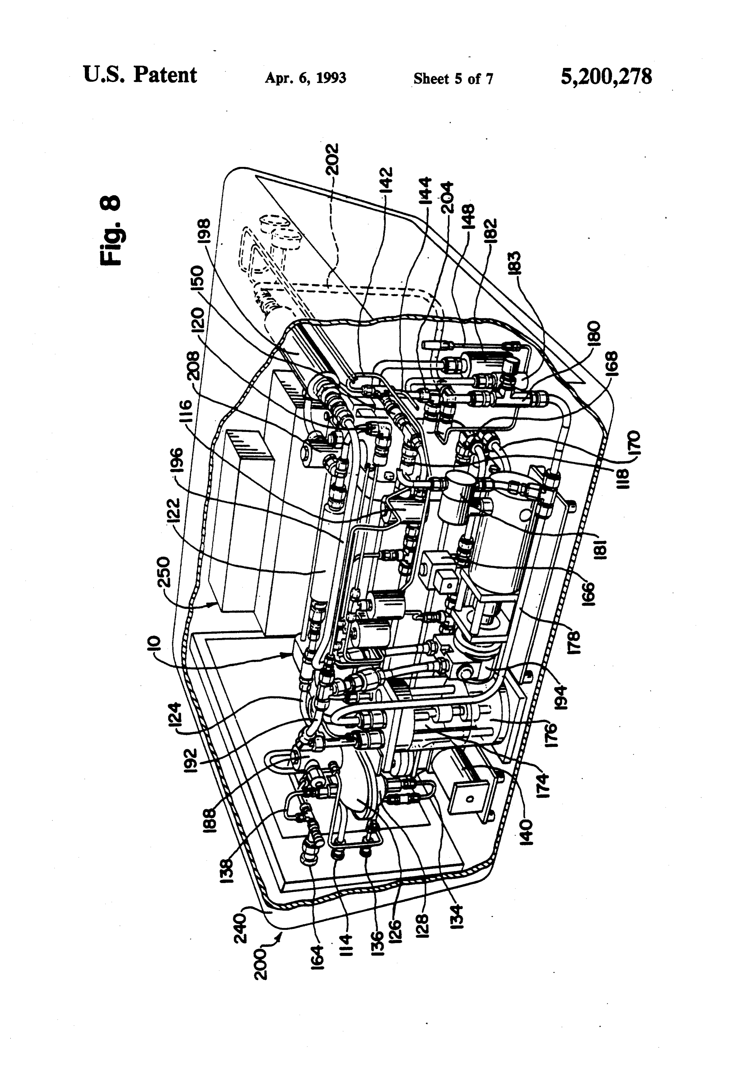
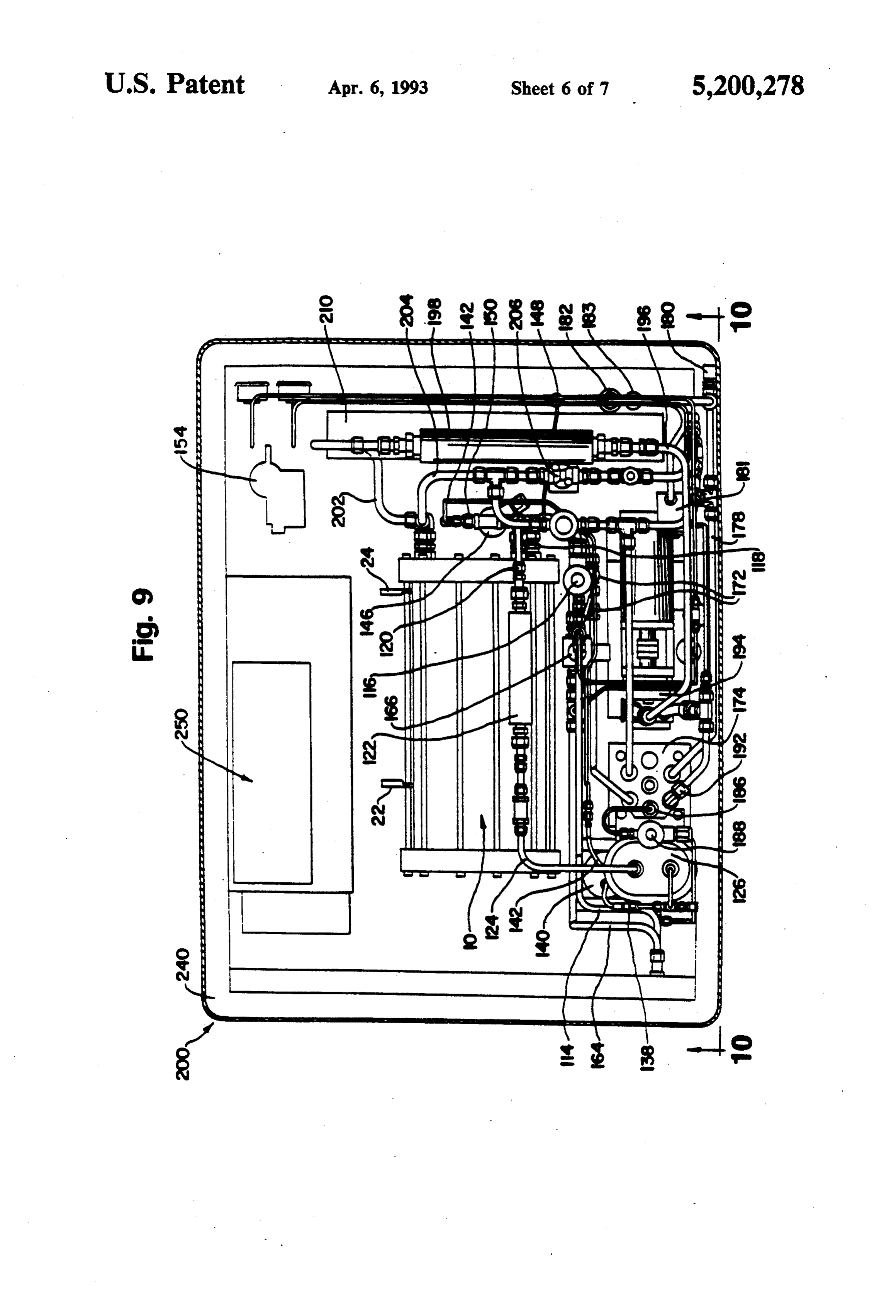
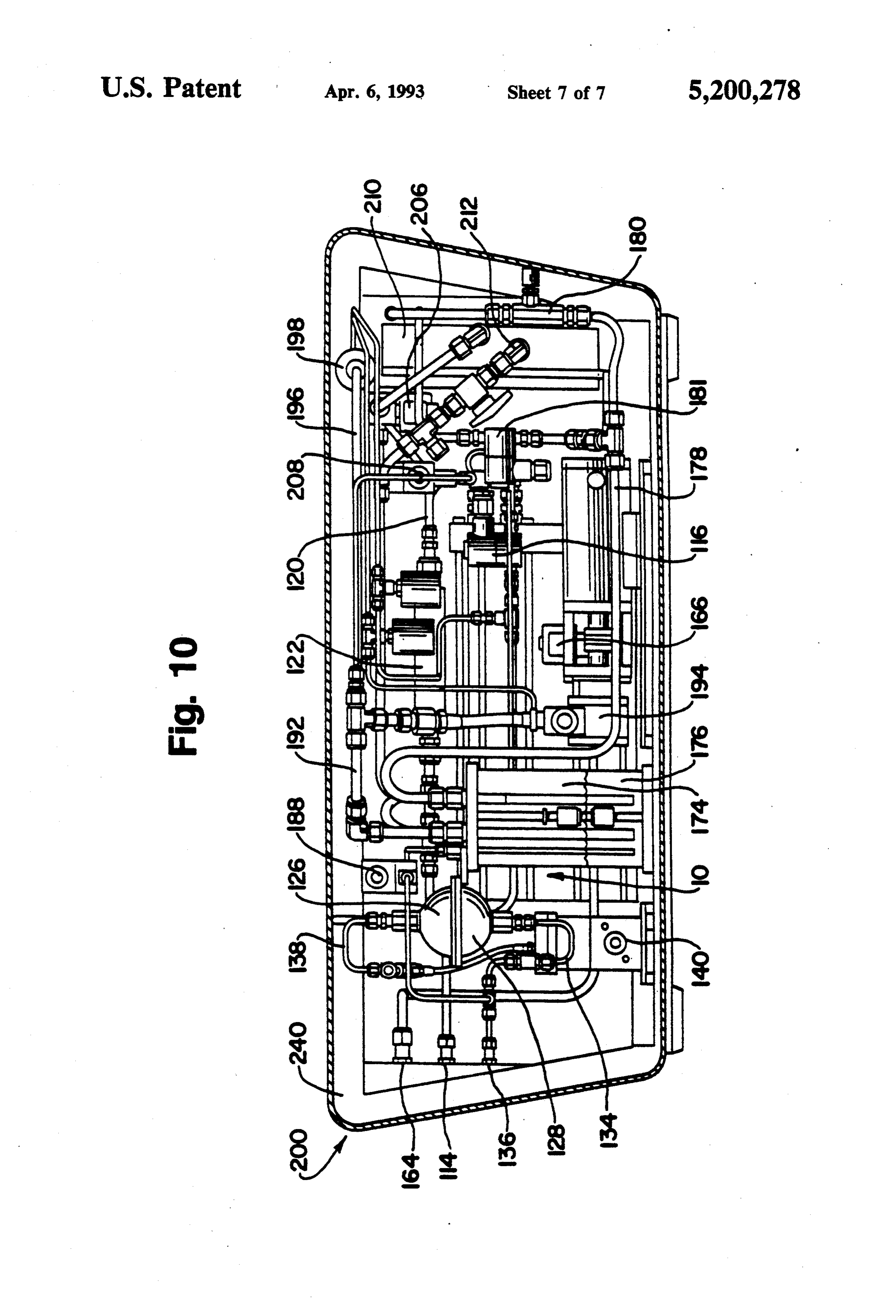
ing heat generated within the electrochemically active FIG. 5 is a schematic flow diagram of the oxidant section to produce an outlet coolant water stream. stream through the fuel cell stack of FIG. 1. The integrated fuel cell power generation system FIG. 6 is a schematic flow diagram of the combined further comprises: coolant water stream and humidification water stream a heat exchanger for removing heat from the outlet of the fuel cell stack of FIG. 1. coolant water stream to produce a chilled coolant water FIG. 7 is a schematic diagram of an integrated fuel stream, cell based electric power generation system. a water separator for removing water from the hu FIG. 8 is a perspective view of an integrated fuel cell midified oxidant stream to produce a dehumidified oxi based electric power generation system. dant stream and a removed water stream, and 10 FIG. 9 is a top plan view of the integrated fuel cell a coolant reservoir for receiving the removed water based power generation system of FIG. 8. stream from the water separator and the chilled coolant FIG. 10 is a side view of the integrated fuel cell based water stream from the heat exchanger. power generation system taken in the direction of ar The inlet coolant water stream is drawn from the rows 10-10 of FIG. 9.
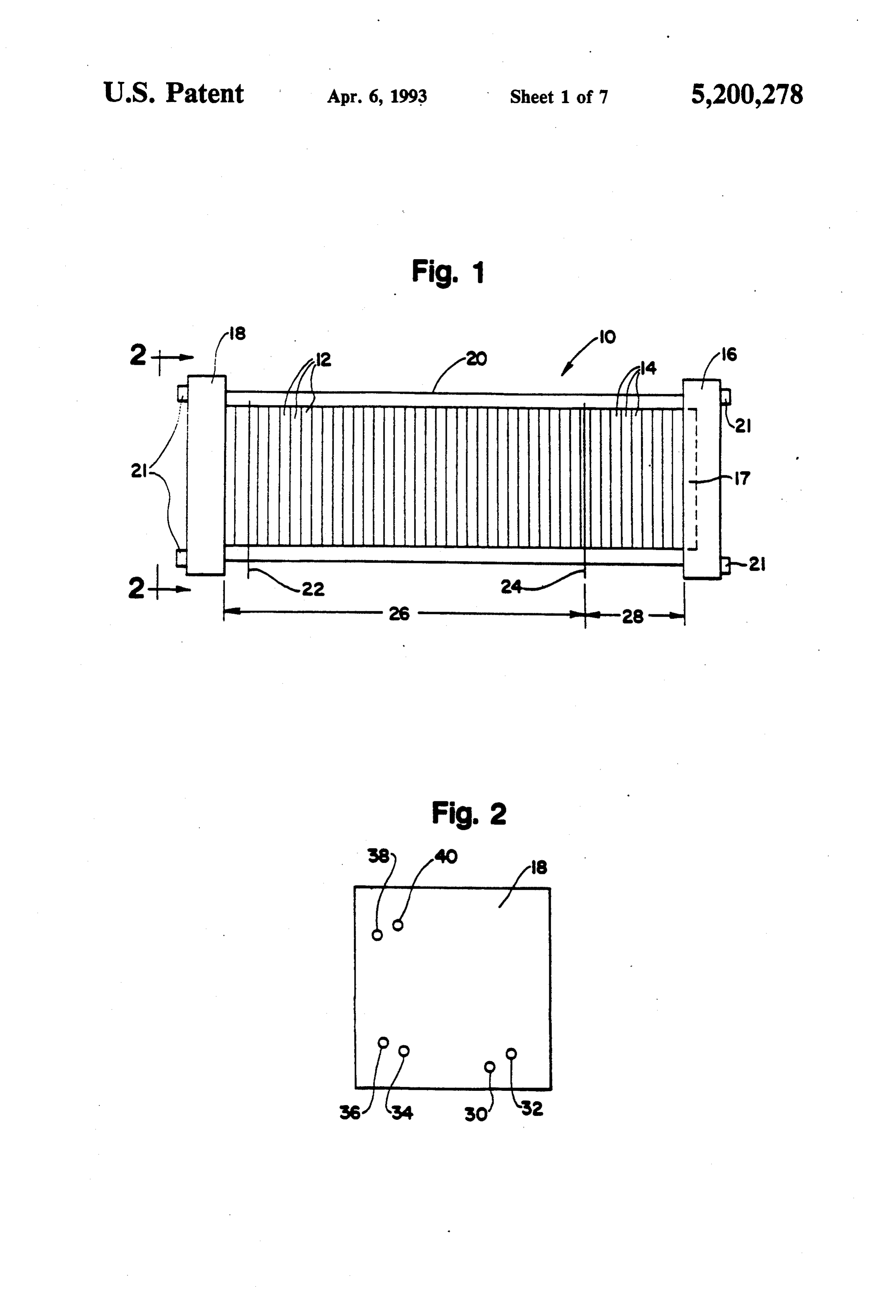
The fuel cell power generation system preferably DETAILED DESCRIPTION OF THE further comprises a second water separator for renov DRAWINGS ing water from the humidified fuel stream to produce a Turning first to FIG. 1 of the drawings, a fuel cell dehumidified fuel stream. The dehumidified fuel stream stack assembly 10 includes an electrochemically active is recirculated to the inlet fuel stream. A purge valve is 20 section 26 and a humidification section 28. Stack assem preferably included for venting the dehumidified fuel bly 10 is a modular plate and frame design, and includes stream to the atmosphere to expel contaminants accu a compression end plate 16 and a fluid end plate 18. An mulated within the dehumidified fuel stream. optional pneumatic piston 17, positioned within com In fuel cell power generation systems employing a pression end plate 16, applies uniform pressure to the substantially pure oxidant supply, the dehumidified 25 assembly to promote sealing. Bus plates 22 and 24 lo oxidant stream is recirculated to the inlet oxidant sup cated on opposite ends of active section 26 provide the ply. A purge valve is preferably included in such sys negative and positive contacts, respectively, to draw tems for venting the dehumidified oxidant stream to the current generated by the assembly to a load (not atmosphere to expel contaminants accumulated within shown). Tie rods 20 extend between end plates 16 and the dehumidified oxidant stream. 18 to retain and secure stack assembly 10 in its assem In a preferred fuel cell power generation system, the bled state with fastening nuts 21.
outlet coolant water stream supplies both the fuel hu Active section 26 includes, in addition to bus plates 22 midification water stream and the oxidant humidifica and 24, a plurality of fuel cell assemblies 12, each assem tion water stream. Most preferably, the fuel humidifica bly 12 consisting of two oppositely configured fuel tion water stream and the oxidant humidification water 35 cells, as described in more detail below. Humidification stream are integrated. section 28 includes a plurality of humidification assem In another preferred fuel cell power generation sys blies 14, each assembly 14 consisting of a fuel or oxidant tem, the water separator and the coolant reservoir are reactant flow field plate, a water flow field plate and a integral. The water within the reservoir promotes the water vapor transport membrane interposed between condensation of water from the humidified oxidant the reactant flow field plate and the water flow field stream. plate. Humidification section 28 imparts water vapor to In yet another preferred fuel cell power generation the fuel and oxidant streams that are later fed to active system, the heat exchanger comprises heat exchange section 26, thereby preventing the membranes within surfaces and air circulation means directed toward the the active section from drying out. surfaces. The system further comprises control means 45 FIG. 2 is an end view of fluid end plate 18 of stack for actuating the air circulation means when the temper assembly 10 illustrated in FIG. 1. As shown in FIG. 2, ature of the humidified oxidant stream exiting the fuel fluid end plate 18 includes fuel inlet 30, fuel outlet 32, cell stack exceeds a predetermined value. oxidant inlet 34, oxidant outlet 36, water inlet 38, and In still another preferred fuel cell power generation water outlet 40. For purposes of clarity, the fastening system, the heat exchanger further comprises valve nuts 21 at the ends of tie rods 20 (see FIG. 1) are not means for diverting the outlet coolant water stream to shown in FIG. 2.
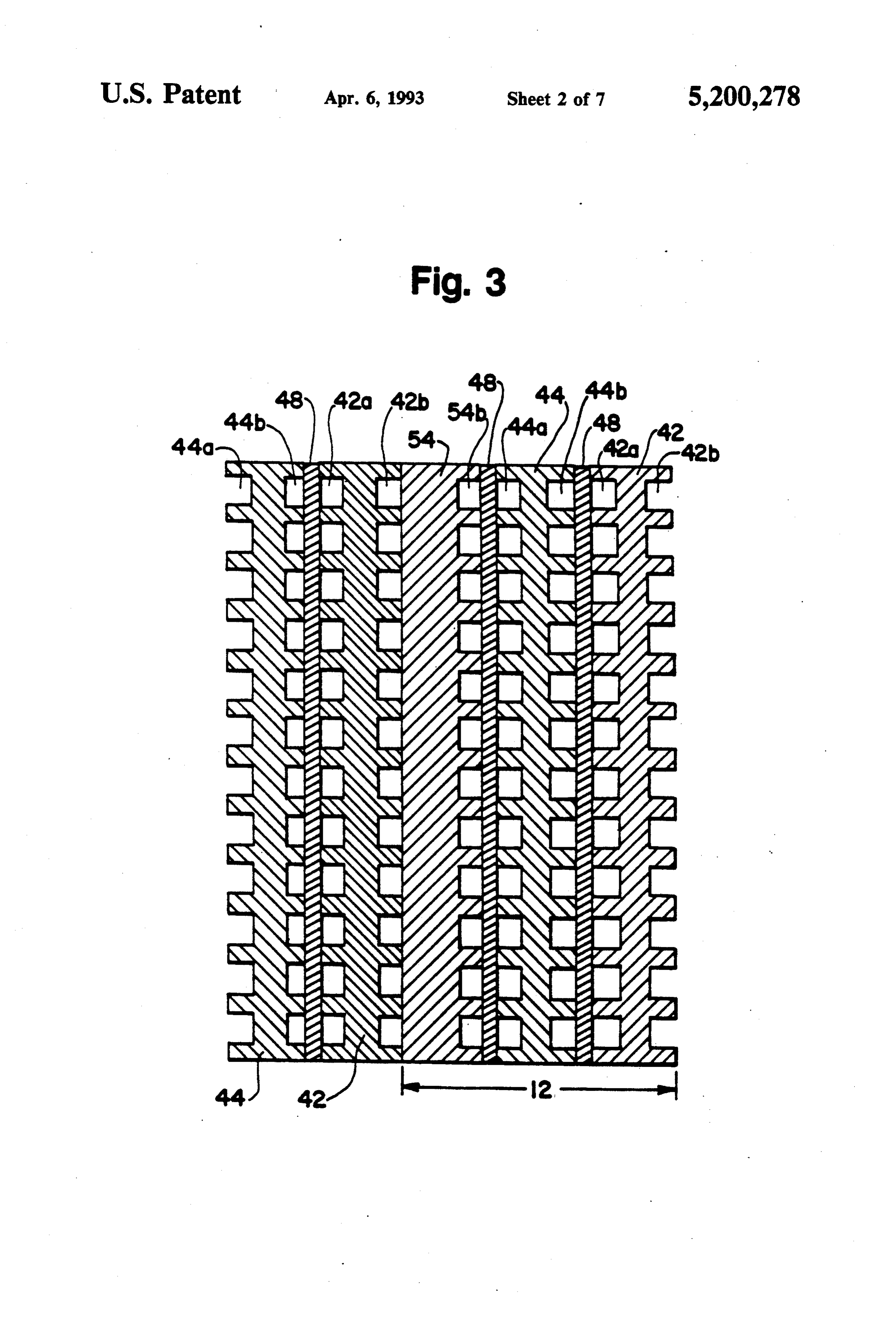
the chilled coolant water stream substantially without FIG. 3 is a sectional view of the fuel cell assemblies removing heat therefrom. The preferred heat exchanger 12 which constitute the electrochemically active sec further comprises control means for actuating the valve tion of fuel cell stack 10 of FIG. 1. As shown figured means when the temperature of the humidified oxidant 55 fuel cells. In particular, assembly 12 includes graphite stream exiting the fuel cell stack is below a predeter flow field plates 42, 44 and 54. Fuel flow field channels mined value. 44a and 44b are engraved or milled into opposite sides BRIEF DESCRIPTION OF THE DRAWINGS of plate 44. Oxidant flow field channels 42a and 54b are engraved or milled into plates 42 and 54, respectively,
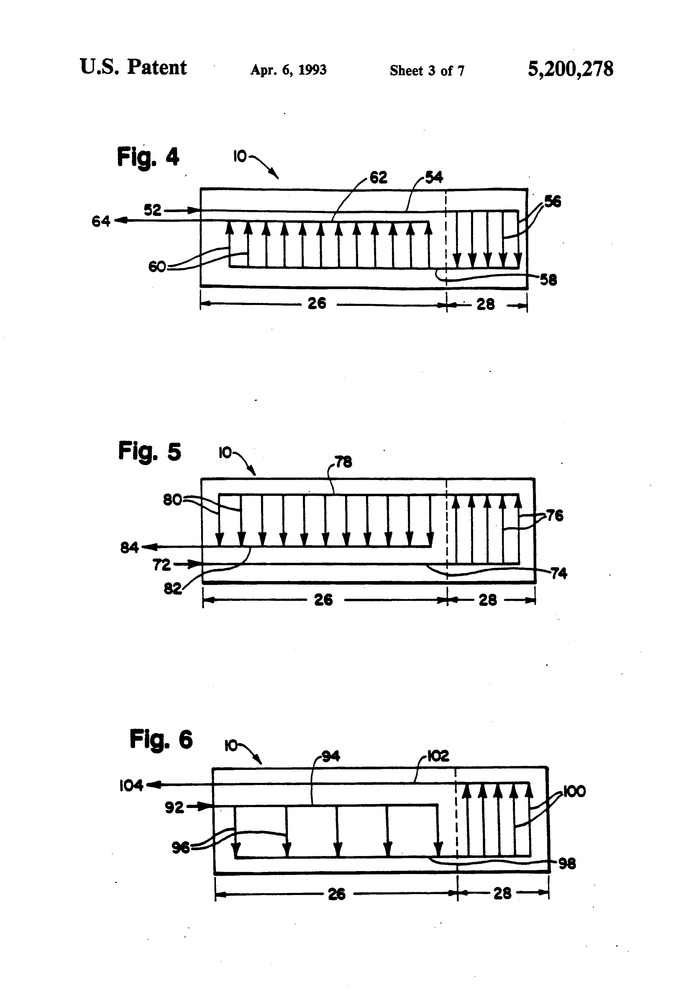
F.G. 1 is a side elevation view of a fuel cell stack as shown. Water flow field channels 42b are engraved showing the electrochemically active and humidifica or milled into plate 42 on the side opposite channels 42a, tion sections. as shown. Membrane electrode assemblies 48 are inter FIG. 2 is an end view of the fuel cell stack, taken in posed between fuel flow field channels 44b and oxidant the direction of arrows 2-2 of FIG. 1. flow field channels 42a and between fuel flow field FIG. 3 is a sectional view of a electrochemically 65 channels 44a and oxidant flow field channels 54b. active section of the fuel of FIG. 1. Membrane electrode assemblies 48 are essentially FIG. 4 is a schematic flow diagram of the fuel stream identical. Each membrane electrode assembly 48 com through the fuel cell stack of FIG. 1. prises two layers of porous electrically conductive sheet
Page 12
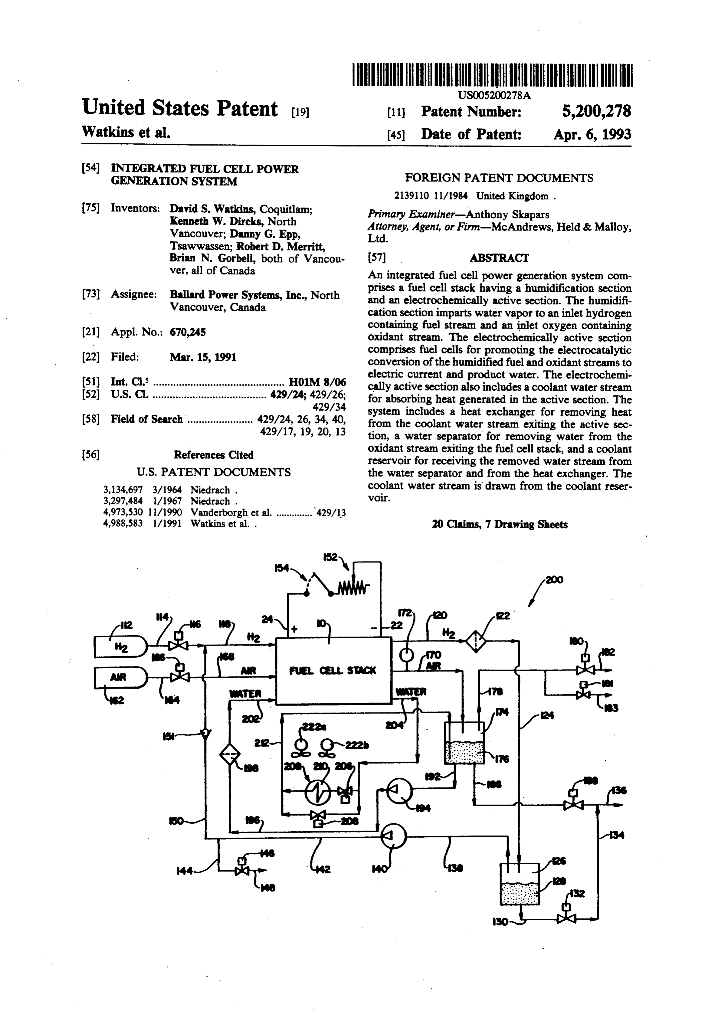
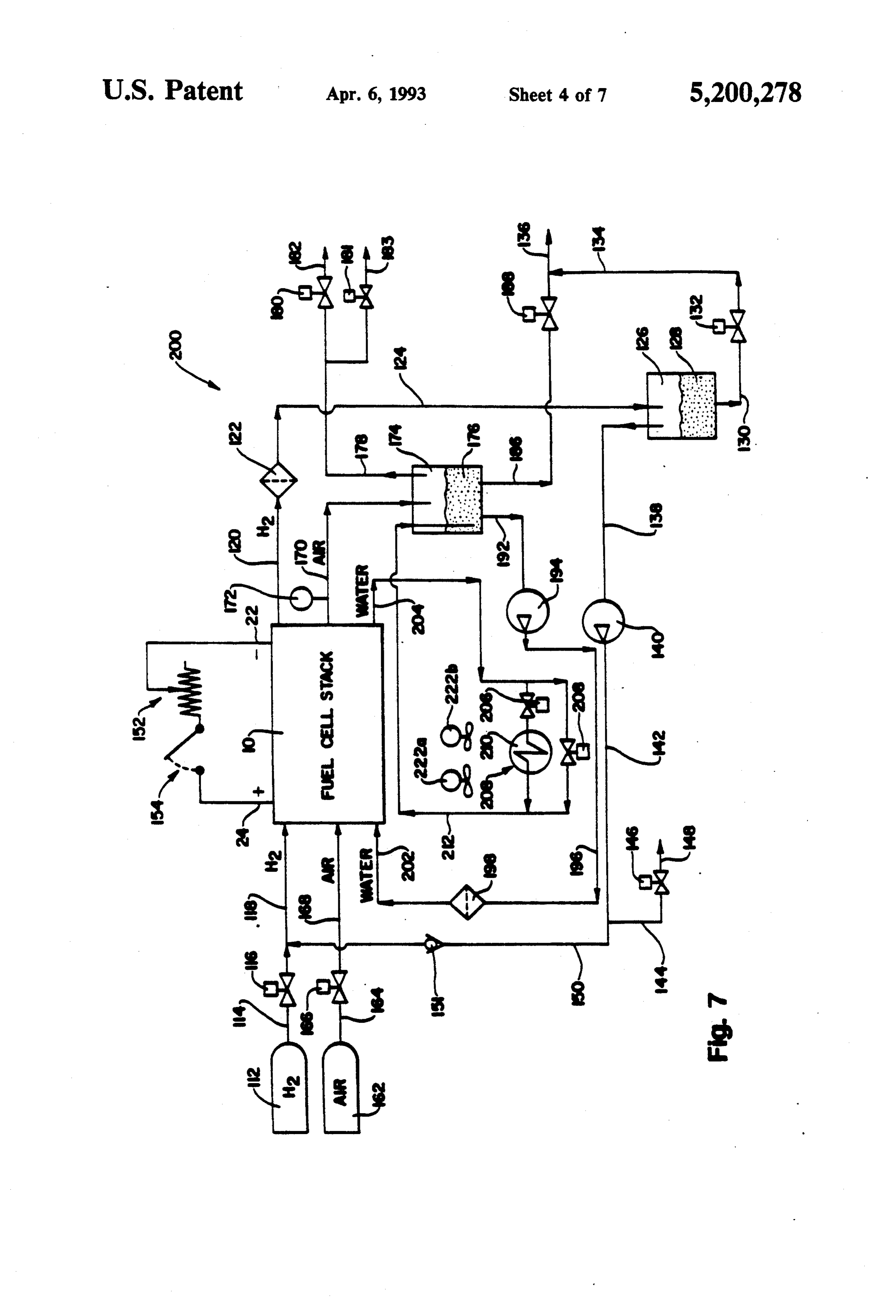
material, preferably carbon fiber paper, and a solid FIG. 7 is a schematic diagram of an integrated fuel polymer electrolyte or ion exchange membrane inter cell based electric power generation system 200 incor posed between the two layers of porous electrically porating fuel cell stack 10. Fuel cell stack 10 includes conductive sheet material. The sheet material layers are negative and positive bus plates 22 and 24, respectively, each coated with catalyst, preferably finely divided to which a circuit comprising variable load 152 and platinum, on the surfaces adjacent and in contact with contactor switch 154 is electrically connected. In addi the ion exchange membrane to render the sheet material tion to fuel cell stack 10, the integrated system includes electrochemically active. The two electrodes and ion a fuel (hydrogen) circuit, an oxidant (oxygen containing exchange membrane are heat and pressure consolidated air) circuit and a coolant (water) circuit. to form membrane electrode assemblies 48. O The fuel circuit of system 200 illustrated in FIG. 7 FIG. 4 is a schematic flow diagram of the fuel stream includes a pressurized substantially pure hydrogen sup through the active section 26 and the humidification ply 112 having fuel feed line 114 associated therewith. section 28 of fuel cell stack 10, Fuel inlet stream 52 On-off valve 116 actuates the flow of fuel from supply enters fuel cell stack 10 and traverses the extent of ac 112. Fuel inlet stream 118 enters fuel cell stack 10, tive section 26 within fuel inlet manifold 54 to bring the 15 where the fuel stream is humidified in the humidifica fuel stream up to or near cell operating temperature. tion section of stack 10, as described above, and partici From inlet manifold 54, the fuel stream passes through pates in the electrocatalytic oxidation of the fuel in the active section of stack 10. Humidified fuel outlet stream the fuel channels 56 within humidification section 28.
Water vapor exchange membranes (not shown) sepa 120 exits fuel cell stack 10 and passes through a deioniz rate fuel channels 56 from the humidification water 20 ing filter 122. Humidified fuel outlet stream 124 exiting filter 122 is fed to a water separator 126, in which a stream (not shown in FIG. 4). Humidified fuel manifold portion 58 directs the humidified fuel stream exiting channels 56 of the water from stream 124 is removed, typi to active section 26, where the humidified fuel stream cally by condensation, and the removed water is accu passes through the fuel flow field channels 60 of the fuel mulated in reservoir 128. The removed water is periodi cells to participate in the electrocatalytic oxidation of 5 cally drained from reservoir 128 through water drain lines 130, 134 and 136 by the actuation of valve 132.
the fuel to water and electric power. Fuel outlet mani Valve 132 is actuated when the level of removed water fold 62 directs the unreacted fuel stream exiting chan in reservoir 128 exceeds a predetermined value. Valve nels 60 to produce a fuel outlet stream 64. 132 is typically an integral component of reservoir 128. FIG. 5 is a schematic flow diagram of the oxidant 30 As shown in FIG.7, stream through the active section 26 and the humidifica exiting water separatorthe 126 dehumidified fuel stream 138 is recirculated by pump 140 tion section 28 of fuel cell stack 10. Oxidant inlet stream 72 enters fuel cell stack 10 and traverses the extent of through return lines 142 and 150 to fuel inlet stream 118. active section 26 within oxidant inlet manifold 74 to Return line 150 preferably includes a check valve 151. bring the oxidant stream up to or near cell operating 35 lineperiodic
intervals, the dehumidified fuel stream in purged to expel contaminants accumulated temperature. From oxidant inlet manifold 74, the fuel within the stream. Such stream passes through the oxidant channels 76 within actuation of purge valvepurging is accomplished by the humidification section 28. Water vapor exchange mem ified fuel stream to the atmospherevents 146, which the dehumid through lines 144 branes (not shown) separate oxidant channels 76 from and 148. The dehumidified fuel stream in line 142 is also the humidification water stream (not shown in FIG. 4). purged during start up to (1) expel excess water from Humidified oxidant manifold 78 directs the humidified oxidant stream exiting channels 76 to active section 26, the fuel flow channels of stack 10, and (2) unload pump 140 to facilitate its actuation.
where the humidified oxidant stream passes through the The oxidant circuit of system 200 includes a pressur oxidant flow field channels 80 of the fuel cells to partici ized air supply 162 having oxidant feed line 164 associ pate in the electrochemical reaction with the fuel. Oxi 45 ated therewith. In the illustrated embodiment of FIG.7, dant outlet manifold 82 directs the unreacted oxidant air supply 162 consists of approximately 20 percent stream exiting channels 80 to produce an oxidant outlet oxygen, and would therefore be considered a dilute stream 84. reactant supply. On-off valve 166 actuates the flow of FIG. 6 is a schematic flow diagram of the combined oxidant from supply 162. Oxidant inlet stream 168 en coolant water stream and humidification water stream ters fuel celi stack 10, where the oxidant stream is hu through the active section 26 and humidification section midified in the humidification section of stack 10, as 28, respectively, of fuel cell stack 10. Water inlet stream described above, and then participates in the electrocat 92 enters fuel cell stack 10 and is directed through water alytic oxidation of the fuel in the active section of stack inlet manifold 94 to coolant water channels 96 within 10. Oxidant outlet stream 170 exiting fuel cell stack 10 active section 26. The water stream within coolant 55 contains, in addition to the unreacted gases, water from channels 96 absorbs heat generated in active section 26 humidification and entrained product water. A thermo by the exothermic reaction of the fuel and the oxidant. couple 172 measures the temperature of oxidant outlet Water manifold 98 directs the water stream exiting stream 170 just downstream from the exit from fuel cell coolant channels 96 from active section 26 to humidifi stack 10, and actuates an air circulation system associ cation section 28. From water manifold 98, the water ated with the coolant heat exchanger, as described be stream, at approximately cell operating temperature, low.
passes through the humidification water channels 100 The humidified oxidant stream 170 exiting fuel cell within humidification section 28 to impart water vapor stack 10 is directed to water separator 174, as shown in to the fuel and oxidant streams (not shown) on the op FIG. 7. Water separator 174 removes the absorbed and posite sides of the water vapor exchange membranes 65 entrained water from stream 170, both by centrifugal (not shown). Water outlet manifold 102 directs the hu force (i.e., directing stream 170 in an arcuate path midification water stream exiting channels 100 to water against the inside wall of separator 174) and by conden outlet 104. sation. The removed water is accumulated in reservoir
Page 13
176. Reservoir 176 is preferably integral with separator The fuel circuit of system 200 includes fuel feed line 174, and the relatively cool water contained within 114 to which a pressurized substantially pure hydrogen reservoir 176 promotes the condensation of water from supply (not shown in FIGS. 8-10) is connected. The stream 170. The removed water is periodically drained fuel circuit further includes fuel inlet stream 118, which from reservoir 176 through water drain lines 186 and enters fuel cell stack 10 after merging with recirculated 136 by the actuation of control valve 188. Control valve hydrogen return line 150. The humidified fuel outlet 188 is actuated when the water level in reservoir 176 stream 120 exiting fuel cell stack 10 passes through exceeds a predetermined value. deionizing filter 122, and enters water separator 126 as Since the oxidant in the illustrated embodiment is a stream 124. In water separator 126, a portion of the dilute reactant, it is not recirculated. Instead, the dehu 10 water from stream 124 is removed by condensation, and midified oxidant stream 178 is vented to the atmosphere the removed water is accumulated in reservoir 128 through valve 180 and muffler line 182. During start up positioned directly beneath water separator 126. The (or if otherwise actuated) a second valve 181 is opened removed water drains from reservoir 128 through water to increase the oxidant flow rate through system 200. outlet line 134, and is expelled from system 200 through The opening of valve 181 purges the oxidant flow chan water drain line 136.
nels in stack 10 of excess water which may have accu As shown in FIGS. 8-10, the dehumidified fuel mulated (for example, by condensation) during shut stream 138 exiting separator 126 is recirculated through down. The opening of valve 181 causes the oxidant flow return lines 142 and 150 to fuel inlet stream 118. As to bypass valve 180, and the oxidant stream 178 is described above in connection with FIG. 7, the dehu vented to the atmosphere through muffler line 183. midified fuel stream in line 142 is purged at periodic It will be understood that in embodiments employing intervals by the actuation of purge valve 146 to vent the substantially pure oxygen as the oxidant, dehumidified dehumidified fuel stream, including any contaminants oxidant stream 178 is recirculated in a manner similar to accumulated therein, to the atmosphere through lines the recirculation of dehumidified fuel stream 138 de 144 and 148 (see FIG. 8).
scribed above. 25 The oxidant circuit of system 200 is also illustrated in The coolant circuit of system 200 derives its coolant feed line8-10.
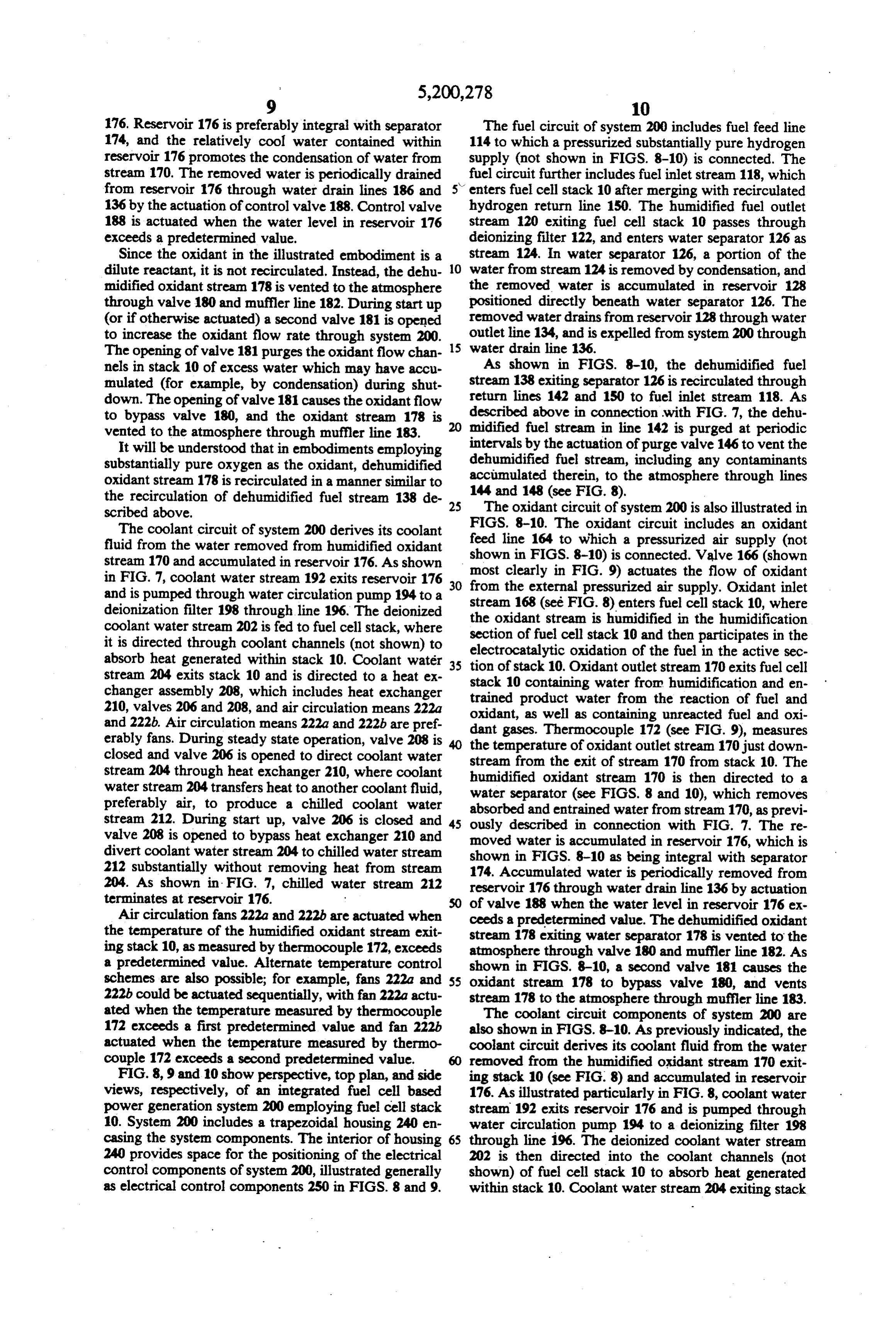
FIGS. The oxidant circuit includes an oxidant 164 to which a pressurized air supply (not fluid from the water removed from humidified oxidant stream 170 and accumulated in reservoir 176. As shown shown in FIGS. 8-10) is connected. Valve 166 (shown in FIG. 7, coolant water stream 192 exits reservoir 176 30 most clearly in FIG. 9) actuates the flow of oxidant and is pumped through water circulation pump 194 to a from the external pressurized air supply. Oxidant inlet deionization filter 198 through line 196. The deionized the stream 168 (see FIG. 8) enters fuel cell stack 10, where oxidant stream is humidified in the humidification coolant water stream 202 is fed to fuel cell stack, where section of fuel cell stack 10 and then participates in the it is directed through coolant channels (not shown) to electrocatalytic oxidation of the fuel in the active sec absorb heat generated within stack 10, Coolant water 35 tion of stack 10. Oxidant outlet stream 170 exits fuel cell stream 204 exits stack 10 and is directed to a heat ex changer assembly 208, which includes heat exchanger stack 10 containing water from humidification and en 210, valves 206 and 208, and air circulation means 222a trained product water from the reaction of fuel and oxidant, as well as containing unreacted fuel and oxi and 222b. Air circulation means 222a and 222b are pref erably fans. During steady state operation, valve 208 is dant gases. Thermocouple 172 (see FIG. 9), measures closed and valve 206 is opened to direct coolant water stream from the ofexitoxidant the temperature outlet stream 170 just down of stream 170 from stack 10. The stream 204 through heat exchanger 210, where coolant humidified oxidant stream 170 is then directed to a water stream 204 transfers heat to another coolant fluid, water separator (see FIGS. 8 and 10), which removes preferably air, to produce a chilled coolant water absorbed and entrained water from stream 170, as previ stream 212. During start up, valve 206 is closed and 45 ously described in connection with FIG. 7. The re valve 208 is opened to bypass heat exchanger 210 and moved water is accumulated in reservoir 176, which is divert coolant water stream 204 to chilled water stream shown in FIGS. 8-10 as being integral with separator 212 substantially without removing heat from stream 174. Accumulated water is periodically removed from 204. As shown in FIG. 7, chilled water stream 212 reservoir 176 through water drain line 136 by actuation terminates at reservoir 176. of valve 188 when the water level in reservoir 176 ex Air circulation fans 222a and 222b are actuated when ceeds a predetermined value. The dehumidified oxidant the temperature of the humidified oxidant stream exit stream 178 exiting water separator 178 is vented to the ing stack 10, as measured by thermocouple 172, exceeds atmosphere through valve 180 and muffler line 182. As a predetermined value. Alternate temperature control shown in FIGS. 8-10, a second valve 181 causes the schemes are also possible; for example, fans 222a and 55 oxidant stream 178 to bypass valve 180, and vents 222b could be actuated sequentially, with fan 222a actu stream 178 to the atmosphere through muffler line 183. ated when the temperature measured by thermocouple The coolant circuit components of system 200 are 172 exceeds a first predetermined value and fan 222b also shown in FIGS. 8-10. As previously indicated, the actuated when the temperature measured by thermo coolant circuit derives its coolant fluid from the water couple 172 exceeds a second predetermined value. removed from the humidified oxidant stream 170 exit FIG. 8, 9 and 10 show perspective, top plan, and side ing stack 10 (see FIG. 8) and accumulated in reservoir views, respectively, of an integrated fuel cell based 176. As illustrated particularly in FIG. 8, coolant water power generation system 200 employing fuel cell stack stream 192 exits reservoir 176 and is pumped through 10. System 200 includes a trapezoidal housing 240 en water circulation pump 194 to a deionizing filter 198 casing the system components. The interior of housing 65 through line 196. The deionized coolant water stream 240 provides space for the positioning of the electrical 202 is then directed into the coolant channels (not control components of system 200, illustrated generally shown) of fuel cell stack 10 to absorb heat generated as electrical control components 250 in FIGS. 8 and 9. within stack 10. Coolant water stream 204 exiting stack
Page 14
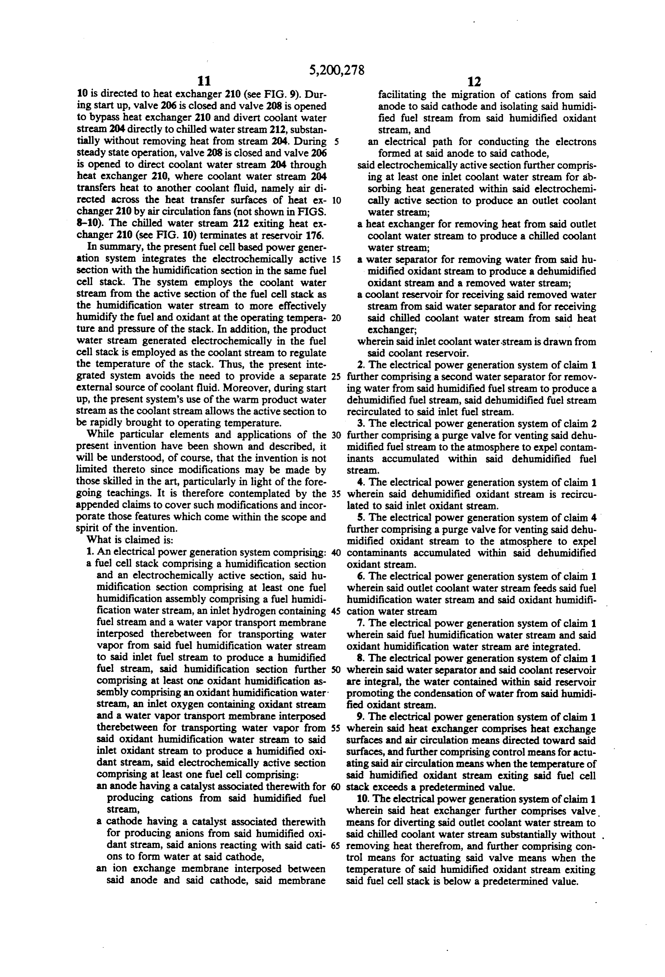
10 is directed to heat exchanger 210 (see FIG. 9). Dur facilitating the migration of cations from said ing start up, valve 206 is closed and valve 208 is opened anode to said cathode and isolating said humidi to bypass heat exchanger 210 and divert coolant water fied fuel stream from said humidified oxidant stream 204 directly to chilled water stream 212, substan stream, and tially without removing heat from stream 204. During 5 an electrical path for conducting the electrons steady state operation, valve 208 is closed and valve 206 formed at said anode to said cathode, is opened to direct coolant water stream 204 through said electrochemically active section further compris heat exchanger 210, where coolant water stream 204 ing at least one inlet coolant water stream for ab transfers heat to another coolant fluid, namely air di sorbing heat generated within said electrochemi rected across the heat transfer surfaces of heat ex 10 cally active section to produce an outlet coolant changer 210 by air circulation fans (not shown in FIGS. water stream;
8-10). The chilled water stream 212 exiting heat ex a heat exchanger for removing heat from said outlet changer 210 (see FIG. 10) terminates at reservoir 176. coolant water stream to produce a chilled coolant In summary, the present fuel cell based power gener water stream;
ation system integrates the electrochemically active a water separator for removing water from said hu section with the humidification section in the same fuel midified oxidant stream to produce a dehumidified cell stack. The system employs the coolant water oxidant stream and a removed water stream; stream from the active section of the fuel cell stack as a coolant reservoir for receiving said removed water the humidification water stream to more effectively stream from said water separator and for receiving humidify the fuel and oxidant at the operating tempera 20 said chilled coolant water stream from said heat ture and pressure of the stack. In addition, the product exchanger;
water stream generated electrochemically in the fuel wherein said inlet coolant water-stream is drawn from cell stack is employed as the coolant stream to regulate said coolant reservoir. the temperature of the stack. Thus, the present inte 2. The electrical power generation system of claim 1 grated system avoids the need to provide a separate 25 further comprising a second water separator for remov external source of coolant fluid. Moreover, during start ing water from said humidified fuel stream to produce a up, the present system's use of the warm product water dehumidified fuel stream, said dehumidified fuel stream stream as the coolant stream allows the active section to recirculated to said inlet fuel stream. be rapidly brought to operating temperature. 3. The electrical power generation system of claim 2 While particular elements and applications of the 30 further comprising a purge valve for venting said dehu present invention have been shown and described, it midified fuel stream to the atmosphere to expel contam will be understood, of course, that the invention is not inants accumulated within said dehumidified fuel limited thereto since modifications may be made by stream.
those skilled in the art, particularly in light of the fore 4. The electrical power generation system of claim 1 going teachings. It is therefore contemplated by the 35 wherein said dehumidified oxidant stream is recircu appended claims to cover such modifications and incor lated to said inlet oxidant stream. porate those features which come within the scope and 5. The electrical power generation system of claim 4 spirit of the invention. further comprising a purge valve for venting said dehu What is claimed is: midified oxidant stream to the atmosphere to expel 1. An electrical power generation system comprising: contaminants accumulated within said dehumidified a fuel cell stack comprising a humidification section oxidant stream.
and an electrochemically active section, said hu 6. The electrical power generation system of claim 1 midification section comprising at least one fuel wherein said outlet coolant water stream feeds said fuel humidification assembly comprising a fuel humidi humidification water stream and said oxidant humidifi fication water stream, an inlet hydrogen containing 45 cation water stream fuel stream and a water vapor transport membrane 7. The electrical power generation system of claim 1 interposed therebetween for transporting water wherein said fuel humidification water stream and said vapor from said fuel humidification water stream oxidant humidification water stream are integrated. to said inlet fuel stream to produce a humidified 8. The electrical power generation system of claim 1 fuel stream, said humidification section further wherein said water separator and said coolant reservoir comprising at least one oxidant humidification as are integral, the water contained within said reservoir sembly comprising an oxidant humidification water promoting the condensation of water from said humidi stream, an inlet oxygen containing oxidant stream fied oxidant stream.
and a water vapor transport membrane interposed 9. The electrical power generation system of claim 1 therebetween for transporting water vapor from 55 wherein said heat exchanger comprises heat exchange said oxidant humidification water stream to said surfaces and air circulation means directed toward said inlet oxidant stream to produce a humidified oxi surfaces, and further comprising control means for actu dant stream, said electrochemically active section ating said air circulation means when the temperature of comprising at least one fuel cell comprising: said humidified oxidant stream exiting said fuel cell an anode having a catalyst associated therewith for stack exceeds a predetermined value.
producing cations from said humidified fuel 10. The electrical power generation system of claim 1 stream, wherein said heat exchanger further comprises valve a cathode having a catalyst associated therewith means for diverting said outlet coolant water stream to for producing anions from said humidified oxi said chilled coolant water stream substantially without . dant stream, said anions reacting with said cati 65 removing heat therefrom, and further comprising con ons to form water at said cathode, trol means for actuating said valve means when the an ion exchange membrane interposed between temperature of said humidified oxidant stream exiting said anode and said cathode, said membrane said fuel cell stack is below a predetermined value.
Page 15
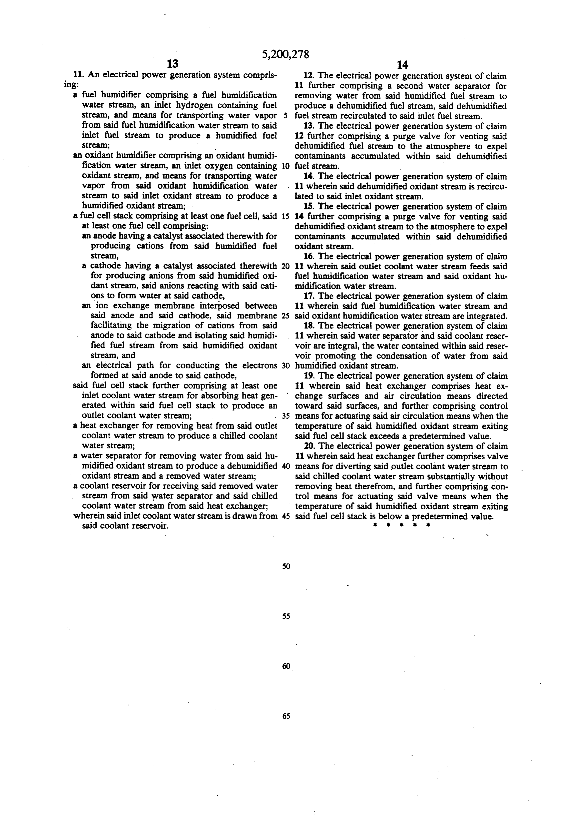
11. An electrical power generation system compris 12. The electrical power generation system of claim ing: 11 further comprising a second water separator for a fuel humidifier comprising a fuel humidification removing water from said humidified fuel stream to water stream, an inlet hydrogen containing fuel produce a dehumidified fuel stream, said dehumidified stream, and means for transporting water vapor 5 fuel stream recirculated to said inlet fuel stream. from said fuel humidification water stream to said 13. The electrical power generation system of claim inlet fuel stream to produce a humidified fuel 12 further comprising a purge valve for venting said stream; dehumidified fuel stream to the atmosphere to expel an oxidant humidifier comprising an oxidant humidi contaminants accumulated within said dehumidified fication water stream, an inlet oxygen containing 10 fuel stream.
oxidant stream, and means for transporting water 14. The electrical power generation system of claim vapor from said oxidant humidification water . 11 wherein said dehumidified oxidant stream is recircu stream to said inlet oxidant stream to produce a lated to said inlet oxidant stream.
humidified oxidant stream; 15. The electrical power generation system of claim a fuel cell stack comprising at least one fuel cell, said 15 14 further comprising a purge valve for venting said at least one fuel cell comprising: dehumidified oxidant stream to the atmosphere to expel an anode having a catalyst associated therewith for contaminants accumulated within said dehumidified producing cations from said humidified fuel oxidant stream.
Stream, 16. The electrical power generation system of claim a cathode having a catalyst associated therewith 11 wherein said outlet coolant water stream feeds said for producing anions from said humidified oxi fuel humidification water stream and said oxidant hu dant stream, said anions reacting with said cati midification water stream.
ons to form water at said cathode, 17. The electrical power generation system of claim an ion exchange membrane interposed between 11 wherein said fuel humidification water stream and said anode and said cathode, said membrane 25 said oxidant humidification water stream are integrated. facilitating the migration of cations from said 18. The electrical power generation system of claim anode to said cathode and isolating said humidi 11 wherein said water separator and said coolant reser fied fuel stream from said humidified oxidant voir are integral, the water contained within said reser stream, and voir promoting the condensation of water from said an electrical path for conducting the electrons humidified oxidant stream.
formed at said anode to said cathode, 19. The electrical power generation system of claim said fuel cell stack further comprising at least one 11 wherein said heat exchanger comprises heat ex inlet coolant water stream for absorbing heat gen change surfaces and air circulation means directed erated within said fuel cell stack to produce an toward said surfaces, and further comprising control outlet coolant water stream; 35 means for actuating said air circulation means when the a heat exchanger for removing heat from said outlet temperature of said humidified oxidant stream exiting coolant water stream to produce a chilled coolant said fuel cell stack exceeds a predetermined value. water stream; 20. The electrical power generation system of claim a water separator for removing water from said hu 11 wherein said heat exchanger further comprises valve midified oxidant stream to produce a dehumidified means for diverting said outlet coolant water stream to oxidant stream and a removed water stream; said chilled coolant water stream substantially without a coolant reservoir for receiving said removed water removing heat therefrom, and further comprising con stream from said water separator and said chilled trol means for actuating said valve means when the coolant water stream from said heat exchanger; temperature of said humidified oxidant stream exiting wherein said inlet coolant water stream is drawn from 45 said fuel cell stack is below a predetermined value. said coolant reservoir.
Page 16
UNITED STATES PATENT ANDTRADEMARK OFFICE
CERTIFICATE OF CORRECTION
INVENTOR(S) : David S. Watkins, et all
it is certified that error appears in the above-indentified patent and that said Letters Patent is hereby Corrected as shown below:
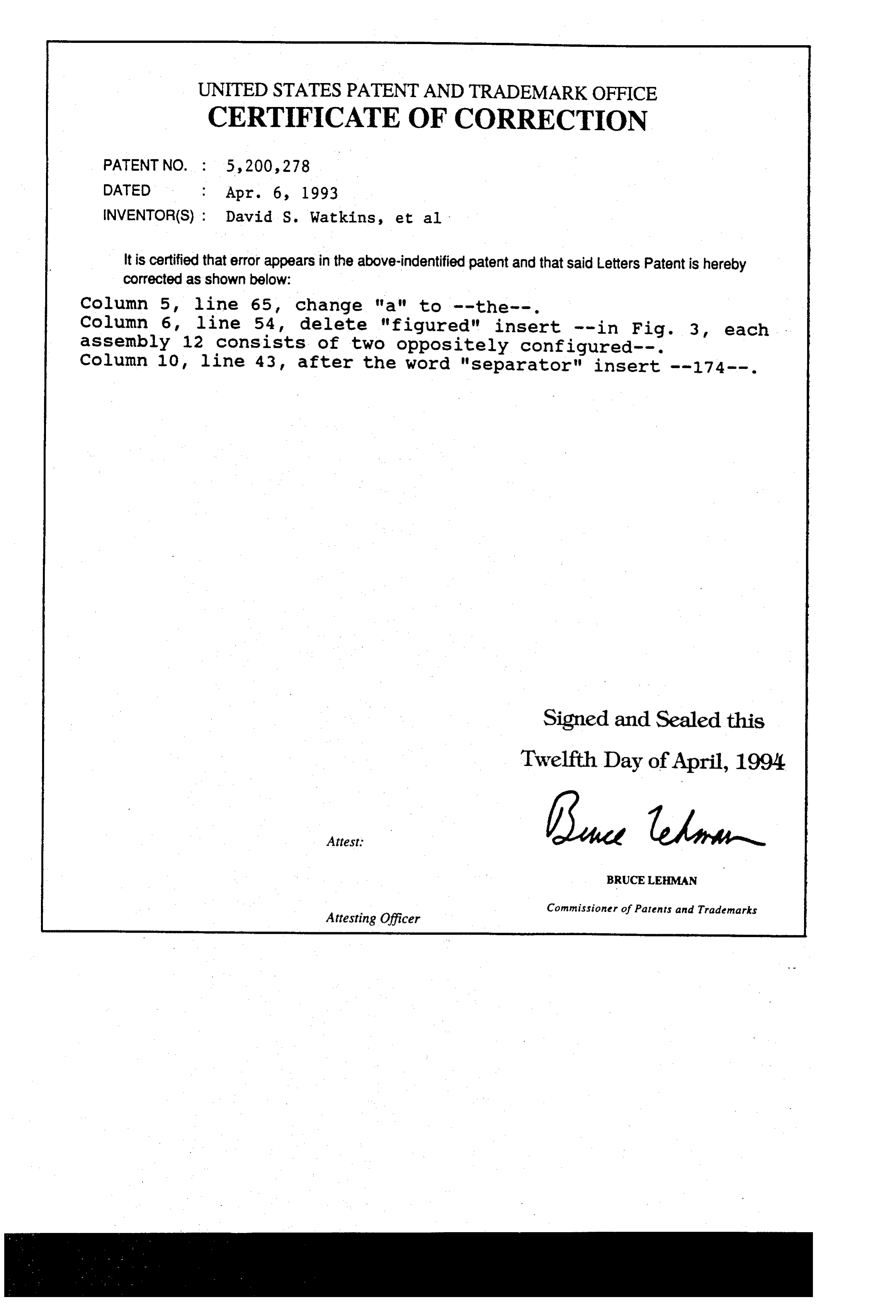
Column 5, line 65, change "a" to --the--. Column 6, line 54, delete "figured" insert -- in Fig. 3, each assembly 12 consists of two oppositely configured--. Column 10, line 43, after the word "separator" insert --174--.
Signed and Sealed this
Twelfth Day of April, 1994
(a teen
BRUCE LEHMAN
Commissioner of Patents and Trademarks
Attesting Officer
Provenance
- Collection
- Cited prior art
- Original PDF
- patentimages.storage.googleapis.com →
- Filed
- 1991-03-15
- Pages
- 16
- Method
- pdftotext (the PDF's own text layer) + pdftoppm 300dpi page scans
- Source
- Google Patents bibliographic record
- Granted
- 1993-04-06
- Inventors
- David S. Watkins; Kenneth W. Dircks; Danny G. Epp; Robert D. Merritt; Brian N. Gorbell; Ballard Power Systems Inc
- Transcribed from
- patentimages.storage.googleapis.com →