patent · US4080487
Process for cooling molten carbonate fuel cell stacks and apparatus therefor
21 March 1978
Page 1 — bibliographic record
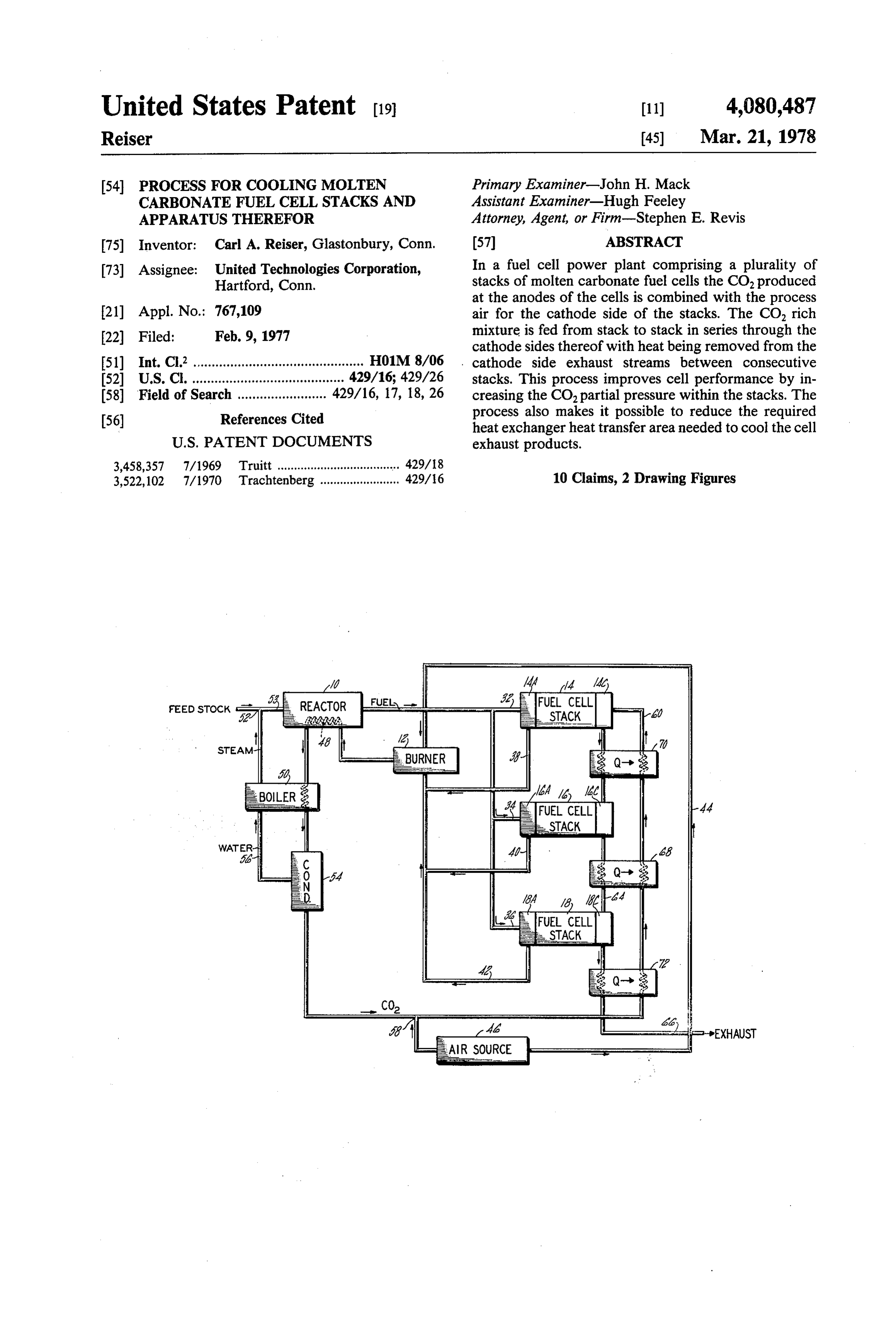
United States Patent (19) 11) 4,080,487 Reiser 45) Mar. 21, 1978 54 PROCESS FOR COOLING MOLTEN Primary Examiner-John H. Mack CARBONATEFUEL CELL STACKS AND Assistant Examiner-Hugh Feeley
APPARATUS THEREFOR Attorney, Agent, or Firm-Stephen E. Revis 75) Inventor: Carl A. Reiser, Glastonbury, Conn. (57) ABSTRACT 73) Assignee: United Technologies Corporation, In a fuel cell power plant comprising a plurality of Hartford, Conn. stacks of molten carbonate fuel cells the CO produced at the anodes of the cells is combined with the process 21 Appl. No.: 767,109 air for the cathode side of the stacks. The CO, rich Filed: Feb. 9, 1977 mixture is fed from stack to stack in series through the 22 File eb. 9, cathode sides thereof with heat being removed from the 51) Int. C.’.............................................. H01M. 8/06 cathode side exhaust streams between consecutive 52 U.S. C. ................. o O- 429/16; 429/26 stacks. This process improves cell performance by in (58) Field of Search ..... 429/16, 17, 18, 26 creasing the CO, partial pressure within the stacks. The process also makes it possible to reduce the required (56) References Cited heat exchanger heat transfer area needed to cool the cell
3,458,357 7/1969 Truitt ...................................... 429/18 3,522,102 7/1970 Trachtenberg ........................ 429/6 10 Claims, 2 Drawing Figures
BURNER
Page 2
Drawing sheet — no readable text.
Page 3
Drawing sheet — no readable text.
Page 4
cell reactants. With this method the air, enriched with
PROCESS FOR COOLNG MOLTEN CARBONATE CO, from the anode exhaust, is divided into equal por FUEL CELL STACKS AND APPARATUS tions and passes in parallel through the cathode side of THEREFOR the stacks. This cooling method is hereinafter referred BACKGROUND OF THE INVENTION to assingle pass process air cooling. (Process air, as that 1. Field of the Invention term is used herein, simply means the air used in the
This invention relates to molten carbonate fuel cell electrochemical process.) Single pass process air cool power plants. ing has the drawback that, for a system with "n" stacks, 2. Description of the Prior Art the process air stream for each stack is limited to 10 receiving only 1/n times the amount of CO2 produced
Molten carbonate fuel cells are well know in the art.
These cells comprise an ion conducting molten carbon by the stacks. Diluting this amount of CO2 with the necessary amount of air for cooling results in CO2 ate electrolyte sandwiched between an anode and cath partial ode electrode. Cells of this type are somewhat more resultingpressures which are often less than satisfactory, fully described in commonly owned U.S. Pat. Nos. 15 cially attractive. plant which may not be commer in a power 3,878,296 Vine et al. and 3,615,839 Thompson et al. From a fuel cell performance point of view, the best The design of any commercial power plant has as one method for cooling the fuel cells is with a cooling of its major considerations the cost per kilowatt of elec stream which passes through the cells but is separate tricity produced. Cost per kilowatt includes both capital expense and operating expense. Obviously, it is ex 20 from the process air stream. This permits the lowest tremely important that the fuel cells operate efficiently, possible airflow rate at the cathode since the process air but the cost for obtaining high efficiency cannot be is not needed for cooling; CO, partial pressure is there excessive. Cell efficiency is directly tied to the suitabil fore maximized. This method, however, requires sepa ity of the fuel and oxidant compositions supplied to the rate cooling fluid passageways within the stack, which anode and cathode, respectively. The anode reaction in 25 adds considerable expense to the stacks and is a complex a molten carbonate fuel cell is shown by the following technical problem.
equation: SUMMARY OF THE INVENTION CO + H – CO + HO + 2e One object of the present invention is a molten car
bonate fuel cell system which is economically attrac
The cathode reaction is shown by the following equa tive.
tion: Another object of the present invention is a method O + CO, +2e.--> CO, for cooling molten carbonate fuel cells which is eco nomically attractive.
The unique difference between the anode and cathode 35 power Accordingly, a process for operating a fuel cell reactions of molten carbonate fuel cells as compared to carbonate plant, including a plurality of stacks of molten the anode and cathode reactions of more conventional fuel cells, comprises the steps of introducing acid or base electrolyte fuel cells is that the molten the CO, produced at the anode side of the stacks into the carbonate cells consume carbon dioxide at the cathode cathode side process air supply upstream of the stacks, and produce carbon dioxide at the anode. feeding the CO, rich process air from stack to stack in Good performance (high current density at high cell series, and removing heat from the cathode side exhaust voltage) in a molten carbonate fuel cell necessarily re stream between the stacks.
quires reasonably high partial pressures of both carbon In the process of the present invention (hereinafter dioxide and oxygen at the cathode. It is generally referred to as "multi-pass process air cooling') the agreed that a practical molten carbonate fuel cell system 45 quantity of air needed for cooling the plurality of stacks requires the carbon dioxide produced at the anode be in the series is nearly the same as that needed for cooling returned to the cathode since the air used as the oxidant each stack in a single pass process air cooling system. at the cathode does not naturally contain enough car This is made possible by removing heat from the cath bon dioxide for efficient performance. The aforemen ode exhaust stream between the stacks. In addition note tioned Thompson et al patent discloses one technique 50 that, in the system of the present invention, all of the for accomplishing this task: transferring the CO, in the COproduced at the anodes of all the stacks is present in anode exhaust to the cathode inlet air stream by means the process air stream supplied to the cathode side of of a membrane selectively permeable to CO. Another the first stack in the series. The first stack in the series technique is to combine the entire anode exhaust with will, therefore, have a considerably higher CO, partial the cathode inlet air stream, such as shown in U.S. Pat. 55 pressure than any stack of a single pass process air cool No. 3,436,271 Cole et al. Ideally, it is desirable to have twice as much CO as Oin the oxidant stream since two ing system. Furthermore, in a single pass process air cooling system any CO, not consumed in each stack is moles of CO, are consumed for each mole of O. lost; in the present invention the unconsumed CO, from Another important consideration in the design of the first stack commercially feasible molten carbonate fuel cell power 60 on), therebyis made available to succeeding tacks (and plants is cell cooling. Molten carbonate cells typically so boosting CO partial pressure through operate at temperatures of about 1200' F. Considerable out the system. It is believed that in many instances, quantities of heat are produced during operation which depending on the number of stacks in series and other must be removed to prevent overheating of the cells. factors, this will result in an improvement in cell perfor Cooling the cells in an economical manner can make the 65 mance coupled with either a reduction in equipment difference between commercial success and failure. cost, or an increase in equipment cost which may be One method of cooling a plurality of molten carbon more than offset by improved performance. However, ate fuel cell stacks is to use the process air stream for as will hereinafter be explained, the cost of adding addi cooling as well as for delivery of the cathode side fuel tional stacks (due to required additional manifolding,
Page 5
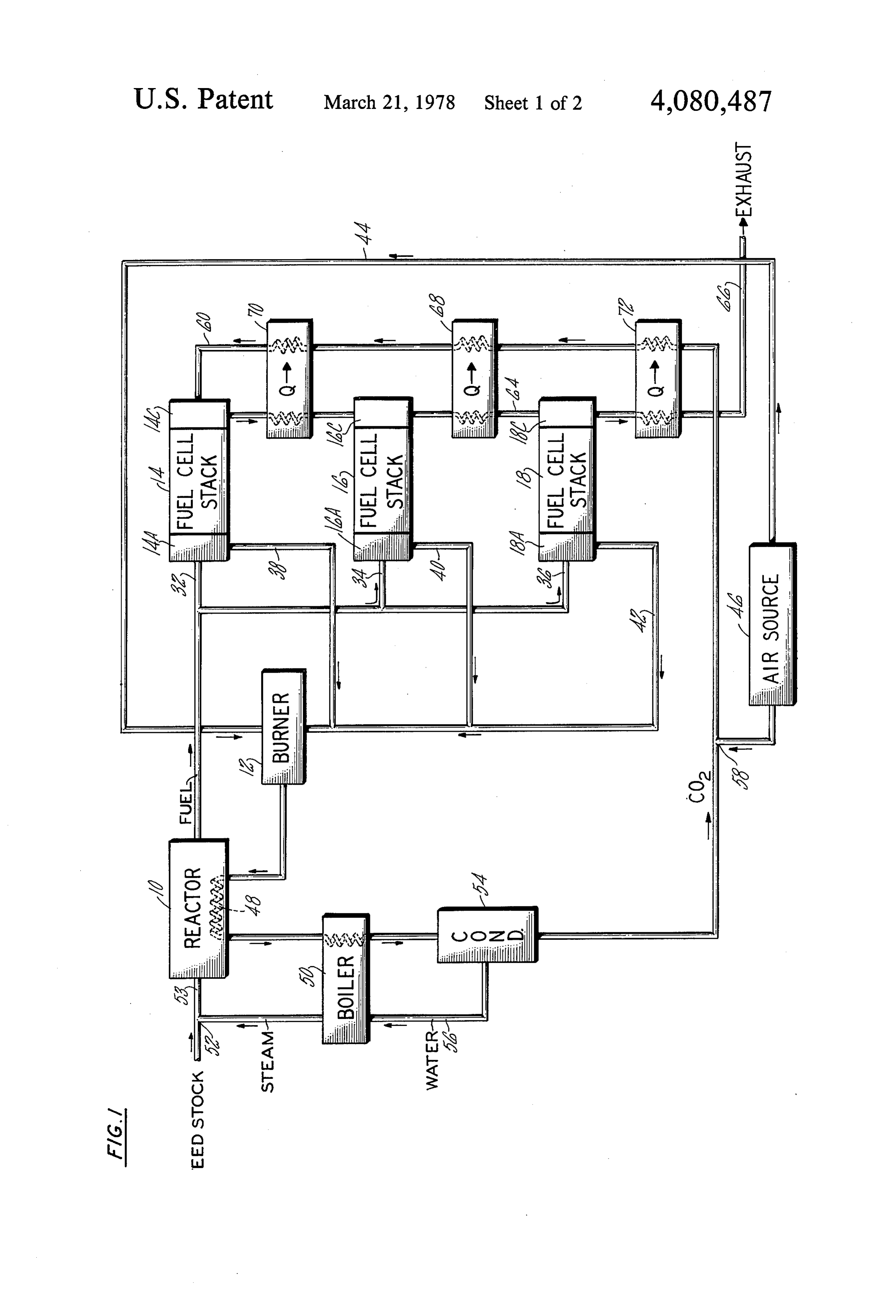
controls, heat exchangers, etc.) may, at some point, The power plant also includes a steam reforming override any resulting performance gain. reactor 10. In the reactor 10 hydrogen is formed by Economic and performance advantages or disadvan reacting steam and a suitable carbonaceous feedstock, tages of the present invention as compared to, for exam such as naphtha or natural gas, in the presence of a ple, single pass process air cooling, will, in the final suitable catalyst such as nickel. Heat for the endother analysis, depend upon the constraints placed upon the mic reaction is supplied by a burner 12. system such as the desired temperature gradient across In operation, reformed fuel (essentially hydrogen) the cells, the pressures of the reactants, hydrogen utili from the reactor 10 is fed in parallel to the stacks 14, 16, zation levels, thermal efficiency of the power section, and 18 via conduits 32, 34, and 36, respectively. The fuel type of feedstock used, and equipment cost. It is be 10 passes through the anode sides 14A, 16A, and 18A of lieved that, when all things are taken into consideration, the stacks, reacting at the anode electrodes 20 to pro there will be an optimum number of stacks to be con duce water, carbon dioxide, electricity and heat. The nected in series for any given set of constraints. Gener anode compartment exhaust, which includes uncon ally speaking, however, if the process air flow rate is 15 sumed hydrogen, carbon dioxide, and water, leaves the kept at the minimum needed to maintain an acceptable stacks via the conduits 38, 40, and 42 and are fed to the temperature gradient across all the stacks, the optimum burner 12.
number of stacks will be determined by the point at In the burner 12 the unconsumed hydrogen in the which the addition of another stack adds such a small anode exhaust burns with air supplied to the burner via performance benefit that the additional expense associ 20 aburner conduit 44 from a suitable source 46. If necessary, the may also have a separate fuel supply. The heat ated with the added stack is not warranted.
produced is transferred to the reactor 10 as represented
BRIEF DESCRIPTION OF THE DRAWING by the heat exchanger 48. Additional heat in the burner exhaust is used to convert water to steam in a boiler 50.
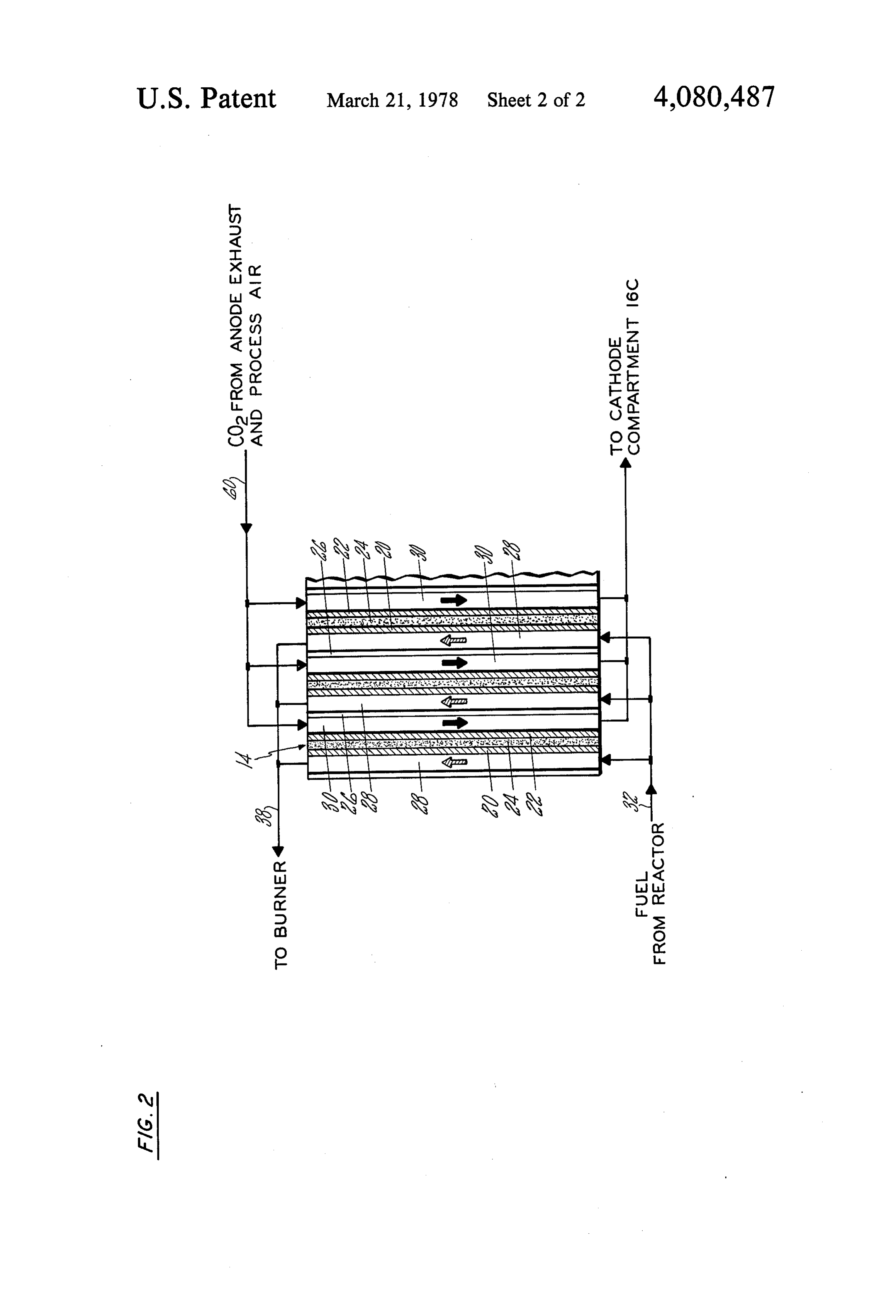
FIG. 1 is a schematic of a power plant according to The steam from the boiler 50 is combined with the the present invention. 25 feedstock as at 52 and is introduced into the steam re FIG. 2 is a cross sectional view, partly schematic, showing one of the fuel cell stacks of FIG. 1 in more forming reactor 10 via a conduit 53. The water in the anode exhaust is removed in a condenser 54 and is fed to detail.
the boiler 50 via a conduit 56. The anode exhaust, which
DESCRIPTION OF THE PREFERRED still includes the carbon dioxide produced in the stacks, EMBODIMENT 30 is thereupon combined at 58 with the process air from the air supply 46 for use at the cathode electrodes of the
Referring to FIG. 1, a schematic of a fuel cell power cells.
plant according to the present invention is shown. The The process air mixed with the anode exhaust and power section is shown as comprising three stacks of therefore rich in CO, (the mixture hereinafter referred fuel cells, the stacks having the reference numerals 14, 35 to as the cathode feed) is fed in series through the cath 16, and 18, respectively. Each stack comprises a plural ode sides 14C, 16C, and 8C of the stacks via the con ity of molten carbonate fuel cells connected electrically duits 60, 62, and 64, respectively. At the cathode elec in series. Although three stacks are shown, this is by trodes of the stacks 14, 16, and 18, the oxygen and CO, way of example only, the invention not being limited in the process air and the CO2 from the anode exhaust thereto. 40 react at the cathode electrodes according to equation Referring to FIG. 2, a more detailed representation of (2) above. The depleted cathode feed is exhausted from the stack 14 is shown. The stacks 16 and 18 may be the last stack in the series and vented to atmosphere as identical to the stack 14. For the purposes of simplicity, represented by the arrow 66.
the stack of FIG. 2 comprises only three cells; but, in an As the cathode feed passes through each stack it picks actual power plant each stack may contain upward of 45 up heat thereby cooling the stack. This heat is removed 100 or more cells. Preferably (but not necessarily), each between stacks by passing the stack cathode exhaust stack should have the same number of cells. Each cell through suitably sized heat exchangers, such as the heat comprises an anode electrode 20 spaced apart from a exchangers represented by the numerals 68 and 70. cathode electrode 22. The space between the electrodes Assuming stacks of equal size, it is preferable that the is filled with a molten carbonate electrolyte such as a 50 heat exchangers be designed to provide the same cath mixture of potassium carbonate and lithium carbonate. ode feed inlet temperature to each stack in the series. The electrolyte is a solid at room temperature, but has a Heat exchanger bypass conduits and other suitable con putty-like consistency at operating temperatures, which trols (not shown) may be used if necessary. Although may be anywhere above the melting point of the elec the heat removed from the cathode exhaust of each trolyte. Typical molten carbonate fuel cells operate in 55 stack may be used for any suitable purpose, (or may the range of 1100-1300F. Adjacent cells are separated even be thrown away) in this embodiment it is used to from each other by gas impermeable plates 26 which are preheat the cathode feed to the first stack in order that configured to define reactant gas spaces or compart it, too, will have the same inlet temperature as the other ments adjacent the nonelectrolyte side of the electrodes, stacks in the series. In this embodiment the heat in the such as the fuel or anode compartments 28 adjacent the cathode exhaust from the last stack in the series is also anode electrodes 20, and the oxidant or cathode com used to preheat the cathode feed to the first stack by partments 30 adjacent the cathode electrodes 22. In the means of another heat exchanger 72. It should be appar schematic of FIG. 1 the anode compartments 28 or ent that, depending upon the heat available and required "anode side' of the stacks 14, 16, and 18 are represented at other locations in the power plant, many different by the reference numerals 14A, 16A, and 18A, respec heat exchanger arrangements for accomplishing the tively; the cathode compartments 30 or "cathode side' results set forth above could be devised. of the stacks are represented by the reference numerals A study was made to determine, for one particular set 14C, 16C, and 18C, of constraints, the advantages and/or disadvantages of
Page 6
the present invention as compared to a power plant Having thus described a typical embodiment of my having stacks cooled by either single pass (i.e., parallel invention, that which I claim as new and desire to se flow) process air cooling or by separate air cooling. The cure by Letters Patent of the United States is: power plant studied was considered to be designed 1. In a process for operating a fuel cell power plant essentially as shown in FIG. 1, with the stack cooling including a plurality of stacks each comprising a plural scheme being varied as required for the purposes of the ity of molten carbonate fuel cells, each stack having an study. The constraints which were critical to this analy anode side and a cathode side, the steps of: sis were as follows: supplying fuel to the anode side of said stacks, Feedstock: light naphtha preheating process air to obtain a suitable cathode Average stack temperature: 1200' F 10 feed temperature at the inlet of a first of said stacks; Average AT across the tacks: 200" F introducing the CO, produced at the anode side of all Power section thermal efficiency: 63% of said stacks and said preheated process air into Hydrogen utilization (overall): the cathode side of said first of said stacks and from (H converted to electricity/Hfed to fuel cell) = 15 said first stack in series through the cathode sides of 86% the remaining stacks; and
Reactant pressure: atmospheric removing sufficient heat from the cathode side ex "Power section,' as that term is used above, includes haust between each pair of consecutive stacks in only the stacks and their attendant plumbing; heat ex the series to provide a desired cathode feed temper ature to the inlet of each stack after said first stack.
changers are not considered part of the power section. 20 2. The process according to claim 1 wherein said step The results of the study indicated that multi-pass of removing heat includes using said heat to preheat the process air cooling according to the present invention process air being introduced into said first stack in the yields the lowest power plant cost per kilowatt by per series.
mitting the combining of the best features of single pass process air cooling and separate air cooling; i.e., simple 25 ing3.heat
The process according to claim 2 including remov from the cathode feed after it is exhausted from stack design to minimize cost (single pass process air the last stack cooling feature) and high partial pressure of CO2 at the the process airin being the series and using said heat to preheat introduced into said first stack in cathode to maximize cell performance (separate air the series.
cooling feature).
To be more specific, at the power section design 30 of4.supplyingThe process according to claim 1 wherein said step point of 63% thermal efficiency, cell performance (in in parallel. fuel includes supplying fuel to said stacks terms of watts per square foot of electrode surface) with two and three stacks in series according to the present of5.introducing
The process according to claim 1 wherein said step
CO into said first stack includes intro invention was estimated to be 46% and 77% higher, ducing the anode side exhaust from each stack into respectively, than cell performance in a single pass burner means for burning
unconsumed fuel therein, and process air cooling system. Actually, cell performance introducing said burner means exhaust into said first of three stacks in series is about equal to cell perfor stack.
mance using separate air cooling, but without the com 6. The process according to claim 1 wherein said step plexity and cost. Four (or more) stacks in series provide of removing heat includes removing sufficient heat little or no improvement in performance as compared to between stacks to result in substantially the same cath three stacks. ode feed temperature at the inlet of the cathode side of The study also showed that the multi-pass process air each stack in the series.
cooling system of the present invention increases the 7. A fuel cell power plant including: number of heat exchangers required as compared to 45 a plurality of fuel cell stacks, each stack comprising a other cooling modes, but decreases total heat exchanger plurality of molten carbonate fuel cells, each of said heat transfer surface area requirements. For example, at stacks also comprising an anode side and a cathode the design point of 63% power section thermal effi side, said anode side including inlet means and ciency the required heat transfer area of a three stack outlet means, said cathode side including inlet system designed according to the present invention is 50 means and outlet means;
only about 15% of the area required in a single pass first connecting means connecting said cathode sides process air cooling system; and is about half that re in series gas flow relationship; quired by a two stack multi-pass process air cooling a source of air;
system. This reduction in required heat transfer area second connecting means connecting said source of contributes substantially to the economic attractiveness 55 air to said cathode side inlet means of said first of the present invention. stack in the series for providing process air to said From the foregoing it is apparent that, at least for a first stack and to succeeding stacks in the series via power plant with the constraints as set forth above, the said first connecting means; present invention is an improvement over the other means constructed and arranged for transferring CO, cooling systems herein discussed. It is also apparent produced at said anode sides of all of said plurality that, for these constraints, three stacks in series produce of stacks to said cathode side inlet means of said optimum results. first stack in the series for providing CO to said Although the invention has been shown and de first stack and for providing CO to succeeding scribed with respect to a preferred embodiment thereof, stacks in the series via said first connecting means, it should be understood by those skilled in the art that 65 heat exchanger means associated with said first con other various changes and omissions in the form and necting means between each pair of consecutive detail thereof may be made therein without departing stacks in the series for removing heat from the from the spirit and the scope of the invention. cathode side exhaust between stacks; and
Page 7
a source of fuel in gas communication with said anode to said cathode side inlet means of said first stack in side inlet means of said stacks for providing fuel to cludes burner means, means for supplying said anode said stacks. side exhaust to said burner means, and means for sup 8. The fuel cell power plant according to claim 7 plying the exhaust from said burner means to said cath wherein said heat exchanger means is also associated 5 ode side inlet means of said first stack. with said second connecting means and includes means 10. The process according to claim 6 wherein the step for transferring heat from the cathode side exhaust to of introducing process air into said first of said stacks said process air being supplied to said first stack. includes introducing process air at the minimum flow 9. The fuel cell power plant according to claim 7 rate needed to maintain an acceptable temperature gra wherein said means constructed and arranged for trans O dient across each of saids stacks. ferring CO2 produced at said anode sides of said stacks s s s

Provenance
- Collection
- Cited prior art
- Original PDF
- patentimages.storage.googleapis.com →
- Filed
- 1977-02-09
- Pages
- 7
- Method
- pdftotext (the PDF's own text layer) + pdftoppm 300dpi page scans
- Source
- Google Patents bibliographic record
- Granted
- 1978-03-21
- Inventors
- Carl A. Reiser; United Technologies Corp
- Transcribed from
- patentimages.storage.googleapis.com →