patent · US5314762
Portable power source
24 May 1994
Page 1 — bibliographic record
United States Patent (19) 11 Patent Number: 5,314,762 Hamada et al. 45) Date of Patent: May 24, 1994 54 PORTABLE POWER SOURCE OTHER PUBLICATIONS (75) Inventors: Akira Hamada; Nobuyoshi "High-Tech Hydrides on the Way", Chemical Week, Nishizawa; Hiroshi Mukai; Isao Feb. 26, 1986.
Furukawa; Takashi Oda; Akira “Hydride Hydrogen Powers Compact Fuel Cell," De Watanabe; Takaaki Matsubayashi, all sign News, Dec. 5, 1988.
of Osaka, Japan "Fuel Cell Portable Power", Ergenics Power Systems, Inc. (catalog).
73 Assignee: Sanyo Electric Co., Ltd., Osaka, Primary Examiner-Kathryn Gorgos Japan
Attorney, Agent, or Firn-Wegner, Cantor, Mueller & 21 Appl. No.: 906,362 Player
The present invention provides a portable power source 30) Foreign Application Priority Data comprising a fuel cell generating electricity using hy May 12, 1992 JP Japan .................................. 4-1 19030 drogen as fuel, a hydrogen storage unit filled with hy drogen absorbing alloy for supplying hydrogen to the 51) Int. Cl......................... H01M. 8/02; HO1M 8/22 fuel cell, a case enclosing the fuel cell and hydrogen 52) U.S. Cl. ........................................ 429/37; 429/36; storage unit, and a lid for sealing a part of the case when 429/58; 429/59 the portable power source is not in use, wherein the lid seals a surface of the case on which at least one air inlet 58) Field of Search ....................... 489/19, 36, 37, 58, for taking in the air necessary for the fuel cell to gener 489/59; HOM 8/02, 8/22 ate electricity and a reactant gas outlet for exhausting (56) References Cited reactant gas produced by the generation of electricity are formed.
3,664,873 5/1972 Buswell et al. ..................... 429/625 19 Claims, 4 Drawing Sheets
Page 2
Drawing sheet — no readable text.
Page 3
Drawing sheet — no readable text.
Page 4
Drawing sheet — no readable text.
Page 5
Drawing sheet — no readable text.
Page 6
above construction enables it to maintain an operatable
PORTABLE POWER SOURCE temperature by being heated with the reactant heat carried by the reactant gas flowing through the exhaust
BACKGROUND OF THE INVENTION duct.
(1) Field of the Invention The lid may seal a surface of the case on which a The present invention relates to a portable power control panel for controlling the operation of the power source, particularly, to a portable power source using a source is placed.
fuel cell. With the above construction, misoperation can be (2) Description of Related Art prevented by covering the control panel with the lid. Since phosphoric acid fuel cells (PAFC), molten 10 The hydrogen storage unit may include cylinders carbonate fuel cells (MCFC), and solid oxide fuel cells filled with hydrogen absorbing alloy as well as a pan for (SOFC) convert chemical energy of supplied gas into collecting condensate running down from the surfaces electric energy, they retain superior efficiency in the thereof generation of electricity. The fuel cells with capacity of 15 The temperature of the cylinders falls due to the 100 W to 100 kW are already in practical use, and par hydrogen supply, during which water in the reactant ticularly, the compact fuel cells are used as a power gas condensates on the surfaces of the cylinders; how source for apparatus in outside transmissions, the civil ever, the pan collects substantially all of the condensate, engineering and construction, or the like. preventing the spill of the condensate inside the case, Conventional power sources using compact fuel cells and therefore, preventing deterioration in electrolyte have a number of air inlets and a number of reactant gas 20 concentration as well as cell characteristics. outlets on the several surfaces of the cases enclosing the An absorber may be placed on the pan for absorbing fuel cells, from which the air leaks into the cases when the condensate running down from the surfaces thereof. the power sources are not in use. Then electrolyte of the The absorption of the condensate by the absorber fuel cells(for instance, phosphoric acid) absorbs water 25 prevents the condensate from spilling inside the case in the air, deteriorating its concentration and therefore, even when the hydrogen storage unit is removed from cell characteristics. Accordingly, valves are formed at the power source.
the inlets and outlets in order to shut off the air, even The hydrogen storage unit may include cylinders though satisfactory results are not obtained. In addition, filled with hydrogen absorbing alloy as well as the ab forming the valves makes the construction of the power sorber for absorbing the condensate running down from sources more complicated as well as adding weight 30 the surfaces thereof.
thereto, which makes them unfavorable for portable Forming the absorber on the hydrogen storage unit OneS. can prevent deterioration in electrolyte concentration SUMMARY OF THE INVENTION and cell characteristics.
The case may include clamps for sealing the case with
The present invention has an object to provide a 35 the lid, and a sealing member may be placed on the edge light-weight portable power source with simple con of the case where the lid fits therewith so as to encircle struction and capable of preventing the air leakage the edge, thereby further ensuring sealing effect. thereinto.
The object is fulfilled by a portable power source BRIEF DESCRIPTION OF THE DRAWINGS which comprises a fuel cell generating electricity using These and other objects, advantages and features of hydrogen as fuel, a hydrogen storage unit filled with the invention will become apparent from the following hydrogen absorbing alloy for supplying hydrogen to description thereof taken in conjunction with the ac the fuel cell, a case enclosing the fuel cell and hydrogen companying drawings which illustrates specific em storage unit, a lid for sealing a part of the case when the portable power source is not in use, wherein the lid seals 45 bodiments
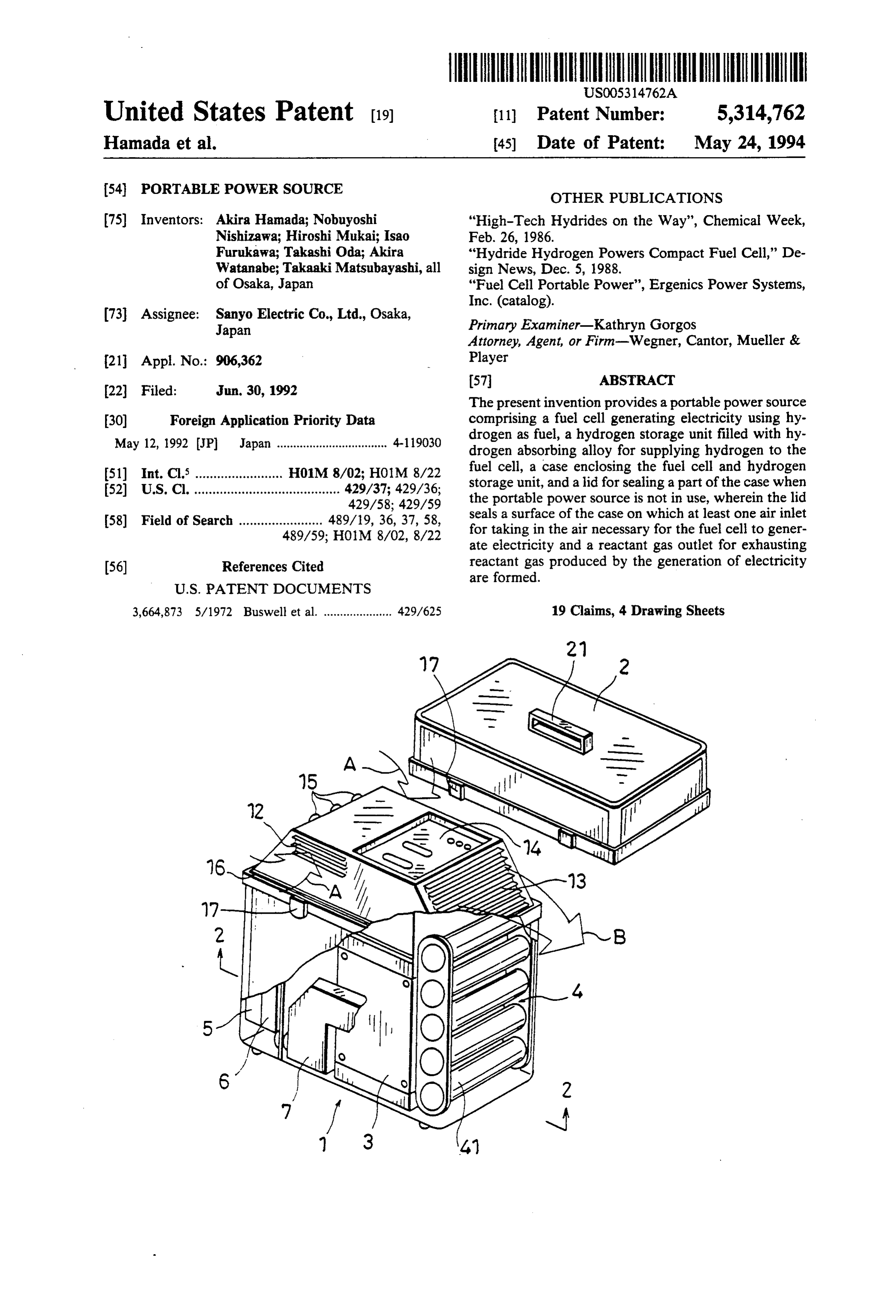
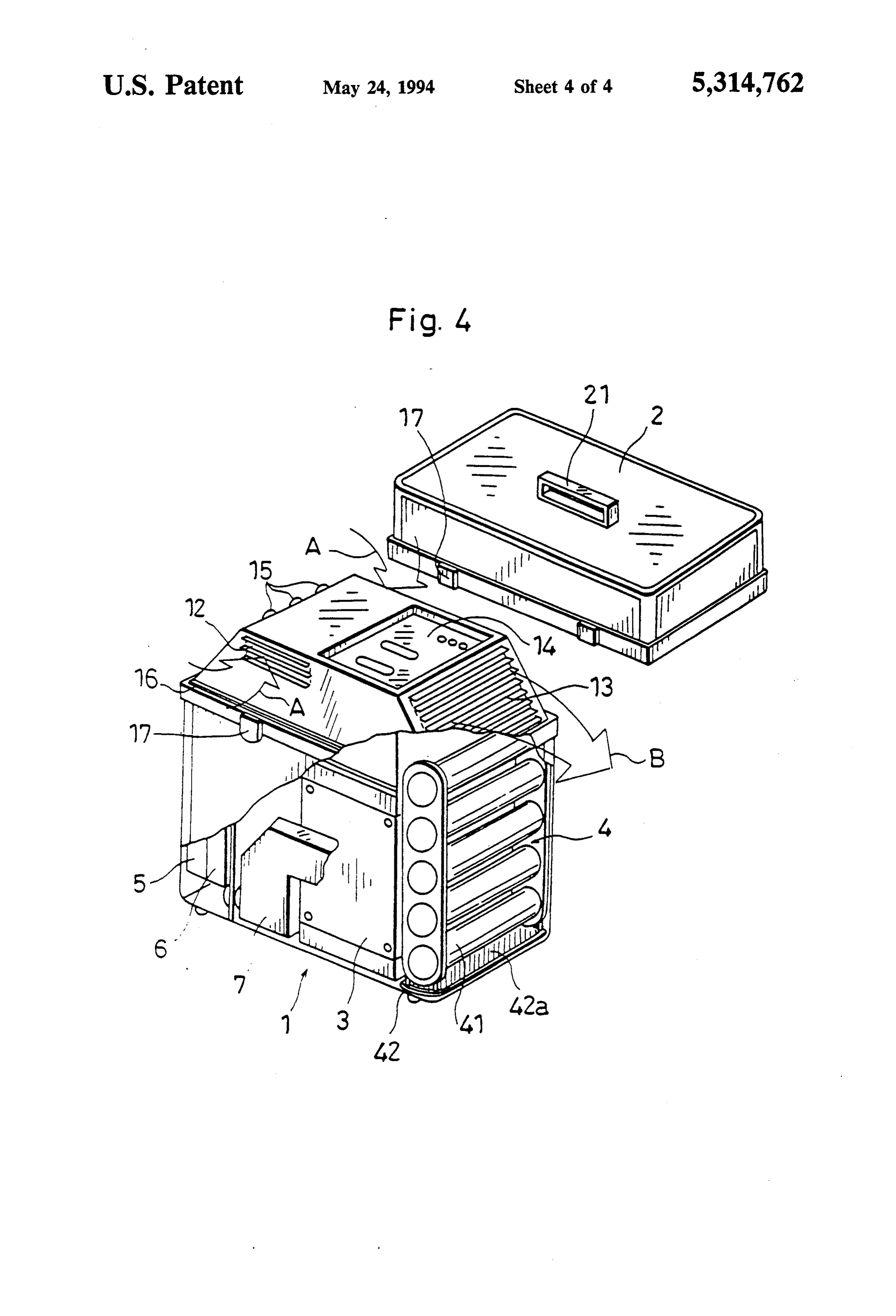
FIG. 1 is of the invention. In the drawings:
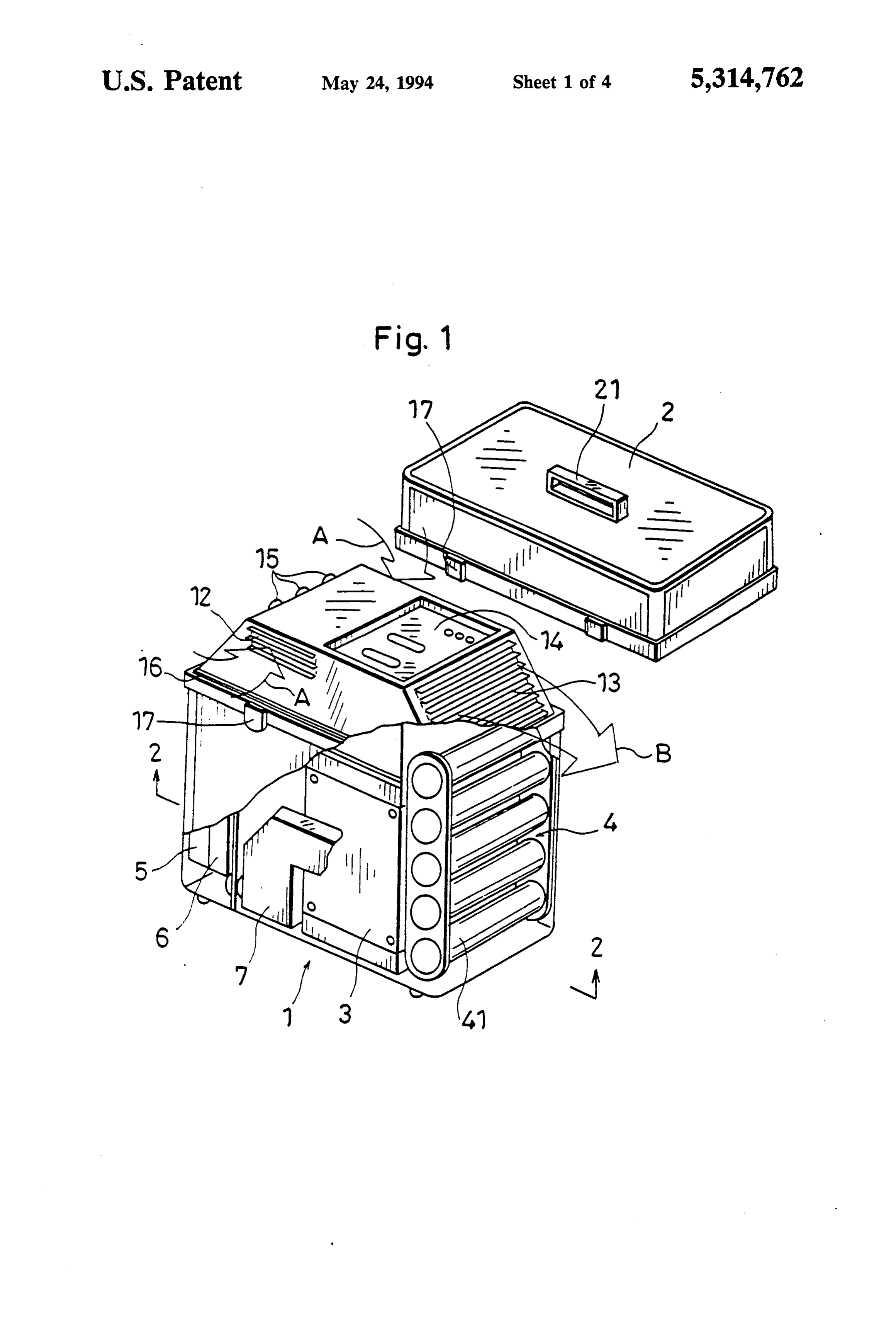
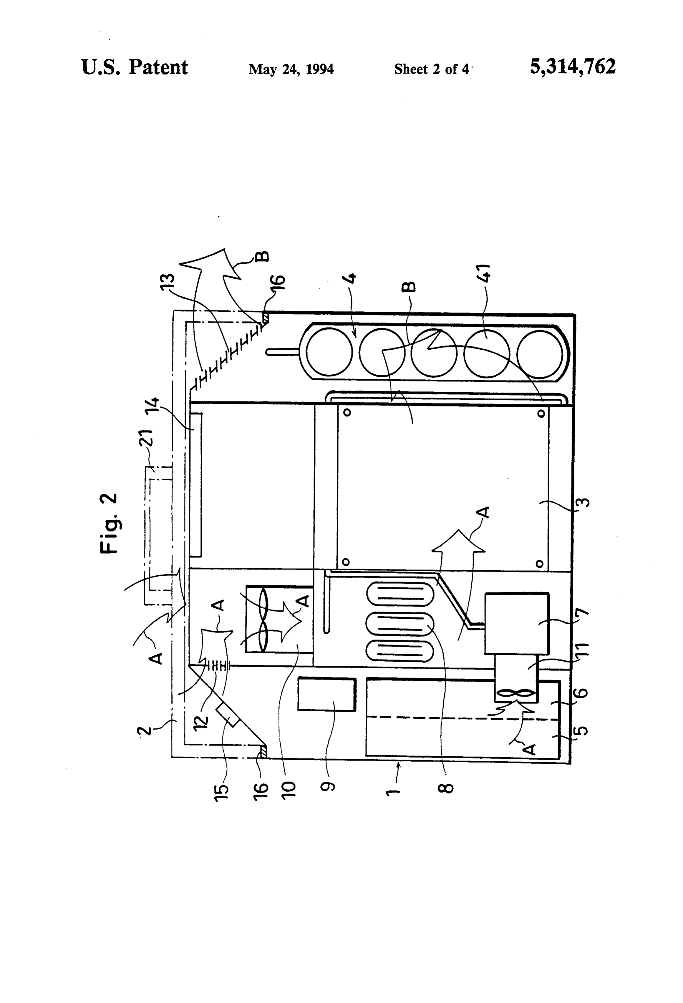
a cross section of the main part of a power a surface of the case on which at least one air inlet for source of the present invention; taking in the air necessary for the fuel cell to generate FIG. 2 is an X-X transverse cross section of FIG. 1; electricity and a reactant gas outlet for exhausting reac FIG. 3 is an enlargement showing a packing of the tant gas produced by the generation of electricity are power source; and formed. 50
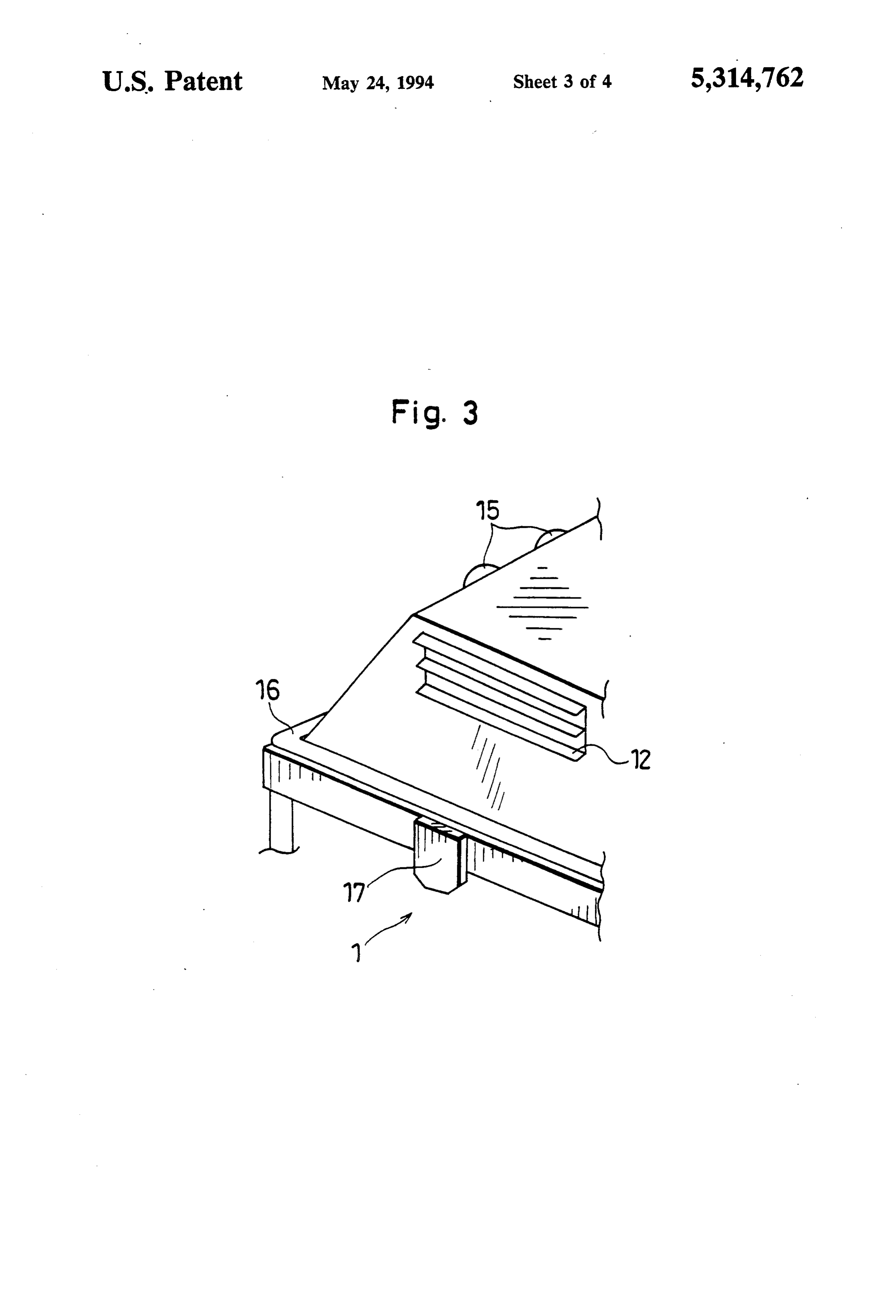
Sealing the air inlet and reactant gas outlet formed on powerF.G. 4 is a cross section of the main part of another the case with the lid prevents the air leakage thereinto source of the present invention. when the portable power source is not in use. There DESCRIPTION OF THE PREFERRED fore, the electrolyte concentration as well as cell char EMBODIMENTS acteristics will not be deteriorated. 55
Embodiment I
The portable power source further comprises an air inlet duct between the air inlet and the fuel cell, and an As shown in FIGS. 1 and 2, the portable power exhaust duct between the fuel cell and the reactant gas source of the present invention comprises a case 1 and a outlet, wherein a part of the internal surface of the case lid 2 made from light metal such as aluminum or DU also serves as a part of the inlet duct and that of the RALUMIN (an aluminum alloy containing copper, exhaust duct. magnesium, and magnanese in a ratio, respectively, of The above construction can reduce parts for the inlet 95:4:0.5:0.5). The case 1 encloses a fuel cell 3 (for in duct and exhaust duct, contributing to the lightening of stance, a phosphoric acid fuel cell), a hydrogen storage the portable power source. unit 4 for supplying hydrogen to the fuel cell 3 during The hydrogen storage unit may be placed in the ex 65 the operation, a control unit 5, a DC-DC converter 6 haust duct. for maintaining constant electromotive force produced Although the temperature of the hydrogen storage by the generation of electricity, a catalytic burner 7 unit falls in the course of the hydrogen supply, the filled with platinum catalyst, a start-up heater 8, a fuse
Page 7
relay box 9, and air supply fans 10 and 11. The hydro to the fuel cell 3. If the temperature of the latter contin gen storage unit 4 includes a number of cylinders filled ues to fall, it becomes incapable of supplying hydrogen, with hydrogen absorbing alloy. The start-up heater 8 bringing deterioration in the generation. However, the and air supply fans 10 and 11 are driven on the electric high-temperature reactant gas transfers the heat of reac ity generated by the fuel cell 3. The start-up heater 8 tion it carries to the hydrogen storage unit 4 while flow heats up the fuel cell 3 to its operation temperature, ing around thereof, thus enabling it to maintain the approximately 100' C. The catalytic burner 7 consumes operatable temperature. On the other hand, although unreacted hydrogen released from the fuel cell 3 with the control unit 5, DC-DC converter 6, and the like are the air from the air supply fan 11 by catalytic combus gradually heated by the radiation from the fuel cell 3, tion so that no unreacted hydrogen will be released to 10 the air from the air inlets 12 cools these devices while the atmosphere. What controls, the portable power flowing around thereof.
source is the control unit 5, and for instance, it controls As a result, smooth and sustainable generation of a rotating speed of the air supply fan 11 in order to electricity is realized with the portable power source. adjust the air supply to the catalytic burner 7, or it controls the operation of the start-up heater 8 like mak 15 andAlthough the air inlets 12, the reactant gas outlet 13 ing it stop heating up the fuel cell 3 at the operation face of the case 1,panel the control they 14 are formed on the upper sur can be formed at any side surface temperature thereof. thereof, provided that the lid 2 covers all of the afore Most of the air taken in from air inlets 12 with the operation of the air supply fan 10 flows directly into the mentioned airtight.
The phosphoric acid fuel cell is used in the embodi fuel cell 3 for the generation of electricity, and the 20 ment, remains flow into the fuel cell 3 after having flown capablehowever, one of the solid oxide fuel cells which is of operating at the lower temperature is also around the control unit 5, DC-DC converter 6, and the applicable.
like so that they cool these devices. The high-tempera ture reactant gas carrying the heat of reaction produced Embodiment II in the fuel cell 3 is released to the atmosphere through 25 As shown in FIG. 4, it has the same construction as a reactant gas outlet 13 while heating up the hydrogen storage unit 4 placed on the way. A part of the internal Embodiment I except that the hydrogen storage unit 4 surface of the case 1 also serves as a part of an air inlet includes a pan 42. Hereinafter, like components are duct between the air inlet 12 and the fuel cell 3 and that labeled with like reference numerals with respect to of an exhaust duct between the fuel cell 3 and the reac 30 Embodiment I, and the description of these components tant gas outlet 13, contributing to lightening of the por is not repeated.
table power source. The hydrogen storage unit 4 having a number of The upper part of the case is a truncated pyramid. cylinders 41 includes the pan 42 at the bottom, which The air inlet 12, another air inlet(not shown), reactant includes an absorber 42a(for instance, Forn 4S, a co gas outlet 13, and connectors 15 are formed on each side 35 polymer of acrylic acid and sodium salt acrylate, surface thereof, respectively, wherein the side surface Sumitomo Seika Chemicals Co., Ltd.). having the air inlet 12 and that having another air inlet As previously mentioned, the temperature of the oppose each other. A control panel 14 is placed on the hydrogen storage unit 4 falls in the course of the hydro top, which includes a lamp indicating a hydrogen re gen supply, and the high-temperature reactant gas from maining pressure, a switch for adjusting the hydrogen the fuel cell 3 helps it to maintain its operatable temper pressure, an switch for opening/shutting a valve when ature, during which the water in the reactant gas con supplying hydrogen or the like(not shown). As shown denses on the surfaces of the cylinders 41 when it in FIG. 3, a packing 16 is placed on the edge of the base touches them. However, substantially all of the conden of the truncated pyramid where the edge of the lid 2 fits sate running down therefrom is collected into the pan so as to encircle the edge, in order to further ensure the 45 42, and further, absorbed into the absorber 42a, making sealing effect. it possible to prevent the electrolyte of the fuel cell 3 The case 1 and lid 2 are sealed together with clamps from absorbing the condensate, therefore, deterioration 17 in a way that the lid 2 covers the truncated pyramid, in cell characteristics.
and with a handle formed on the top of the lid 2, the With the above construction, the condensate is re case, or the portable power source, can be easily carried SO moved easily by taking out the hydrogen storage unit 4 to desired places. from the case 1 in stead of wiping off with a cloth or The operation of the portable power source is de tissue papers.
scribed hereunder with referring to FIGS. 1 and 2, 42a prevents Moreover the the absorption by the absorber condensate from spilling inside the wherein an arrow A indicates the air flow and an arrow
B indicates the reactant gas flow produced by the fuel 55 case 1 even when the portable power source is placed on a tilt. When the absorber 42a has come to its full cell 3 during the generation of electricity.
After the removal of the lid 2, the valve of the hydro capacity;
with a capacity can be easily restored by replacing it new absorber.
gen storage unit 4 is opened by the switch on the con Adding the pan 42 and absorber 42a to the portable trol panel. Then with the remaining(unconsumed) air and hydrogen supplied from the hydrogen storage unit power source does not affect its portability. Table 1 4, the fuel cell 3 pre-generates electricity, which drives shows an operation condition of the portable power the air supply fan 10. With the operation of the air sup source, under which 3 g/min of high-temperature vapor ply fan 10, the air is taken in from the air inlets 12 to the is produced, meaning that less than 3 g/min, or less than fuel cell 3, and the fuel cell 3 accordingly starts the 180 g/hr condensate is produced. Since the capacity of generation of electricity. During the operation, the 65 the absorber 42a is 200 to 600 g/g, only 1 g of the ab temperature of the fuel cell 3 rises by the heat of reac sorber 42a with the volume of 1.05-1.33 ml/g (bulk tion from the generation, while that of the hydrogen density of 0.75-0.95 g/ml) is enough for one hour opera storage unit 4 falls in the course of the hydrogen supply tion of the portable power source.
Page 8
TABLE 1 hydrogen absorbing alloy as well as a pan for collecting DC output capacity (Wh) 250(25OW x 1 hour) condensate running down from the surfaces thereof.
6. A portable power source of claim 5, wherein an
Output voltage (V) 12 absorber is placed on the pan for absorbing the conden Output current (A) 21 sate running down from the surfaces thereof. 7. A portable power source of claim 4, wherein the
It should be noted that the above construction ena hydrogen storage unit includes cylinders filled with bles the portable power source to maintain the portabil hydrogen absorbing alloy as well as the absorber for ity as well as a constant electrolyte concentration by absorbing the condensate running down from the sur preventing the condensate from spilling inside the case 10 faces thereof.
8. A portable power source of claim 1, wherein the 1, therefore deterioration in cell characteristics.
case includes clamps for sealing the case with the lid.
Remarks 9. A portable power source of claim 8, wherein a sealing
The absorber 42a are formed in the pan 42, however, 15 the lid fitsmember is placed on the edge of the case where it can be formed on the hydrogen storage unit 4. therewith so as to encircle the edge. As the absorber 42a, Form 10 SH-NF, Form EP, 10. A portable power source of claim 1 further com prising a catalytic burner for consuming unreacted hy
Form ET (copolymers of acryic acid and sodium salt drogen by combustion.
acrylate, Sumitomo Seika Chemical Co., Ltd.) or the 11. A portable power source comprising: like are also applicable. 20 a case having an internal surface and an upper part The absorber 42a is not a must, however, it is prefera including an upper surface enclosing a fuel cell and ble to have it in order to enhance reliability in prevent a hydrogen storage unit, at least one air inlet and a ing the spill of the condensate inside the case 1. reactant gas outlet formed on the upper surface, Although the present invention has been fully de part of an air inlet duct between the air inlet and the scribed by way of examples with reference to the ac 25 fuel cell and part of an exhaust duct between the companying drawings, it is to be noted that various fuel cell and the reactant gas outlet are formed on changes and modifications will be apparent to those the upper surface, and part of the air inlet duct and skilled in the art. Therefore, unless otherwise such the exhaust duct are formed on the internal surface changes and modifications depart from the scope of the of the case; and present invention, they should be construed as being 30 a lid for sealing the upper part of the case including included therein. the upper surface on which the air inlet and reac What is claimed is: tant gas outlet are formed when the portable power 1. A portable power source comprising: source is not in use.
a fuel cell generating electricity using hydrogen as 35 12. A portable power source of claim 11, wherein the fuel; hydrogen storage unit is placed in the exhaust duct. a hydrogen storage unit filled with hydrogen absorb 13. A portable power source of claim 12, wherein the ing alloy for supplying hydrogen to the fuel cell; lid seals a surface of the case on which a control panel for controlling the operation of the power source is a case having an internal surface enclosing the fuel placed.
cell and hydrogen storage unit; and 14. A portable power source of claim 13, wherein the a lid for sealing a part of the case when the portable hydrogen storage unit includes cylinders filled with power source is not in use, hydrogen absorbing alloy as well as a pan for collecting wherein the lid seals a surface of the case on which at least one air inlet for taking in the air necessary for condensate running down from the surfaces thereof. the fuel cell to generate electricity and a reactant 45 absorber is placedpower 15. A portable on the source of claim 14, wherein an pan for absorbing the conden gas outlet for exhausting reactant gas produced by sate running down from the surfaces thereof. the generation of electricity are formed. 16. A portable power source of claim 15, wherein the 2. A portable power source of claim 1 wherein part of hydrogen storage unit includes cylinders filled with the internal surface of the case forms part of an inlet hydrogen absorbing alloy as well as the absorber for duct between the fuel cell and an air inlet, and part of 50 absorbing the condensate running down from the sur the internal surface forms part of an exhaust duct be faces thereof, tween the fuel cell and a reactant gas outlet. 17. A portable power source of claim 11, wherein the 3. A portable power source of claim 2, wherein the case includes clamps for sealing the case with the lid. hydrogen storage unit is placed in the exhaust duct. 18. A portable power source of claim 17, wherein a 4. A portable power source of claim3, wherein the lid sealing member is placed on the edge of the case where seals a surface of the case on which a control panel for the lid fits therewith so as to encircle the edge. controlling the operation of the power source is placed. 19. A portable power source of claim 11, wherein a 5. A portable power source of claim 4, wherein the handle is formed on theak lid kfor . a carrying
purpose.
hydrogen storage unit includes cylinders filled with
Provenance
- Collection
- Cited prior art
- Original PDF
- patentimages.storage.googleapis.com →
- Filed
- 1992-06-30
- Pages
- 8
- Method
- pdftotext (the PDF's own text layer) + pdftoppm 300dpi page scans
- Source
- Google Patents bibliographic record
- Granted
- 1994-05-24
- Inventors
- Akira Hamada; Nobuyoshi Nishizawa; Hiroshi Mukai; Isao Furukawa; Takashi Oda; Akira Watanabe; Takaaki Matsubayashi; Sanyo Electric Co Ltd
- Transcribed from
- patentimages.storage.googleapis.com →