patent · US4622472
Hybrid electric power generating system
11 November 1986
Page 1 — bibliographic record
United States Patent (19) 11 Patent Number: 4,622,472 Bronicki (45) Date of Patent: Nov. 11, 1986 (54) HYBRD ELECTRIC POWER GENERATING Assistant Examiner-W. E. Duncanson, Jr. SYSTEM Attorney, Agent, or Firm-Sandler & Greenblum (75) Inventor: Lucien Y. Bronicki, Rehovot, Israel (57) ABSTRACT (73) Assignee: Ormat Turbines Ltd., Yavne, Israel A hybrid power system comprises a first energy con verter operating on a closed Rankine cycle and includ (21) Appl. No.: 631,051 ing a vapor generator for vaporizing an organic work 22 Filed: Jul. 16, 1984 ing fluid in response to heat furnished from a heat source associated with a vapor generator, a turbo-gen 51 int.C.' .............................................. FOK 23/04 erator responsive to vaporized working fluid for gener 52) U.S. C. .................................... 290/52; 290/40 F; ating electrical power, and a condenser responsive to 60/655; 60/667 vapor exhausted from the turbo-generator for convert (58) Field of Search ................... 290/4. R, 40 R, 40 C, ing said vapor to a condensed liquid which is returned 290/40 F, 52; 60/695, 660, 664, 667, 706 to the vapor generator. The system also includes a sec 56) References Cited ond energy converter including a thermo-electric gen
erator having a junction, a heat source for heating said junction whereby said thermo-electric generator gener 3,795, 103 3/1974 Anderson .............................. 60/655 ates electrical power, and a heat pipe for conveying 4,104,535 8/1978 Bronicki ................................ 290/52 heat from said last mentioned heat source to the vapor 4,117,344 9/1978 Boerstler et al. ..................... 290/52 generator of the first energy converter and to the junc 4,444,015 4/1984. Matsumoto et al. .................. 60/655 tion.
4,471,622 9/1984 Kuwahara ............................. 60/667
Primary Examiner-William M. Shoop, Jr. 17 Claims, 4 Drawing Figures
Page 2
Drawing sheet — no readable text.
Page 3
Drawing sheet — no readable text.
Page 4
Drawing sheet — no readable text.
Page 5
HYBRD ELECTRC POWER GENERATING a heat source for heating said junction whereby said SYSTEM thermo-electric generator generates electrical power, and a heat pipe for conveying heat from the last men
TECHNICAL FIELD tioned heat source to the vapor generator of the first energy converter and to said junction.
This invention relates to an improved hybrid power According to this aspect of the invention, the thermo generating system of the type described in U.S. Pat. No. electric 4,104,535, the disclosure of which is hereby incorpo electricalgenerator power as provides an alternative source of compared to the turbo-generator of rated by reference.
O the Rankine cycle converter. The thermocouple of the
BACKGROUND ART thermoelectric generator can be heated from a conven tional
U.S. Pat. No. 4,104,535 discloses a hybrid electric ing heat fossil fuel fired source of the type used for provid power generating system having a pair of energy con source to the Rankine cycle converter, or the heat can be a nuclear reactor.
verters each operating on a closed Rankine cycle, each 15 In another aspect of the present invention, a redun energy converter including a vapor generator for va porizing a high molecular weight organic working fluid dant power conversion system is provided comprising a in response to heat furnished from a burner associated plurality of energy converters of the type operating on with the vapor generator. Each converter also includes a closed Rankine cycle utilizing an organic working a hermetically sealed turbo-generator responsive to 20 fluid. Each converter has associated with it a heat varporized working fluid for generating electrical source in the form of a burner, and a selectively opera power, and a condenser responsive to exhaust vapors ble fuel control valve for applying fuel to the burner from the turbo-generator for converting such vapors to which furnishes heat to the vapor generator. In addi a condensed liquid which is returned to the vapor gen tion, an operable nuclear reactor is provided for heating erator completing the working fluid cycle. A sensor, 25 a vapor generator associated with the reactor and va operatively associated with each converter senses the porizing an organic working fluid when the reactor is electrical output of the turbo-generator; and a control operational. A piping arrangement is provided for fur system, responsive to the sensors, controls the burners nishing vaporized working fluid from the vapor genera in the converters so that each converter furnishes about half tor associated with the reactor to each turbo-generator the electrical load on the system in normal opera 30 of the energy converters, tion. and to the vapor generators of One of the converters operates with a working fluid the converters in parallel. Control means are responsive having a higher boiling point than the working fluid in to control signals generated by sensors associated with the other converter; and the condenser of the one con the turbo-generators of each of the converters for con verter rejects heat into the vapor generator of the other trolling operation of the nuclear reactor and the burners converter when the converters are in their normal mode 35 of the converters.
of operation. With this arrangement, the fuel consump A nuclear reactor malfunction sensor is provided for tion of the entire system is about 60% of the fuel con producing a malfunction control signal in response to a sumption of either of the converters when they individ malfunction of the nuclear reactor. The control means ually operate to furnish 100% of the electrical load. is operative, when the reactor is functioning normally, If, during the operation of the converters, a malfunc to effect the transfer of vaporized working fluid from tion occurs in one, the sensor associated with that con the vapor generator associated with the nuclear reactor verter will produce a control signal to which the con trol of the system responds by shutting down the mal to each of the converters, and simultaneously, to pre vent operation of the burners associated therewith. The functioning converter and increasing fuel supply to the 45 control means is also responsive to a malfunction con other converter thus enabling the latter to furnish 100% of the load. The result is a highly-reliable hybrid elec trol signal, which is indicative of the reactor becoming, tric power generating system which finds great applica or remaining non-operational, for causing the burners tion in remotely powered sites associated with pipelines associated with the converters to operate and furnish or transmission line installations. heat to the vapor generators of the respective convert
DESCRIPTION OF THE INVENTION The total rated output of the converters exceeds the normal maximum electrical load on the converters such
The present invention is concerned with improving the reliability by utilizing different energy sources and that provision is made for overload conditions. The different modes for generating electrical power. 55 nuclear reactor is sized to provide sufficient heat for the The improved hybrid power generating system ac simultaneous operation of all the converters at their cording to the present invention includes a first energy rated outputs. If the reactor malfunctions and must be converter operating on a closed Rankine cycle and shut down, the burners associated with the converters including a vapor generator for vaporizing an organic are then made operational and the converters will still working fluid in response to heat furnished from a heat be able to furnish all the electrical load requirements. source associated with the vapor generator, a turbo Finally, an auxiliary converter operating on fossil fuels generator responsive to vaporized working fluid for may also be provided in parallel with the closed Ran generating electrical power, a condenser responsive to kine cycle organic working vapor converters for the vapor exhausted from the turbo-generator for convert purpose of providing power to the load when simulta ing said last mentioned vapor to a condensed liquid, and 65 neous maintenance is required on the organic Rankine means for returning said liquid to the vapor generator. cycle converters and the nuclear reactor. The result is a The system also includes a second energy converter highly-reliable redundant electrical generating power including a thermo-electric generator having a junction, supply system,
Page 6
DESCRIPTION OF DRAWINGS
In the present invention, the heat source for con verter 12A is burner 22 much like burner 14 in con
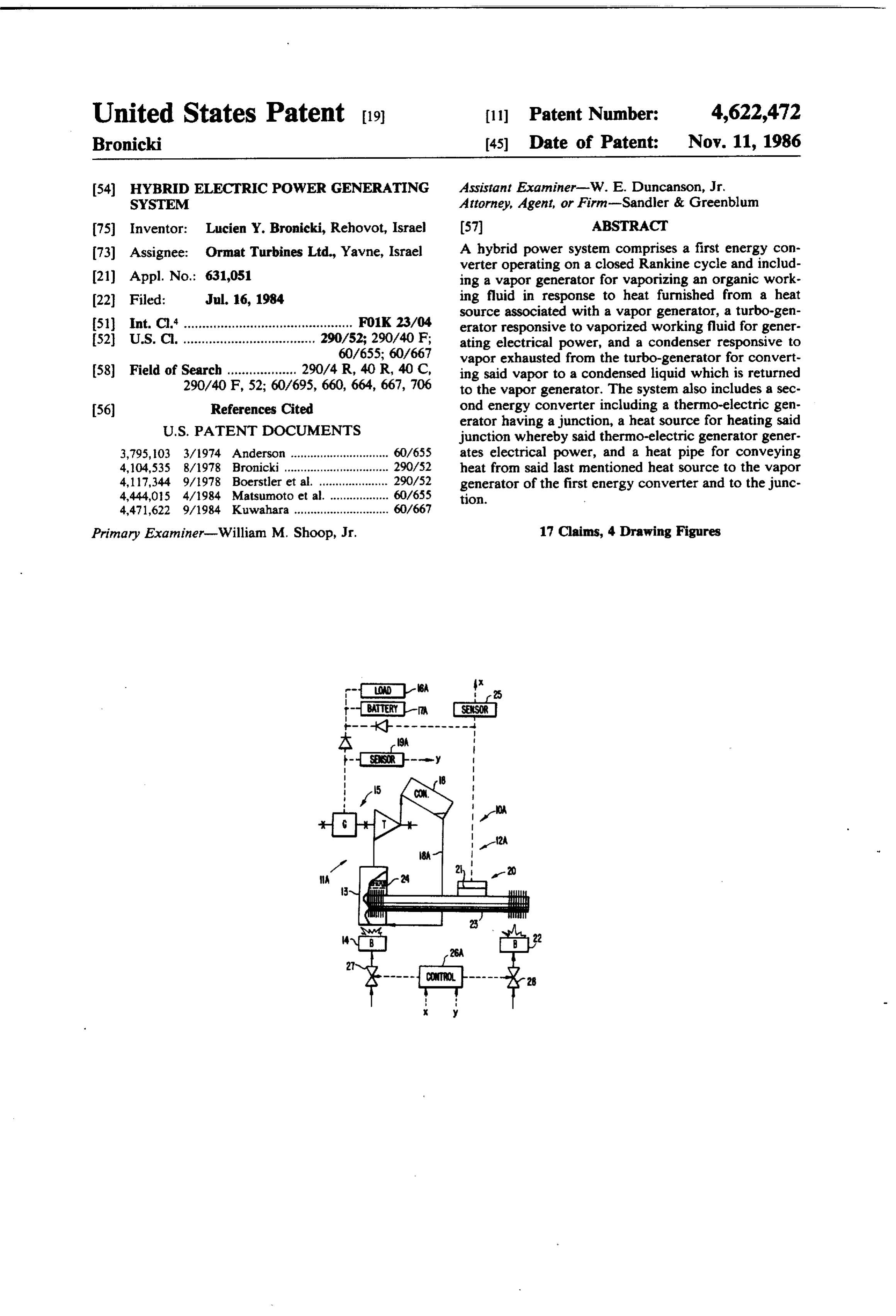
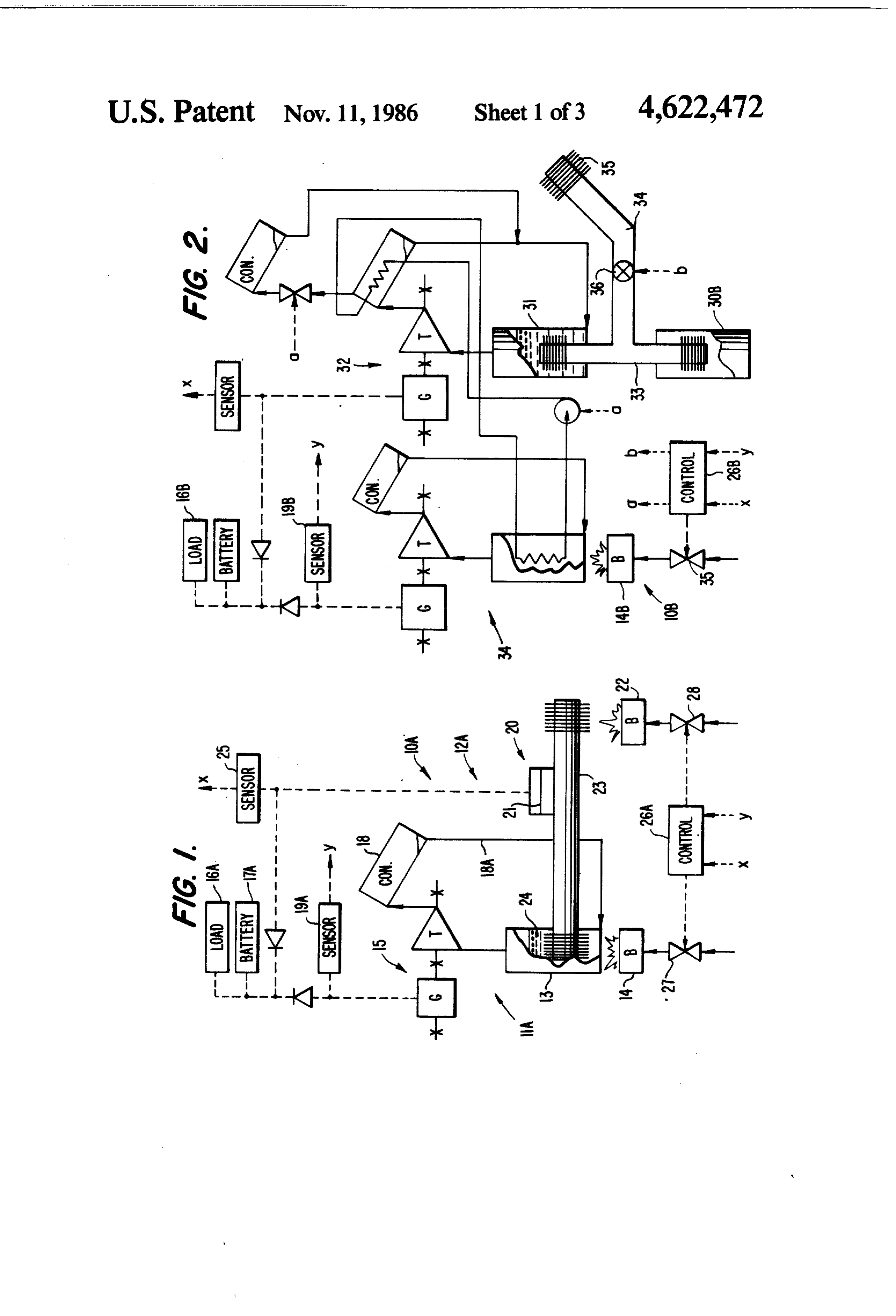
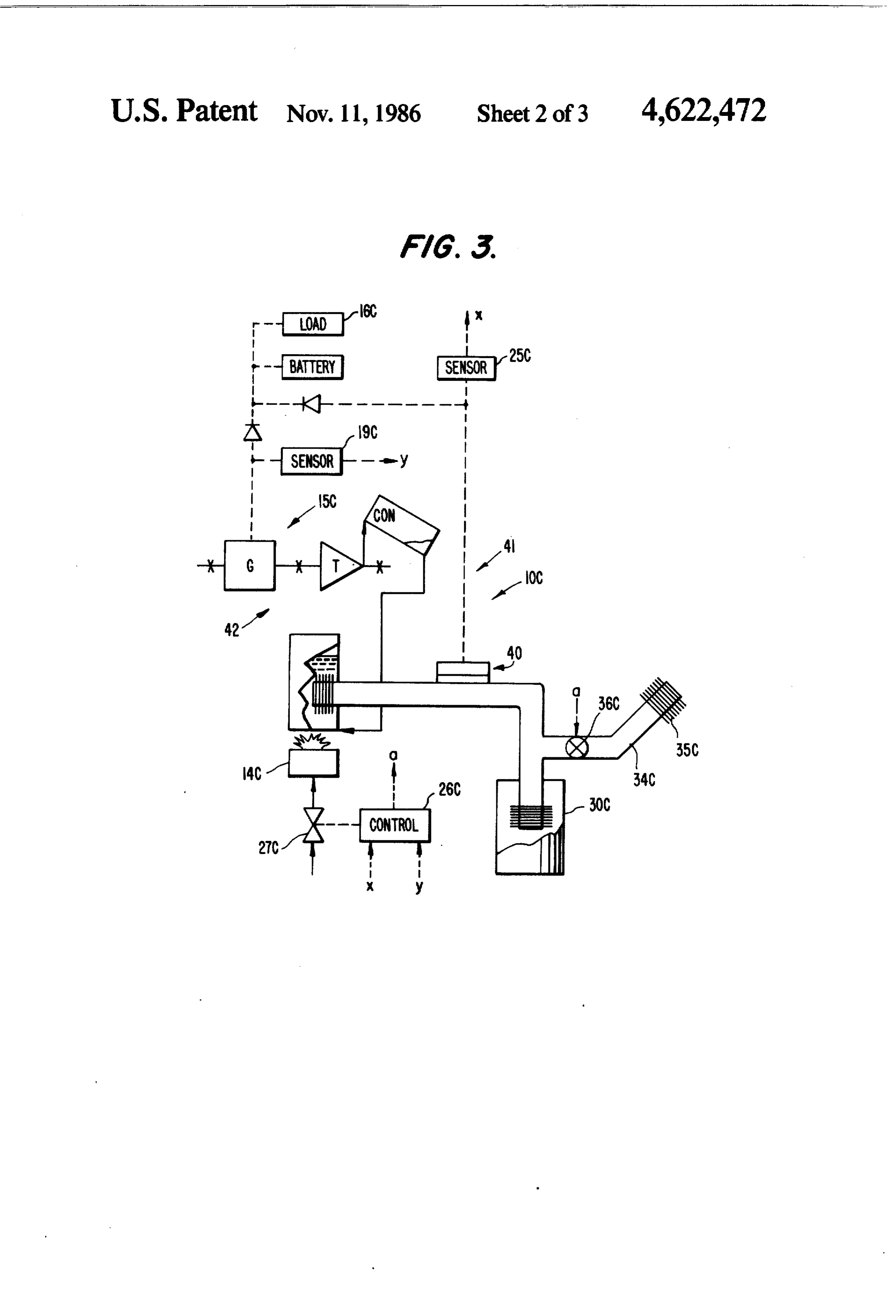
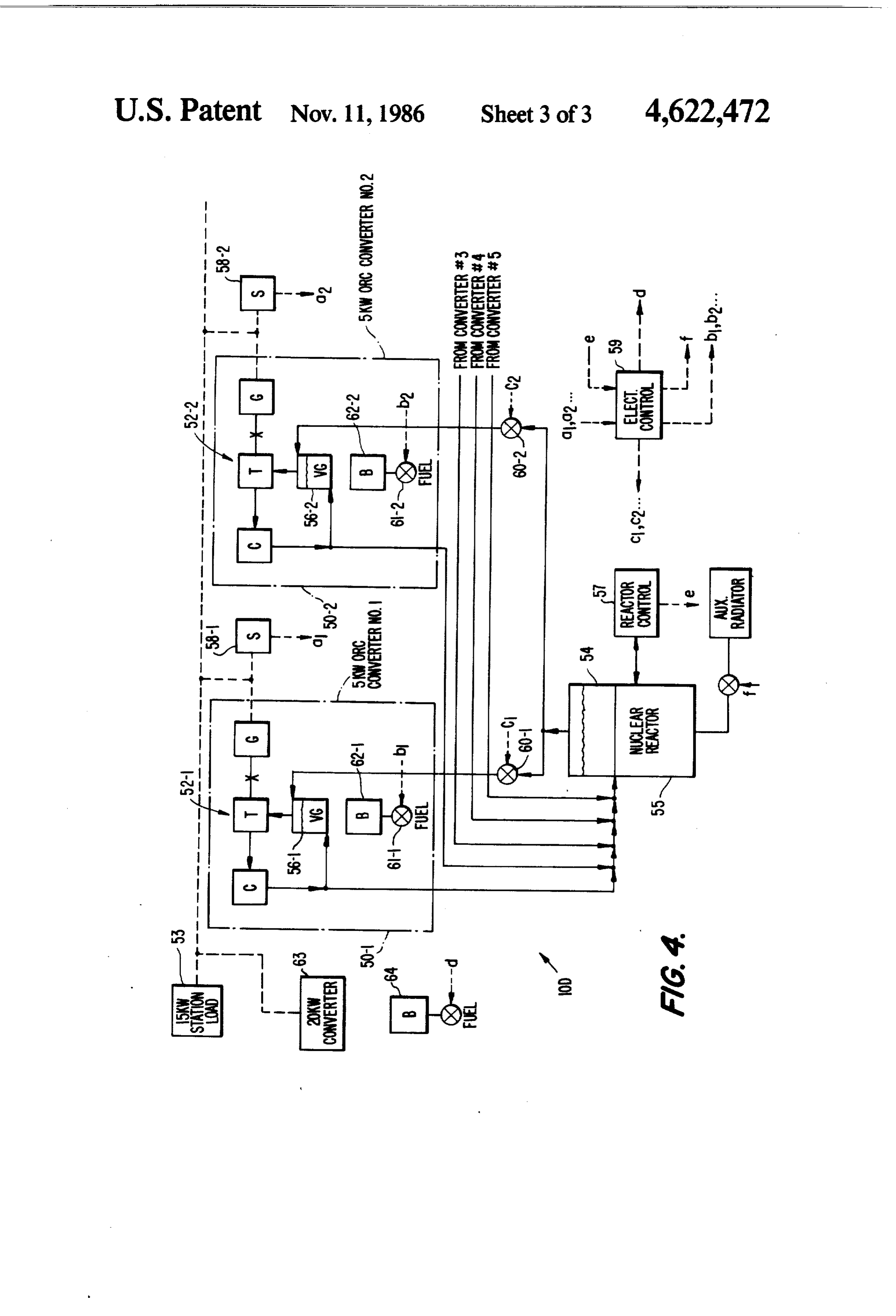
Embodiments of the present invention are disclosed verter 11A. Converter 12A also includes heat pipe 23 by in accompanying drawings wherein: which heat produced by burner 22 is transferred both to FIG. 1 is a block diagram of one embodiment of a 5 junction 21 of the thermo-electric generator and to hybrid electric power generating system according to working fluid 24 contained in vapor generator 13 of the present invention utilizing one organic fluid Ran converter 11A. Finally, sensor 25 associated with con kine cycle converter and a thermo-electric generator, verter 12A monitors the electrical output of the thermo each operating on conventional fossil fuels; electric generator and produces a control signal "x" FIG. 2 is a block diagram of another embodiment of O when the output of the thermoelectric generator de a hybrid electric power generating system similar to creases below a predetermined threshold. that shown in U.S. Pat. No. 4,104,535 but wherein the System 10A also includes control 26A which is capa heat for one of the converters is provided by a nuclear ble of individually operating valves 27, 28 which con reactor; trol the fuel input to each of burners 14 and 22, respec FIG. 3 is a block diagram of a further embodiment of 15 tively,
in response to signals "x' and "y". Thus, control responsive to the absense of control signals from the present invention wherein one of the converters is in the sensors for the the form of a thermo-electric generator, the heat there to the burners to apurpose of adjusting the fuel supply level at which the thermo-electric fore being supplied by a nuclear reactor; and
FIG. 4 is a block diagram of still a further embodi generator of converter 12A and the turbo-generator of ment of the present invention showing a plurality of 20 converter 11A each produce about half of the power organic fluid Rankine cycle converters in which heat is required signal, for load 16A. When one of sensors produces a supplied by either a nuclear reactor or by burners asso control valve of the control 26A responds by closing the converter associated with the sensor that ciated with each of the converters in order to establish produces the control signal cutting the flow of fuel to a highly reliable system. 25 the burner associated therewith, and effectively shut DETALED DESCRIPTION ting down that converter. Simultaneously, control 26A Referring now to FIG. 1 of the drawing, reference to increases the setting of the valve in the other converter 10A designates one embodiment of a hybrid electric its increase the flow of fuel to its burner thus increasing capacity and enabling it to supply the requirements power generating system according to the present in 30 of the load without the assistance of the other converter vention. System 10A comprises two energy converters which has been shut down.
designated by reference 11A and 12A. Energy con Referring now to FIG. 2, a second embodiment des verter 11A is an organic fluid, closed Rankine cycle ignated by reference 10B of the present invention is converter of the type disclosed in U.S. Pat. No. disclosed. This embodiment is similar to the embodi 4,104,535. This converter includes vapor generator 13 35 for vaporizing an organic working fluid in response to ment shown in FIG. 1 of U.S. Pat. No. 4,104,535, except that, in embodiment 10B, the heat for the primary con heat furnished from burner 14 operatively associated verter is supplied by a radio-isotopic heat source such as with the vapor generator. nuclear reactor 30B. Heat from this reactor is trans Turbo-generator 15 is responsive to vaporized work ferred to vapor generator 31 of primary converter 32 by ing fluid produced by vapor generator 13 for generating means of heat pipe 33. Heat pipe 33 includes bypass heat electric power which is supplied to load 16A. Battery pipe 34 having radiator 35 for transferring heat to an backup 17A insures emergency back-up power for the ambient sink such as the atmosphere in order to provide load upon catastrophic failure. Finally, condenser 18 of emergency cooling for the reactor. Selectively operable converter 11A is responsive to vapor exhausted from heat flow controller 36 is interposed between nuclear turbo-generator 15 for converting the vapor to con 45 reactor 30B and vapor generator 31 of the primary densed liquid which is returned by conduit 18A to the converter. This controller has a first state in which heat vapor generator thus completing the organic working from the reactor is conducted to radiator 35 by way of fluid cycle. Preferably, the elevation of the condenser bypass 34, and a second state in which heat from the with respect to the vapor generator is selected such that reactor is blocked with respect to bypass 34. Control the hydrostatic head on the condensed liquid is ade 50 signal "b' applied to the heat flow controller 36 estab quate to permit it to enter the vapor generator. lishes the state thereof. Otherwise, the operation of the Converter 11A also includes sensor 19A for generat device shown in FIG. 2 is the same as the operation ing a control signal designated "y" when the electric shown in the device of FIG. 1 of U.S. Pat. No. power generated by turbo-generator 15 decreases 4,104,535.
below a predetermined threshold. Thus, sensor 19A 55 In general, both converters in embodiment 10B oper produces a control signal when the output of converter ate at half power supplying load 16B. If reactor 30B 11A begins to drop due to a malfunction in the con malfunctions, the malfunctioning is sensed by control verter, or in burner 14. 26B thereby shutting down the reactor, or establishing Converter 12A comprises thermo-electric generator the state of controller 36, but also opening valve 358 20, which is a conventional device that converts heat 60 associated with burner 14B of secondary converter 34B directly into electricity using the Seebeck effect. In enabling the turbo-generator thereof to furnish all of the such a device, two different conductors are joined in a power to load 16B. Alternatively, a malfunction in con loop, and by establishing a temperature differential verter 34B is sensed by the output of sensor 19B causing across the junction 21 between the conductors, a gener controller 26B to interrupt the flow of fuel to burner ated voltage is produced. Conventional thermo-electric 65 14B thereby shutting down converter 34B while at the generators are available in sizes exceeding 5 KW with same time enabling more heat from nuclear reactor 30B primary energy sources being hydrocarbon fuels, radio to be applied to vapor generator 31. In such case, con isotopes, as well as solar energy. verter 32 would supply the entire load.
Page 7
Embodiment 10C is similar to embodiment 10A ex malfunctioned is deprived of further vapor thus shut cept that the heat source for thermo-electric generator ting down the operation of that converter while addi 40 of converter 41 is a radioisotopic heat source such as tional vapor is furnished to the remaining operational nuclear reactor 300 which is similar to nuclear reactor converters. Thus, the level of operation of the remain 30 shown in FIG. 2. In operation, thermo-electric gen ing converters increases from about 60% to about 80% erator 40 and turbo-generator 15C of converter 42 each which is adequate to supply normal station loads with a furnish half of the power to load 16C. If a malfunction reserve for abnormal conditions. were to occur in nuclear reactor 30C, such malfunction In the event of a malfunction in the nuclear reactor, would be sensed by sensor 25C whose control signal this condition is sensed by reactor control 57 and con "x' is applied to control 26C. The control responds by 10 veyed to control 59 for the purpose of operating valves shutting down the reactor, and/or establishing the state 61-1, 61-2, etc., associated with burners 62-1, 62-2, etc., of controller 36C such that bypass heat pipe 34C would of the converters. In such case, these burners begin to transmit heat to radiator 35C. Simultaneously, valve supply heat to vapor generators 56-1, 56-2, etc., of the 27C would be opened by the control allowing burner converters for enabling them to supply vaporized work 14C to receive additional fuel thereby enabling the 15 ing fluid to the respective turbo-generators of the con turbo-generator 15C to supply all of the load require verters without interrupting the supply of power to ments. Alternatively, malfunction in converter 42C load 53. Again, if a turbo-generator in one of the con would be sensed by output of sensor 19C such that the verters malfunctions, control 59 is effected to shut controls of reactor 30C would be modified to enable the down the fuel supply of that converter and increase the reactor to operte at a higher level and thus enable ther 20 fuel supply to the other converters enabling them to mo-electric generator 40 to supply all the power to load take up the entire load for the station. 16C. Finally, a backup converter 63 may also be provided Embodiment 10D shown in FIG. 4 is a redundant of a capacity equal to the rated capacity of each of power conversion system comprising a plurality of individual converters 50-1, 50-2, etc. Heat to converter energy converters each operating on closed Rankine 25 63 is furnished cycle similar to converters 11A and 42 in embodiment cal control 59. by burner 64 under the control of electri Converter 63 is provided to permit main 10A and 10C, respectively. That is to say, embodiment 10D has a plurality of substantial identical energy con tenance of the main converters 50-1, 50-2, etc. It is believed that the advantages and improved re verters designated by reference numerals 50-1,50-2, etc. sults furnished by the method and apparatus of the pres Each converter includes a turbo-generator 52-1, 52-2, 30 ent invention are apparent from the foregoing descrip etc., to which vaporized organic working fluid is sup plied enabling the generator of the turbo-generator to tion of the preferred embodiment of the invention. Vari supply an equal fraction of the total station load 53. The ous changes and modifications may be made without vaporized working fluid is normally obtained from departing described from the spirit and scope of the invention as in the claims that follow.
vapor generator 54 to which heat is supplied by nuclear 35
I claim:
reactor 55. Vapor exhausted from each turbine of the 1. A hybrid power system comprising: turbo-generators of the converters is condensed in indi vidual condensers located in the converters or associ (a) a first energy converter operating on a closed ated with the converters and the condensed working Rankine cycle and including a vapor generator for fluid is returned to vaporizer 54. Thus, vapor generator 40 vaporizing an organic working fluid in response to 54 supplies all of the turbines in parallel with vporized heat furnished from a heat source associated with working fluid in parallel from vapor generator 54. Pref. the vapor generator, a turbo-generator responsive erably, the vapor is applied to the turbines through to vaporized working fluid for generating electri vapor generators 56-1, 56-2, etc., respectively, associ cal power, a condenser responsive to vapor ex ated with the converters. 45 hausted from the turbo-generator for converting In the example shown in FIG. 4, five converters are such vapor to a condensed liquid, and means for provided, each having a capacity of 5 KW while the returning said liquid to the vapor generator; station load is less than that, say 15 KW. The controls of (b) a second energy converter including a thermo the system are establishedsuch that each converter op electric generator having a junction, a heat source erates just under its rated capacity for furnishing an 50 for heating said junction whereby such thermo equal amount of power to the station load. Thus, each electric generator generates electrical power; converter operates at about 60% of its rated capacity (c) a heat pipe for conveying heat from the heat under normal conditions. source of said second converter to the vapor gener When the station load increases, the level of opera ator of said first converter and to said junction; and tion of each of the converters is increased by control 55 (d) means for applying the electrical power generated ling the amount of vapor furnished to the converters in by said first and second converters to an electrical parallel. This is achieved by reactor control 57 which load.
senses the station load. 2. A hybrid power system according to claim 1 in The output of the turbo-generator associated with cluding a sensor individually associated with each con each converter is individually sensed by sensors 58-1, verter for generating a control signal when electrical 58-2, etc. In the event that one of the turbo-generators, power generated by the converter associated with the or one of the converters malfunctions, the malfunction sensor decreases below a threshold, and control means is sensed by the sensor which produces a control signal responsive to control signals generated by the sensors that is applied to electrical control 59. In response, for controlling the operation of the heat sources of the electrical control 59 produces signals that adjust flow 65 coveters.
control valves 60-1, 60-2, etc., by which vapor is fur 3. A hybrid power system according to claim 2 nished from vapor generator 54 to individual ones of the wherein the heat source of the first converter is a burner converters. The converter whose turbo-generator has that burns fossil fuel.
Page 8
4. A hybrid power system according to claim 3 12. A hybrid power system according to claim 11 wherein said control means is responsive to a control wherein said means for rejecting heat is associated with signal generated by the sensor of the first converter for the condenser of said one converter. cutting off the flow of fuel to the burner thereof. 13. A hybrid power system according to claim 12 5. The hybrid power system according to claim 4 including a heat pipe for transferring heat between said wherein said control means is responsive to a control radioactive heat source and the vapor generator of said signal generated by the sensor of the first converter for one converter, a bypass heat pipe having radiator means increasing the heat produced by the heat source in the for transferring heat to an ambient sink, and a selec second converter.
tively operable heat-flow controller interposed between
O said reactor and the vapor generator of the first con 6. A hybrid power system according to claim 2 verter, said controller having a first state in which heat wherein the heat source of each converter is a burner from said reactor is conducted to said radiator means of that burns fossil fuel, and said control means is respon said bypass, and second state in which heat from said sive to a control signal generated by a sensor from one reactor is blocked with respect to said bypass. of the converters for cutting off the flow of fuel to the 5 14. A hybrid power system according to claim 13 burner of said one converter, and to increase the flow of including a reactor level sensor for sensing the reactor fuel to the burner of the other converter. level in said reactor and producing a control signal 7. A hybrid power system according to claim 5 when said level increases both threshold, and said heat wherein the heat source of the second converter is a flow controller being responsive to a control signal said radioisotopic heat source. 20 reactor level sensor for causing the state of said control 8. A hybrid power system according to claim 7 ler15. to change to and remain in said first state. wherein said heat pipe includes a bypass heat pipe hav Ing: A redundant power conversion system compris ing radiator means for transferring heat to an ambient (a) a plurality of energy converters each of which sink; and a selectively operable heat-flow controller 25 operates on a closed Rankine cycle and each of interposed between said radioisotopic source and the which includes a vapor generator for vaporizing an vapor generator of said first converter, said controller organic working fluid in response to heat furnished having a first state in which heat from said radioisotopic from a heat source associated with a vopor genera source is conducted to said radiator means of said by tor, a turbo-generator responsive to vaporized pass, and a second state in which heat from said radio working fluid for generating electrical power, and isotopic source is blocked with respect to said bypass. 30 a condenser responsive to vapor exhausted from 9. A hybrid power system according to claim 8 in the turbo-generator for converting such vapor to a cluding a reactor level sensor for sensing the reactor condensed liquid, and means for returning said level in said radioisotopic heat source and producing a liquid to the vapor generator, and a sensor for control signal when said level increases or decreases 35 generating a control signal when the electrical with respect to a threshold, said heat flow controller power generated by the converter decreases below been responsive to a control signal from said reactor a threshold;
level sensor for causing the state of said control to (b) each converter having a heat source in a form of a burner, and a selectively operable fuel control change and to remain in a new state. valve for applying fuel to the burner which fur 10. A hybrid power system comprising: nishes heat to the vapor generator; (a) at least two energy converters, each operating in (c) an operable nuclear reactor; a closed Rankine cycle and each including a vapor (d) a vapor generator associated with the nuclear generator for vaporizing an organic working fuid reactor for vaporizing an organic working fluid in response to heat furnished from a heat source when said nuclear reactor is operating; associated with the vapor generator, a turbo-gener 45 (e) means for selectively furnishing vaporized work ator responsive to vaporized working fluid for ing fluid from the vapor generator associated with generating electrical power, a condenser respon the nuclear reactor to each turbo-generator of said sive to vapor exhausted from the turbo-generator energy converter; and for converting such vapor to a condensed liquid, 50 (f) control means responsive to control signals gener and means for returning said liquid to the vapor ated by said sensors for controlling the operation of generator; said nuclear reactor and the burners of said con (b) the heat source for one of the converters including verters.
a nuclear reactor, and the heat source of the other 16. A redundant power conversion system according of the converters been a burner that burns fossil 55 to claim 15 including a nuclear reactor malfunction fuel; sensor for producing a malfunction control signal in response to a malfunction of the nuclear reactor, said (c) a sensor individually associated with each con control verter for generating a control signal when electri functionmeans been responsive to the absence of a mal cal power generated by the converter associated porized working signal control for effecting the transfer of va fluid from the vapor generator associ with the sensor decreases below a threshold; and 60 ated with the nuclear reactor and preventing operation (d) control means responsive to control signals gener of the burner of each converter, and being responsive to ated by the sensors for controlling the operation of the presence of a malfunction control signal for causing the heat source of the converters, said burners to operate and furnish heat to the vapor 11. A hybrid power system according to claim 10 generator of the respective converters.
including means for rejecting heat from the condenser 65 17. A redundant power conversion system according of said one converter into the vapor generator of said to claim 16 wherein the total rated capacity of the con other converter only in the absence of the control signal verters exceeds the normal
load ons the system.
from the sensor associated with said other converter.
Page 9
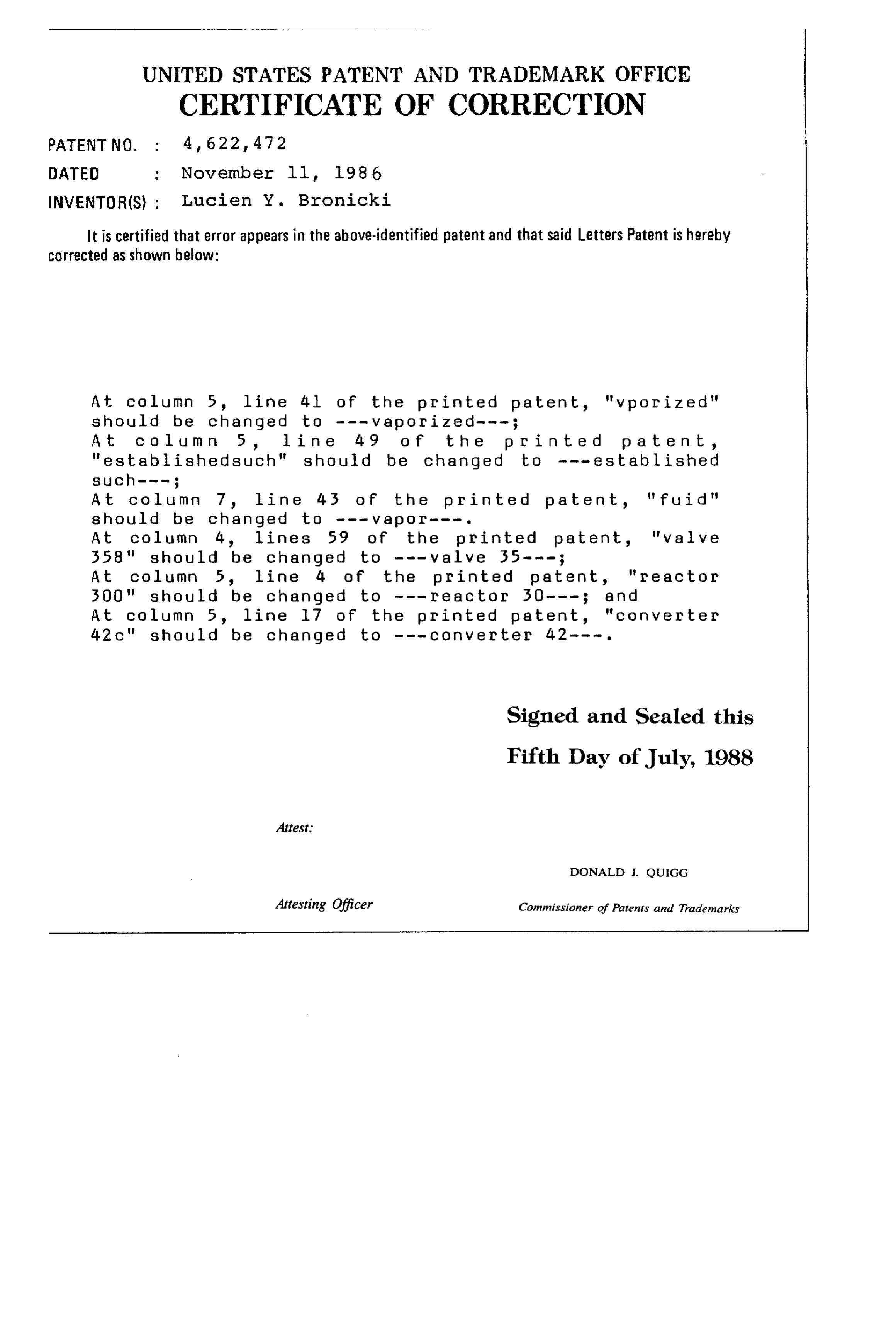
UNITED STATES PATENT AND TRADEMARK OFFICE
CERTIFICATE OF CORRECTION
DATED : November ll, l986
INVENTOR(S) ; Lucien Y. Bronicki
It is certified that error appears in the above-identified patent and that said Letters Patent is hereby Corrected as shown below:
At Column 5, line 4l of the printed patent, "w porized" should be changed to - - - vaporized- - - ; At column 5, line 49 of the p r in t e d p a ten t , "established such" should be changed to - - - established
At Column 7, line 43 of the printed patent, "fluid" should be changed to - - - vapor ---.
At column 4, lines 59 of the printed patent, "valve
At column 5, line 4 of the printed patent, "re actor 500" should be changed to --- reactor 50--- ; and At Column 5, line l7 of the printed patent, "converter 42 C" should be changed to --- converter 42---.
Signed and Sealed this
Fifth Day of July, 1988
Attest:
DONALD J. QUIGG
Attesting Officer Commissioner of Parents and Trademarks
Provenance
- Collection
- Cited prior art
- Original PDF
- patentimages.storage.googleapis.com →
- Filed
- 1984-07-16
- Pages
- 9
- Method
- pdftotext (the PDF's own text layer) + pdftoppm 300dpi page scans
- Source
- Google Patents bibliographic record
- Granted
- 1986-11-11
- Inventors
- Lucien Y. Bronicki; Ormat Turbines Ltd
- Transcribed from
- patentimages.storage.googleapis.com →