patent · US5514486
Annular feed air breathing fuel cell stack
7 May 1996
Page 1 — bibliographic record
United States Patent (19) 11 Patent Number: 5,514,486 Wilson 45 Date of Patent: May 7, 1996 54). ANNULAR FEED AIR BREATHING FUEL K. Prater "Solid polymer fuel cell developments at Ballard', CELL STACK Journal of Power Sourcer, 37, 181-188 (1992) month not avail.
(75) Inventor: Mahlon S. Wilson, Los Alamos, N.M.
73) Assignee: The Regents of the University of Primary Examiner-Anthony Skapars California, Office of Technology Attorney, Agent, or Firm-Ray G. Wilson
Transfer, Alameda, Calif.
22 Filed: Sep. 1, 1995 A stack of polymer electrolyte fuel cells is formed from a plurality of unit cells where each unit cell includes fuel cell (51) Int. Cl. ........................................... HOM 8/10 components defining a periphery and distributed along a 52 U.S. Cl. .................................. 429/30, 429/31; 429/34 common axis, where the fuel cell components include a 58 Field of Search .................................. 429/30, 31, 33, polymer electrolyte membrane, an anode and a cathode 429/32, 34, 38, 39 contacting opposite sides of the membrane, and fuel and oxygen flow fields contacting the anode and the cathode, 56) References Cited respectively, wherein the components define an annular region therethrough along the axis. A fuel distribution mani
4,824,742 4/1989 Parry ......................................... 429/30 the fuel flow field in each of the unit cells. In a particular 5,158,837 10/1992 Misawa et al. . ... 429/34 embodiment, a single bolt through the annular region clamps 5,176,967 1/1993 Ishihara et al. . ... 429/31 the unit cells together. In another embodiment, separator 5,185,219 2/1993 Ishihara et al. ........................... 429/31 plates between individual unit cells have an extended radial 5,186,806 2/1993 Clark et al. ........................... 429/30 X dimension to function as cooling fins for maintaining the OTHER PUBLICATIONS operating temperature of the fuel cell stack.
Neutzler et al., Development of a Portable Air-Breathing
Polymer Electrolyte Fuel Cell Stack, Extended Abstracts vol. 94-2, p. 961, Oct. 1994. 10 Claims, 5 Drawing Sheets
Page 2
Drawing sheet — no readable text.
Page 3
Drawing sheet — no readable text.
Page 4
Drawing sheet — no readable text.
Page 5
Drawing sheet — no readable text.
Page 6
Drawing sheet — no readable text.
Page 7
ANNULAR FEED AR BREATHING FUEL It is another object of the present invention to minimize CELL STACK water loss and drying of the cell.
Yet another object of the present invention is to minimize over-heating of the cell.
BACKGROUND OF THE INVENTION One other object of the present invention is to provide a This invention relates to polymer electrolyte fuel cells, PEFC stack with a simple geometry and of minimum size and, more, particularly to air-breathing polymer electrolyte and weight.
fuel cells. This invention was made with government sup Additional objects, advantages and novel features of the port under Contract No. W-7405-ENG-36 awarded by the 10 invention will be set forth in part in the description which U.S. Department of Energy. The government has certain follows, and in part will become apparent to those skilled in rights in the invention. the art upon examination of the following or may be learned Fuel cell systems developed to date have generally been by practice of the invention. The objects and advantages of relatively high power, sophisticated and costly systems the invention may be realized and attained by means of the intended for space and transportation applications. These 15 instrumentalities in the appended and combinations particularly pointed out claims.
systems require a number of subsystems to serve such needs as cooling, humidification/water management, and reactant SUMMARY OF THE INVENTION pressurization, all of which must be integrated with one another to attain optimal performance from the assembled To achieve the foregoing and other objects, and in accor fuel cell stack. 20 dance with the purposes of the present invention, as embod An emerging class of polymer electrolyte fuel cells ied and broadly described herein, the apparatus of this (PEFCs) is designed for low power applications, such as invention may comprise a polymer electrolyte fuel cell now served by conventional batteries. The PEFC has attrac where the fuel cell components define a periphery and are tive features of energy density and ease of refueling that distributed along a common axis. The fuel cell components make the PEFC attractive for a number of such applications. 25 include cathode a polymer electrolyte membrane, an anode and a contacting opposite sides of the membrane, and fuel
But a relatively low-cost, unsophisticated fuel cell is needed that is not humidified, cooled, or pressurized. In a simple respectively,flow and oxygen fields contacting the anode and the cathode, wherein the components define an annular embodiment, air (oxygen) is supplied to a cathode by region therethrough along the axis. A fuel distribution mani diffusion from the fuel cell periphery so that there is no requirement for forced convection through the flow-field to 30 fold within the annular region is connected to deliver fuel to the fuel flow field.
replenish the depleted oxygen. That is, the fuel cell stack is "air-breathing.” In another aspect of the present invention, a stack of It will be appreciated that such simple fuel cell stacks are unit cells electrolyte polymer where each fuel cells is formed from a plurality of unit cell includes fuel cell components useful in a number of military, commercial, and consumer 35 defining a periphery and distributed along a common axis, applications. The specific energy of the system can be where the fuel cell components include a polymer electro tailored for a particular device with the appropriate choice lyte membrane, an anode and a cathode contacting opposite and size of hydrogen storage medium. For example, some sides of the membrane, and fuel and oxygen flow fields applications might desire the simplicity and relatively high energy density of pressurized hydrogen storage. On the other 40 contacting the components the anode and the cathode, respectively, wherein define an annular region therethrough along hand, concerns for consumer safety can be met with the use the axis. A fuel distribution manifold within the annular of a metal hydride container for the storage of the hydrogen region is connected to deliver fuel to the fuel flow field in fuel. each of the unit cells.
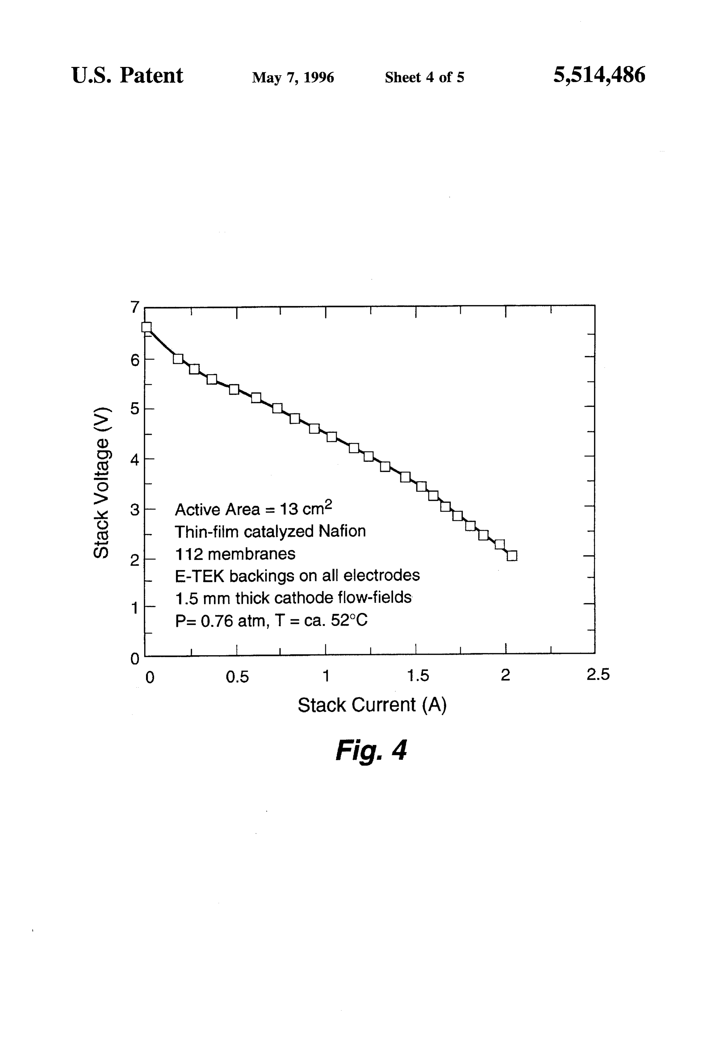
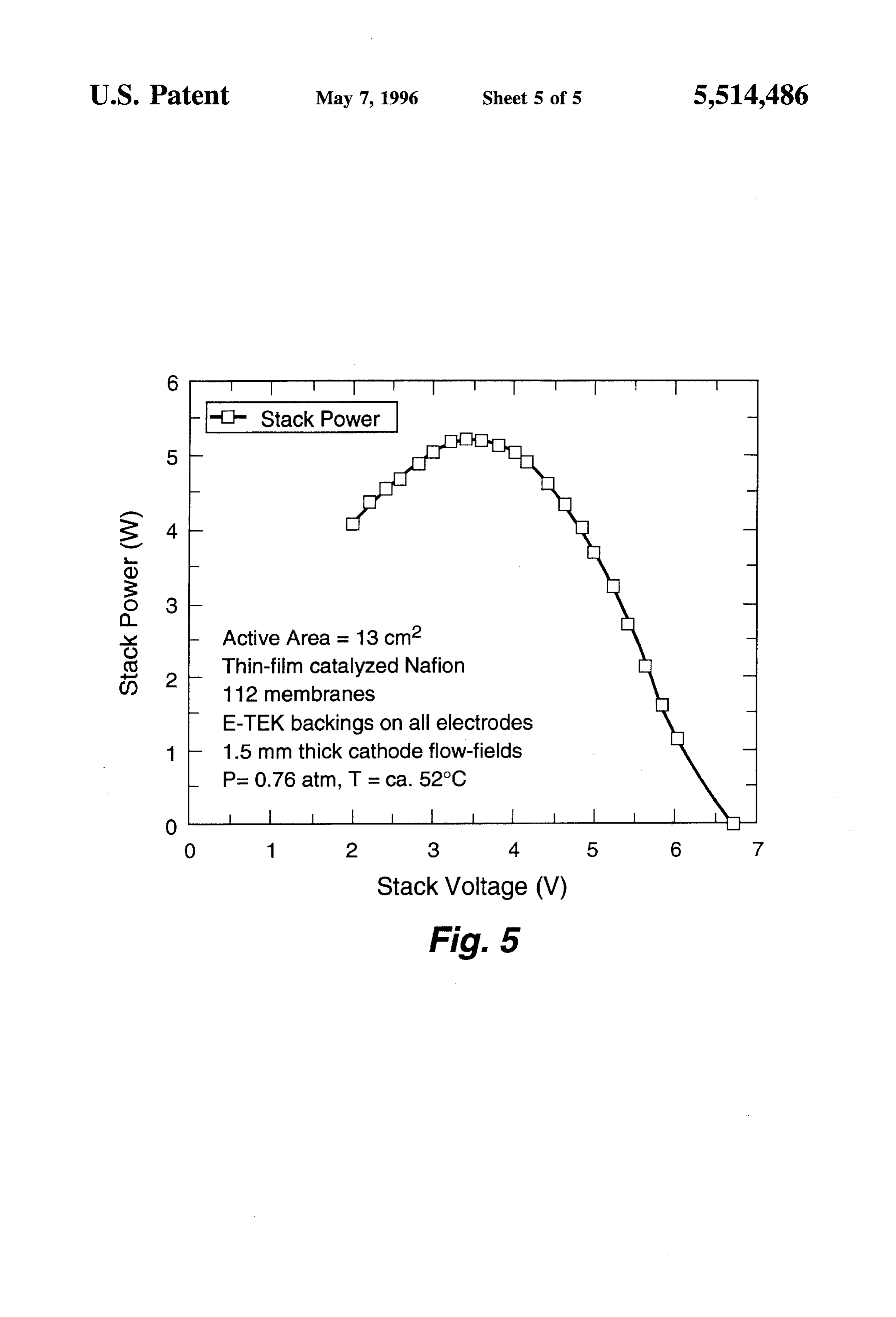
An appropriate fuel cell for these types of applications is BRIEF DESCRIPTION OF THE DRAWINGS the PEFC. When compared to other types of fuel cells such 45 as phosphoric acid, molten carbonate, or solid oxide, the The accompanying drawings, which are incorporated in PEFC possesses substantial advantages because of its com and form a part of the specification, illustrate the embodi bination of low temperature operation, ability to start-up ments of the present invention and, together with the quickly, simplicity, and benign electrolyte. description, serve to explain the principles of the invention. Air-breathing fuel cell stacks designed to-date are smaller 50 In the drawings:
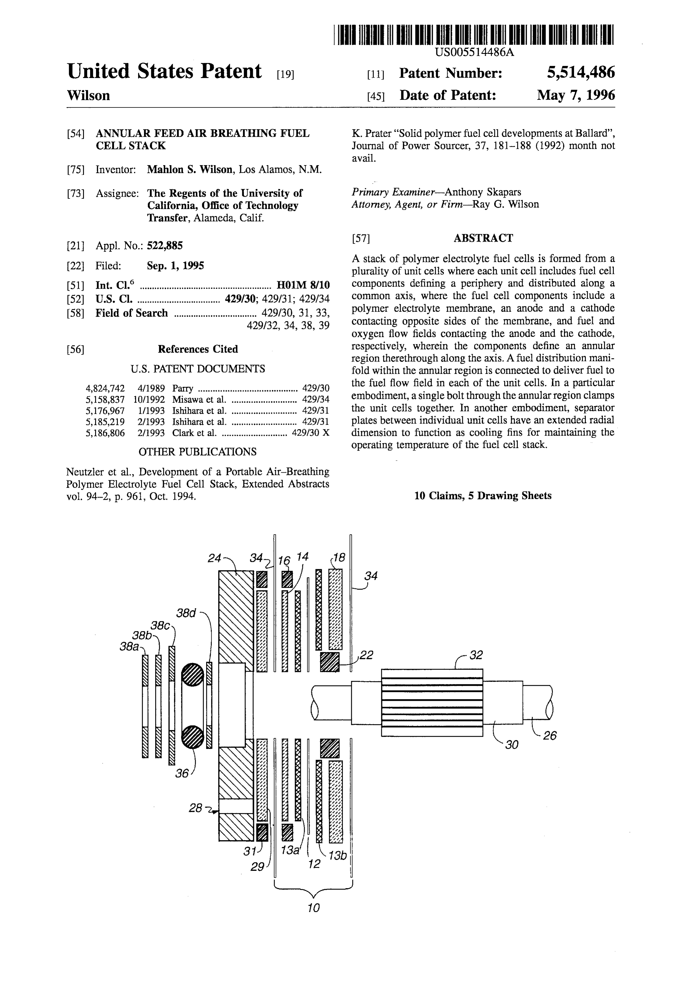
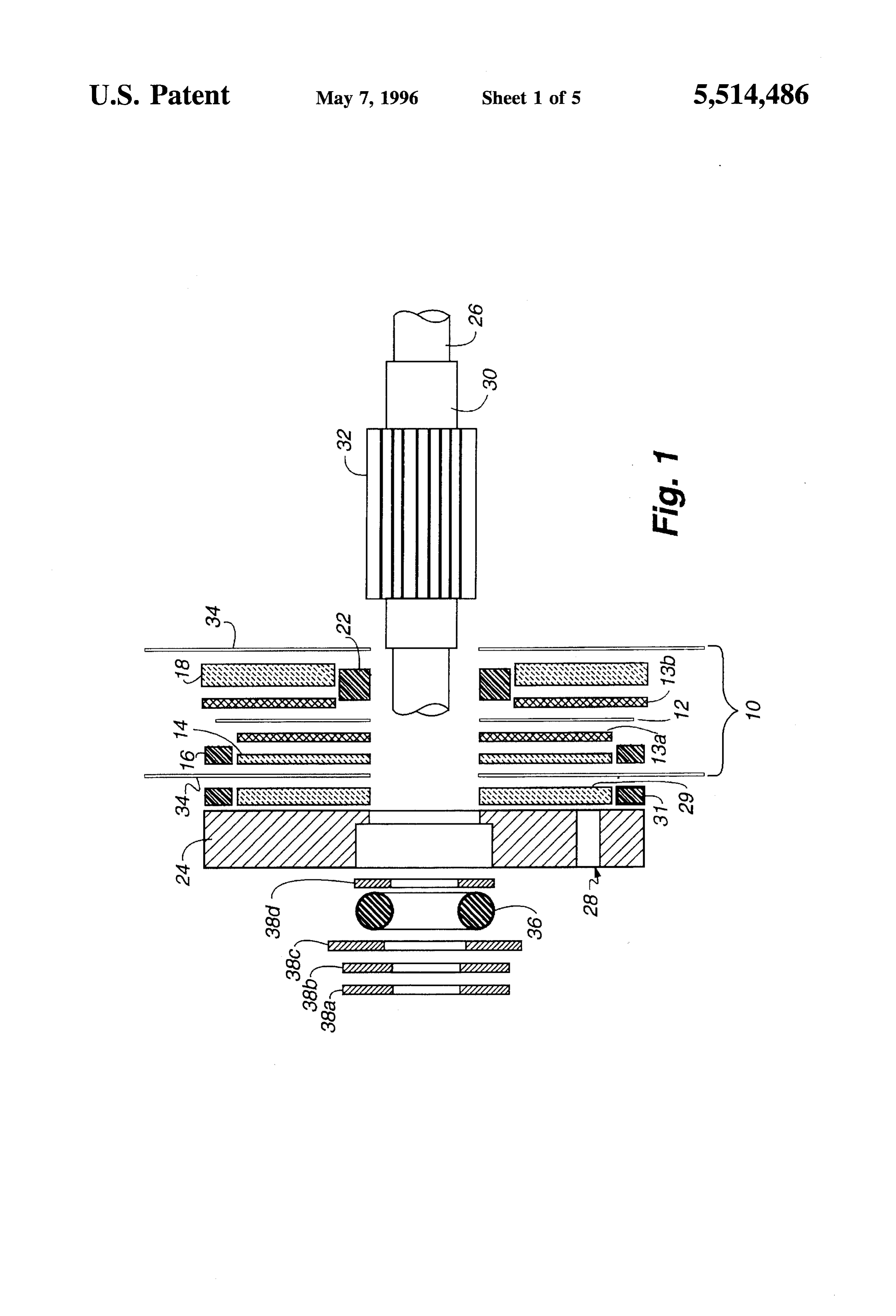
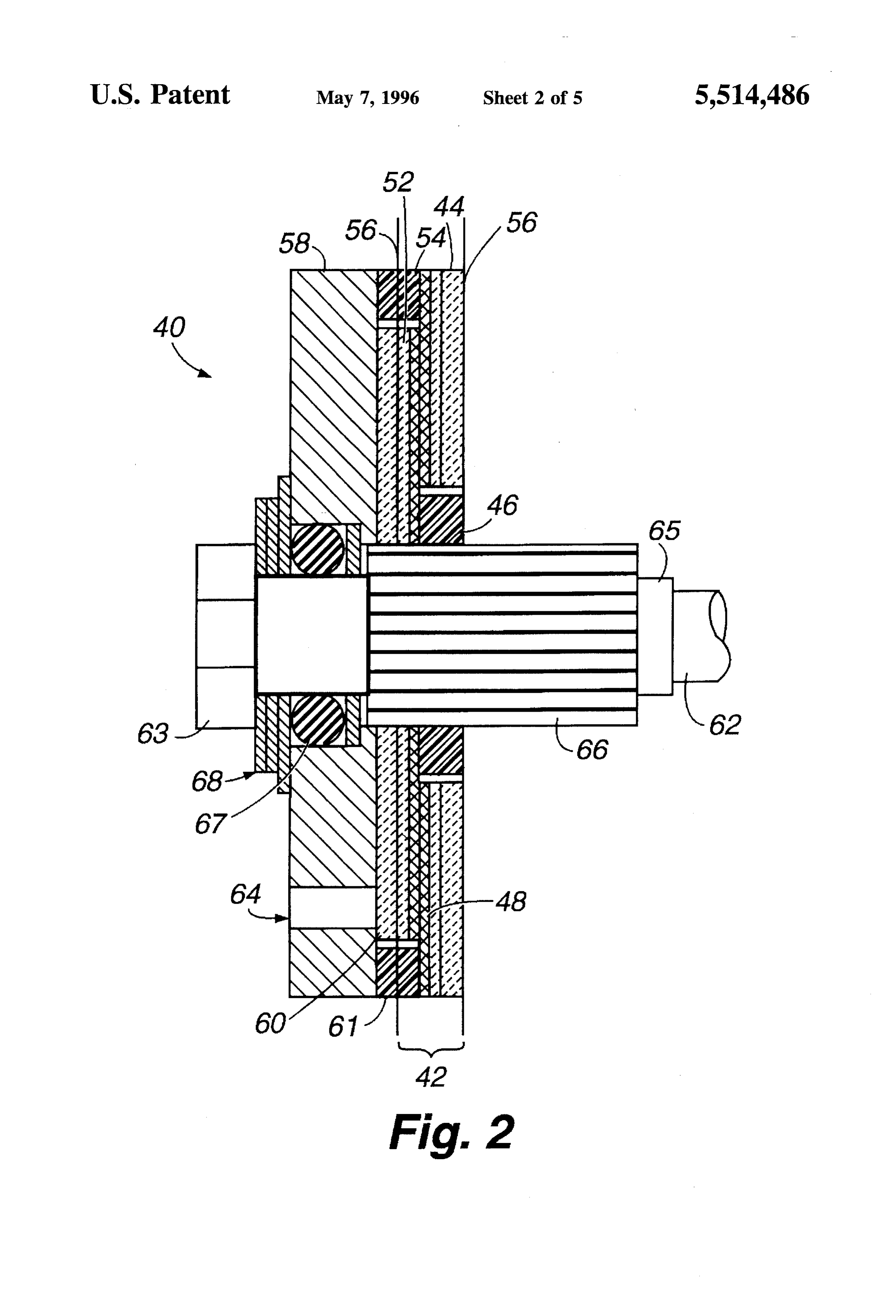
versions of the higher powered pressurized stacks. In most FIG. 1 is an exploded view of a fuel cell according to one cases, the air cathodes are not manifolded, but consist of embodiment of the present invention. plates with large, vertically oriented grooves that allow the FIG. 2 is a cross-sectional view with exaggerated dimen ambient air to flow upward through the warm stack by a chimney effect. While such cells are capable of good per 55 sions to show a stack of fuel cells shown in FIG. 1. formance, the performance may be erratic. While the con FIG. 3 graphically depicts single cell fuel cell perfor siderable amount of free convection that is incurred by the mance at different cathode flow field thicknesses. chimney effect delivers substantial amounts of oxygen, it FIG. 4 graphically depicts the performance of an eight cell can also remove substantial amounts of water. Hence, the stack with 1.5 mm thick cathode flow fields. cells tend to dry out unless special additional precautions are 60 FIG. 5 graphically depicts the power yield of an eight cell taken, e.g., a water reservoir that must be periodically stack with 1.5 mm thick cathode flow fields. replenished. The cells may also tend to overheat when run at DETALED DESCRIPTION OF THE high power and the chimney effect is disrupted if the cells INVENTION are tilted, resulting in a loss of power.
Accordingly, one object of the present invention is a 65 In accordance with the present invention, a polymer PEFC air-breathing stack configuration is provided that is electrolyte fuel cell (PEFC) is provided with the fuel supply relatively independent of stack orientation. outward from an axial central annulus and the oxygen
Page 8
supply inward from the cell periphery. In a preferred geom cells. Sleeve 32 is in communication with the inner edge of etry, circular flow-field and electrode plates are used to fuel flow field plate 14 in each fuel cell so that hydrogen is provide a symmetric configuration that is relatively light diffused along a surface of membrane 12 opposite the weight and easy to manufacture. With the single annular surface receiving oxygen that diffuses through oxygen flow manifold for fuel supply, the entire periphery is free to field plate 18. Impermeable electrically conductive separator oxygen access, which diffuses toward the center through a plate 34 separates flow fields in adjacent fuel cells when the porous flow-field. Typically, the fuel is hydrogen and the cells are assembled into a stack. Separator plate 34 may oxygen is oxygen in ambient air. extend radially from above the periphery of the stack to The application of a diffusion process for the oxygen serve the additional function of a cooling fin. supply acts to limit the supply to the active sites, which 10 Fuel or anode flow field plate 14 is a macroporous limits the reaction, but it also prevents overheating in a electrically conductive material having a relatively small properly designed cell. The porous flow-field also limits the thickness, e.g., about 0.5 mm; oxygen or cathode flow field outward diffusion of the reaction product water, thus mini plate 18 is a macroporous electrically conductive material mizing water loss and drying effects on the cell. Since each having a relatively large thickness, e.g., about 2 mm. A molecule of oxygen diffusing inward produces two water 5 suitable flow field material is a carbon-fiber based paper molecules that diffuse outward at steady-state conditions, it with about 70% porosity and a 30 mm mean pore diameter, will be appreciated that the cell design allows the influx of such as available as Spectracarb 2050 from Spectracorp. sufficient oxygen while limiting the escape of water vapor Inc., Lawrence, Mass.
such that the system maintains the desired high hydration FIG. 2 depicts a cross-sectional view of an assembled fuel level. In addition, the absence of manifold seals at the cell 40. Each unit fuel cell 42 includes air flow field plate 44 periphery of all but the anode flow-fields allows greater with its inner seal 46, catalyzed membrane assembly (mem conduction of reaction heat to the periphery to enhance brane and electrode backings) 48, and fuel flow field plate 52 cooling. In addition, the diffusion delivery of the reactants with outer seal 54, as discussed in FIG. 1. Inner seal 46 and allows the performance of the cells to be relatively tolerant outer seal 54 are not necessarily separate components, but of stack orientation. 25 may be formed by coating the appropriate edge portions In terms of manufacturing advantages, all of the compo with a sealant. Impermeable separator plates 56 separate ments of the stack, such as the flow-fields and seals, are adjacent unit fuel cells. As shown, separator plates 56 have radially symmetrical so fabrication and modifications are an extended diameter to provide an additional function of a simple. In addition, this configuration provides a highly 30 cooling fin during power generation.
efficient utilization of the cross sectional area and smaller The stack assembly is formed by clamping unit cells 42 and lighter end-plates. Thus, the size of the complete fuel together by end plate 58 and a second end plate (not shown) cell stack is less than might be obtained with more conven at the other end of the assembled stack. The end plates must tional designs. be relatively rigid and be electrically conductive. In one Referring now to FIG. 1, there is shown, in expanded, 35 embodiment a two part configuration is used where a light cross-sectional view, one embodiment of a unit fuel cell plus weight aluminum plate is backed by a thin current collector. one end plate according to the present invention. Unit cell 10 In a particular aspect of the present invention, the end includes catalyzed polymer electrolyte membrane assembly plates are clamped together by a single bolt 62 along the axis 12, e.g., a Dow or Nafion membrane between porous elec of all of the stack components. In the embodiment shown in trodes, anode 13aand cathode 13b, such as a graphite cloth 40 FIG. 2, fuel inlet port 64 introduces fuel into fuel flow field or paper, between fuel flow field plate 14 and oxygen flow 60 for diffusion to sleeve 66 for axial annular distribution to field plate 18. Fuel flow field plate 14 is provided with an fuel flow fields 52 in unit fuel cells 42. Sleeve 66 is formed outer seal 16 with anode 13ato prevent the release of fuel from an insulating material and electrically isolated from all from the cell periphery. Oxygen flow field plate 18 is of the individual stack plates. As shown, the head of bolt 62 provided with an inner seal 22 with cathode 13b to separate 45 bears against washer stack 68 to compress O-ring 67 for it from the fuel annulus. sealing the stack and for clamping the stack. Washer stack 68 For a fuel cell at one end of a stack, end plate 24 is may be any convenient arrangement that maintains the provided as a current collector plate and to compress the fuel sealing and clamping force over a range of operating tem cell components as discussed for FIG. 2. Fuel is introduced peratures. Where the end plates are conductive, at least one through port 28. In one embodiment a fuel diffusion flow 50 of the washers in washer stack 68 is non-conductive in order field 29 with outer seal 31 is provided to distribute the fuel to electrically isolate the end plate from bolt 62. as described below. It will be understood that the above description of the fuel Bolt 26 extends through the fuel cell components along cell stack and unit fuel cell components is to a preferred the fuel cell axis. Insulating sleeve 30 shrouds bolt shank 26 embodiment and the invention is not limited to the specific to electrically isolate bolt 26 from end plate 24. The entrance 55 exemplary materials. For example, the porous flow-fields of bolt 26 through end plate 24 is sealed by the compression could be metal screens or bonded particles; the membrane of O-ring 36 between washers 38a–d. Sleeve 32 forms an assembly could use any number of low or high platinum axial annular region about bolt 26 and acts as a distribution loading technologies; the flow-fields and impermeable bar manifold to distribute fuel from fuel inlet flow field 29 rier could be a single, monolithic bipolar plate, and so forth. axially along fuel cell 10. Sleeve 32 is preferably formed of 60 FIG. 3 graphically illustrates the performance of a single a hydrophilic or hydrophilic-treated porous tube. The pre unit fuel cell at different oxygen/cathode flow-field thick ferred design includes axial channels along the periphery. nesses of 1.5, 2.5, and 4.5 mm. The unit cells were formed Fuel flow is along the channels to fuel flow field 14. Water from a polymer electrolyte membrane catalyzed with thin accumulates in and is distributed along the cell by the film catalyst layers with low platinum loadings (about 0.15 wicking action of porous tube 32. Thus, in a stack of unit 65 mg Pt/cm/electrode as described in U.S. Pat. Nos. 5,211, cells 10, water does not accumulate at the downstream end 984 and 5,234,777, incorporated herein by reference). The of the stack and block the access of fuel to the individual catalyzed membranes were sandwiched between uncata
Page 9
lyzed ELAT backings (E-TEK, Inc., Natick, Mass.). The various modifications as are suited to the particular use outside diameter of the hardware was about 5 cm and the contemplated. It is intended that the scope of the invention cells had an active area of about 13 cm. The cells were be defined by the claims appended hereto. operated at an ambient pressure of about 0.75 atm (ambient What is claimed is:
pressure at laboratory elevation). Hydrogen fuel was sup 5 1. A polymer electrolyte fuel cell comprising: plied to the annular plenum at 5 psig. The porous flow fields fuel cell components defining a periphery and distributed were formed from Spectracarb 2050 material, described along a common axis, said fuel cell components com above. The cells provided steady long-term performance, prising a polymer electrolyte membrane, an anode and indicating that the cells were maintaining a sufficiently high a cathode contacting opposite sides of said membrane, hydration level for the membranes. As shown in FIG. 3, the 10 and fuel and oxygen flow fields contacting said anode thicker flow-fields provided higher currents when the tem and said cathode, respectively, wherein said compo peratures were controlled around 50° C. and delivered about a watt of power at about 0.5 V. nents define an annular region therethrough along said Typically, unit fuel cells are arranged in series to form a axis; and stack of cells for the delivery of more power and higher 15 a fuel distribution manifold within said annular region voltage. When the cells are stacked to output more power, connected to deliver fuel to said fuel flow field. the concerns of overheating and hence sufficient hydration 2. A polymer electrolyte fuel cell according to claim 1, become more significant. In FIG. 4 is shown a polarization wherein said oxygen flow field is open at said periphery of curve of an eight cell stack for a cathode flow-field thickness said fuel cell components for oxygen movement from said of 1.5 mm. Every two cells were separated by impermeable 20 periphery toward said annular region.
stainless steel plates having a diameter of 6.4 cm vs. 5 cm 3. A polymer electrolyte fuel cell according to claim 1, for the unit cell and serve as cooling fins. The stack wherein said fuel flow field is sealed at said periphery of said temperature rarely exceeded about 55° C. with the fins. The fuel cell and said oxygen flow field is sealed at said annular stack of unit cells is about 2 cm thick. The corresponding 25 region.
power output from the fuel cell stack is shown in FIG.5. An 4. A stack of polymer electrolyte fuel cells comprising: output power up to 5W was obtained at a cathode flow field a plurality of unit cells where each unit cell includes fuel thickness of 1.5 mm. cell components defining a periphery and distributed The power densities of the stacks do not suffer as the along a common axis, said fuel cell components com thickness of the unit cells is decreased because it is then prising a polymer electrolyte membrane, an anode and possible to fit in more cells per unit stack volume. The 30 a cathode contacting opposite sides of said membrane, drawbacks are that the device voltage increases with the and fuel and oxygen flow fields contacting said anode increased number of cells and the device cost increases and said cathode, respectively, wherein said compo because of the increased number of components. If the nents define an annular region therethrough along said performance of the 1.5 mm cells is maintained over a 35 axis; and multi-cell stack, then 25W could be delivered from a device a fuel distribution manifold within said annular region with 40 cells that is about 6.4 cm (2.5 in) in diameter connected to deliver fuel to said fuel flow field in each (including fins) and is 8 cm long, not including the contri of said unit cells.
butions of the endplates and bolt. 5. A stack of polymer electrolyte fuel cells according to It will be appreciated that one of the strengths of a fuel cell 40 claim 4, wherein said oxygen flow field is open at said stack according to the present invention is that a very periphery of said fuel cell components for oxygen move compact package can be provided. For example, an attrac ment from said periphery toward said annular region. tive package for using a small fuel cell system is a D-cell 6. A stack of polymer electrolyte fuel cells according to size stack combined with a metal hydride canister (HCI, claim 4, wherein said fuel flow field is sealed at said Littleton, Colo.) that supplies 7.2V, as is obtained from a 45 periphery of said fuel cell and said oxygen flow field is six-pack of D-cell Nicad batteries. The sizes of the two sealed at said annular region.
systems are about the same, yet the fuel cell system yields 7. A stack of polymer electrolyte fuel cells according to more than three times more energy than the battery system claim 4, further including two end plates for clamping (ca. 48 W hr vs. 15 W hr). Furthermore, a replacement together said fuel cell components, where at least one of said hydride canister can be used immediately for continuous 50 end plates includes a fuel inlet port.
uninterrupted operation. It should be noted, however, that 8. A stack of polymer electrolyte fuel cells according to the fuel cell system is not capable of delivering power levels claim 7, further including a fuel inlet flow field for distrib as high as nickel-cadmium batteries so it will not be an uting fuel from said inlet port to said annular region. effective replacement for all applications. 9. A stack of polymer electrolyte fuel cells according to The foregoing description of the invention has been 55 claim 7, further including a single clamping bolt extending presented for purposes of illustration and description and is through said annular region for urging said end plates not intended to be exhaustive or to limit the invention to the together and clamping said fuel cell components therebe precise form disclosed, and obviously many modifications Ween.
and variations are possible in light of the above teaching. 10. A stack of polymer electrolyte fuel cells according to The embodiments were chosen and described in order to 60 any one of claims 4-6 or 7-9, wherein each one of said fuel best explain the principles of the invention and its practical cell components is radially symmetric about said axis. application to thereby enable others skilled in the art to best utilize the invention in various embodiments and with ck : : k :
Provenance
- Collection
- Cited prior art
- Original PDF
- patentimages.storage.googleapis.com →
- Filed
- 1995-09-01
- Pages
- 9
- Method
- pdftotext (the PDF's own text layer) + pdftoppm 300dpi page scans
- Source
- Google Patents bibliographic record
- Granted
- 1996-05-07
- Inventors
- Mahlon S. Wilson; University of California Berkeley
- Transcribed from
- patentimages.storage.googleapis.com →