patent · US5470671
Electrochemical fuel cell employing ambient air as the oxidant and coolant
28 November 1995
Page 1 — bibliographic record
United States Patent (19) 11) Patent Number: 5,470,671 Fletcher et al. 45) Date of Patent: Nov. 28, 1995 54) ELECTROCHEMICAL FUEL CELL 5,108,849 4/1992 Watkins et al.. EMPLOYING AMBENT AIR AS THE 5,190,834 3/1993 Kendall.
OXDANT AND COOILANT 5,242,764 9/1993 Dhar .......................................... 429/30 5,284,718 2/1994 Chow et al. ......... ... 429/26 (75) Inventors: Nicholas J. Fletcher; Gordon J. 5,300,370 4/1994 Washington et al. ..................... 429/34 Lamont, both of Vancouver, Vesna Primary Examiner-Prince Willis, Jr.
Basura, Burnaby; Henry H. Voss, West Assistant Examiner-M. Nuzzolillo
Vancouver, David P. Wilkinson, North Attorney, Agent, or Firm-McAndrews, Held & Malloy,
73) Assignee: Ballard Power Systems Inc., North 57) ABSTRACT Vancouver, Canada
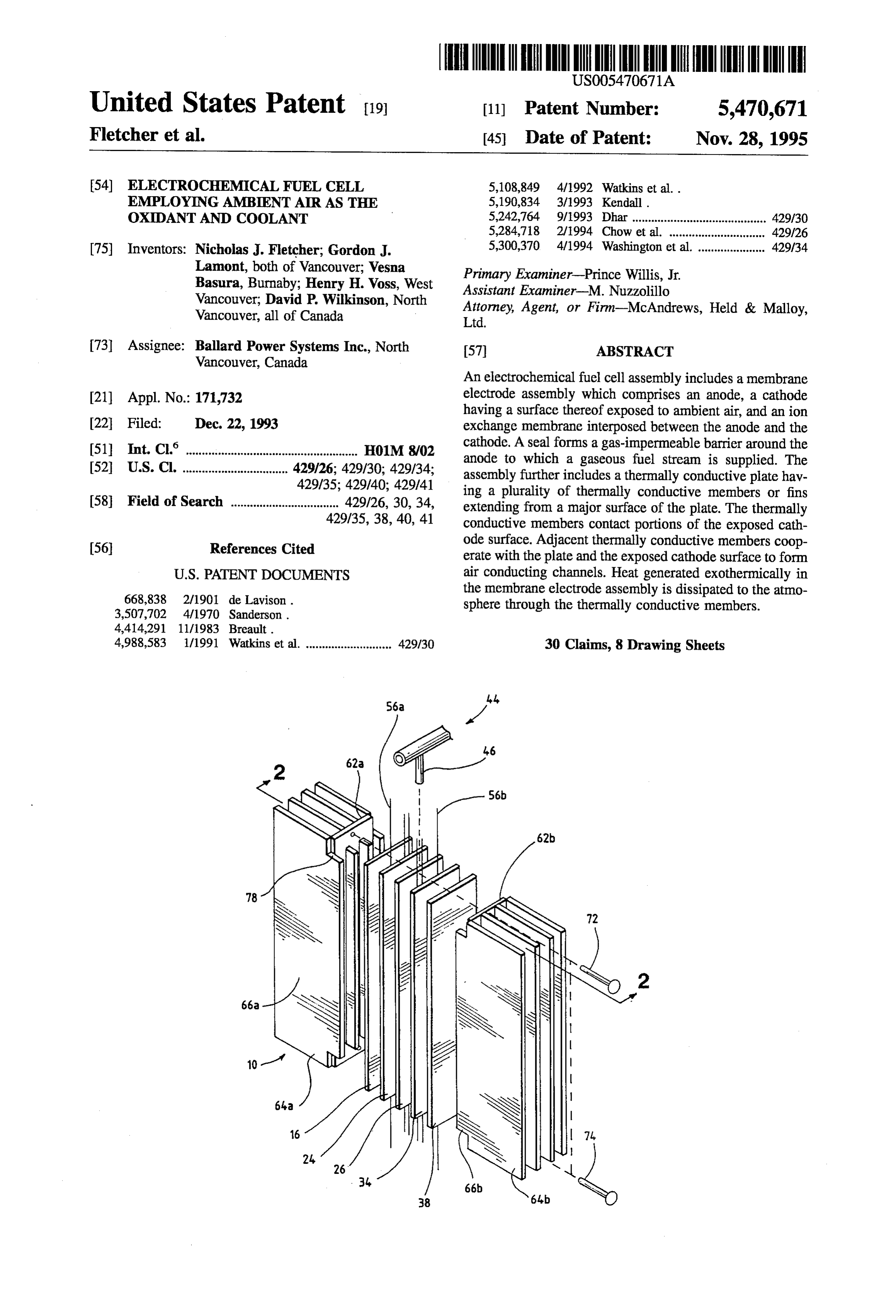
An electrochemical fuel cell assembly includes a membrane 21) Appl. No.: 171,732 electrode assembly which comprises an anode, a cathode having a surface thereof exposed to ambient air, and an ion 22 Filed: Dec. 22, 1993 exchange membrane interposed between the anode and the 51 Int. Cl. ... H01M. 8/02 cathode. A seal forms a gas-impermeable barrier around the 52 U.S.C. ................................. 429/26; 429/30, 429/34; anode to which a gaseous fuel stream is supplied. The 429/35; 429/40, 429/41 assembly further includes a thermally conductive plate hav (58) Field of Search .................................. 429/26, 30, 34, ing a plurality of thermally conductive members or fins extending from a major surface of the plate. The thermally 429/35, 38, 40, 41 conductive members contact portions of the exposed cath (56) References Cited ode surface. Adjacent thermally conductive members coop erate with the plate and the exposed cathode surface to form
the membrane electrode assembly is dissipated to the atmo
sphere through the thermally conductive members.
4,988,583 1/1991 Watkins et al. ........................... 429/30 30 Claims, 8 Drawing Sheets
Page 2
Drawing sheet — no readable text.
Page 3
Drawing sheet — no readable text.
Page 4
Drawing sheet — no readable text.
Page 5
Drawing sheet — no readable text.
Page 6
Drawing sheet — no readable text.
Page 7
Drawing sheet — no readable text.
Page 8
Drawing sheet — no readable text.
Page 9
Drawing sheet — no readable text.
Page 10
ELECTROCHEMICAL FUEL CELL passages direct the fuel and oxidant to the respective elec EMPLOYING AMBENT AIR AS THE trodes, namely, the anode on the fuel side and 10 the cathode OXDANT AND COOLANT on the oxidant side. The electrodes are electrically coupled to provide a path for conducting electrons between the electrodes.
FIELD OF THE INVENTION In a single cell arrangement, fluid flow field plates are This invention relates generally to electrochemical fuel provided on each of the anode and cathode sides. The plates cells and, more particularly, to a fuel cell which employs act as current collectors, provide support for the electrodes, ambient air as both an oxidant and a coolant. provide access channels for the fuel and oxidant to the 10 respective anode and cathode surfaces, and provide channels
BACKGROUND OF THE INVENTION for the removal of waterformed during operation of the cell. Two or more fuel cells can be connected together in series
A fuel cell is a device which generates electrical energy by or in parallel to increase the overall power output of the converting chemical energy directly into electrical energy by 15 assembly. In such arrangements, the cells are typically oxidation of fuel supplied to the cell. Fuel cells are advan connected in series, wherein one side of a given plate serves tageous because they convert chemical energy directly to as an anode plate for one cell and the other side of the plate electrical energy without the necessity of undergoing any is the cathode plate for the adjacent cell. Such a series intermediate steps, for example, combustion of a hydrocar connected multiple fuel cell arrangement is referred to as a bon or carbonaceous fuel as takes place in a thermal power 20 fuel cell stack, and is usually held together by tie rods and station. end plates. The stack typically includes manifolds and inlets for directing the fuel (substantially pure hydrogen, methanol
A typical fuel cell includes an anode, a cathode and an reformate electrolyte. Fuel and oxidant are supplied to the anode and or natural gas reformate) and the oxidant (sub cathode, respectively. At the anode, the fuel permeates the stantially pure oxygen or oxygen-containing air) to the anode and cathode flow field channels. The stack also electrode material and reacts with an anode catalyst layer to form cations (protons) and electrons. The cations migrate 25 usually includes a manifold and inlet for directing the coolant fluid, typically water, to interior channels within the through the electrolyte to the cathode. At the cathode, the oxygen-containing gas supply reacts with a cathode catalyst stack to absorb heat generated by the exothermic reaction of layer to form anions. The electrons produced at the anode hydrogen and oxygen within the fuel cells. The stack also travel from the fuel cell anode, through an external load, and generally includes exhaust outlets and manifolds for expel backinto the cathode of the cell. The anions produced at the 30 ling the unreacted fuel and oxidant gases, each carrying entrained water, as well as an outlet manifold for the coolant cathode react with the cations and electrons to form a reaction product which is removed from the cell. water exiting the stack.
In electrochemical fuel cells employing hydrogen as the Conventional fuel cell and stack designs have several fuel and oxygen-containing air (or pure oxygen) as the 35 employ disadvantages.
inherent liquid cooling
First, conventional designs typically systems for regulating the cells' oxidant, a catalyzed reaction at the anode produces hydrogen operating temperature. Liquid cooling systems are disad cations from the fuel supply. This type of fuel cell is vantageous because they require the incorporation of addi advantageous because the only reaction product is water. An tional components to direct coolant into thermal contact with ion exchange membrane facilitates the migration of hydro fuel cells. The power requirements to operate such addi gen cations from the anode to the cathode. In addition to conducting hydrogen cations, the membrane isolates the tional sent components, such as pumps and cooling fans, repre an additional parasitic load on the system, thereby hydrogen fuel stream from the oxidant stream comprising decreasing the net power derivable from the stack. Such oxygen containing air. At the cathode, oxygen reacts at the additional components also add volume, weight, complexity catalyst layer to form anions. The anions formed at the and cost to fuel cell designs.
cathode react with the hydrogen ions that have crossed the 45 Second, conventional designs employ further parasitic membrane to form liquid water as the reaction product. The devices such as pumps for the delivery of pressurized fuel anode and cathode reactions in such fuel cells is shown in the following equations: and oxidant to the fuel cell. In addition to adding volume, weight, complexity and cost, these parasitic systems also
Anode reaction: H-2H-2e reduce the overall power efficiency of the system. 50 Third, in conventional stack arrangements it is difficult to
Cathode reaction: AO-2 H'+2 - H2O identify and replace defective fuel cells without disrupting the operation of the entire fuel cell stack.
A type of fuel cell known as a solid polymer fuel cell The present invention is directed to circumventing one or ("SPFC') contains a membrane electrode assembly more of the above-mentioned disadvantages. Other objects (“MEA") consisting of a solid polymer electrolyte or ion 55 and advantages of the invention will become apparent upon exchange membrane disposed between two electrodes reading the following detailed description and appended formed of porous, electrically conductive sheet material. claims, and upon reference to the accompanying drawings. The electrodes are typically formed of carbon fiber paper (“CFP"), and are generally impregnated or coated with a SUMMARY OF THE INVENTION hydrophobic polymer, such as polytetrafluoroethylene. The 60
MEA contains a layer of catalyst at each membrane/elec The above and other objects are achieved by an electro trode interface to induce the desired electrochemical reac chemical fuel cell assembly comprising: tion. A finely divided platinum catalyst is typically (a) a membrane electrode assembly comprising a porous employed. The MEA is in turn disposed between two electrically conductive anode, a porous electrically electrically conductive plates, each of which has at least one 65 conductive cathode having a surface thereof exposed to flow passage engraved or milled therein. These fluid flow ambient air, and an ion exchange membrane interposed field plates are typically formed of graphite. The flow between the anode and the cathode;
Page 11
(b) sealant means for forming a gas-impermeable barrier share a common ion exchange membrane. around the anode; The above and other objects are also achieved by an (c) fuel delivery means for supplying a gaseous fuel electrochemical fuel cell assembly comprising: stream to the anode; (aa) a bicell membrane electrode assembly comprising a (d) electrical connection means for providing an electrical first porous electrically conductive cathode having a connection to the anode and to the cathode; and surface thereof exposed to ambient air, a porous elec (e) a thermally conductive plate having a plurality of first trically conductive anode, a second porous electrically thermally conductive members extending from a major conductive cathode having a surface thereof exposed to Surface of the plate, the first members contacting por ambient air, a first ion exchange membrane interposed tions of the exposed cathode surface, adjacent ones of O between the first cathode and the anode, and a second the first members cooperating with the plate and the ion exchange membrane interposed between the second exposed cathode surface to form at least one air con cathode and the anode, ducting channel. (bb) sealing means for forming a gas-impermeable barrier In operation, at least a portion of the heat generated around the anode, exothermically in the membrane electrode assembly is dis 15 (cc) fuel delivery means for delivering gaseous fuel to the sipated to the atmosphere through the first members. anode,
The thermally conductive plate is preferably, but not (dd) electrical connection means for providing an electri necessarily, formed as a single planar piece from which the cal connection to the anode, to the first cathode and to thermally conductive members extend. Alternatively, the the second cathode;
plate could consist of a plurality of staggered bars intercon 20 (ee) a first thermally conductive plate having a plurality of necting the thermally conductive members, which extend first thermally conductive members extending from a from the staggered bars and contact the exposed cathode major surface of the plate, the first members contacting surface. portions of the exposed first cathode surface, adjacent The plate and the first members are preferably formed of ones of the first members cooperating with the first aluminum, and the portions of the first members which 25 plate and the exposed first cathode surface to form at contact the cathode surface have an inert metal applied least one air conducting channel; and thereto. The inert metal is preferably gold applied by elec (f) a second thermally conductive plate having a plurality troplating. of second thermally conductive members extending The preferred electrical connection means comprises from a major surface thereof, the second members electrical conductors disposed between the anode and the 30 contacting portions of the exposed second cathode ion exchange membrane, and the electrical conductors pref. surface, adjacent ones of the second members cooper erably extend through the sealing means. The preferred ating with the second plate and the exposed second electrical conductors are formed from gold wire. cathode surface to form at least one air conducting In the preferred assembly, the plate has a thermally channel.
conductive material extending from another major surface of 35 In operation, at least a portion of the heat generated exo the plate, such that heat generated exothermically in the thermically in the bicell membrane electrode assembly is membrane electrode assembly is further dissipated to the dissipated to the atmosphere through the first and second atmosphere through the material. The material preferably members.
comprises a plurality of thermally conductive members, or The first and second members are preferably formed of alternatively a thermally conductive foam. The preferred 40 aluminum, the portions of the first and second members thermally conductive foam is an aluminum foam. which contact the cathode surfaces have an inert metal In the preferred assembly, the fuel delivery means com applied thereto. The inert metal is preferably gold applied by prises a fuel inlet and a fuel outlet, such that the fuel outlet electroplating.
directs unreacted components of the gaseous fuel stream The electrical connection means preferably comprises away from the anode. The assembly can further comprise a 45 first electrical conductors disposed between the anode and fan for directing the ambient air onto the exposed surface of the first membrane, and second electrical conductors dis the porous electrically conductive cathode. Where the gas posed between the anode and the second membrane, such eous fuel stream comprises hydrogen, the assembly prefer that the first and second electrical conductors extending ably further comprising means for accumulating water con through the sealing means. The first and second electrical densed on the first thermally conductive members. 50 conductors are preferably formed from gold wire. A fuel cell stack incorporating the above fuel cell assem In the preferred bicell assembly, the first plate has a first blies comprises: thermally conductive material extending from another major 1. a plurality of fuel cell assemblies as defined with Surface of the first plate, and the second plate has a second components (a)-(e) above, thermally conductive material extending from another major 55 Surface of the second plate, such that heat generated exo 2. serial connection means for electrically connecting the thermically in the bicell membrane electrode assembly is plurality of fuel cell assemblies in an electrical series further dissipated to the atmosphere through the first and having a first assembly and a last assembly, wherein the second material. The first and second material each prefer anode of each assembly except the last assembly in the series is electrically connected to the cathode of the 60 or alternatively a thermallyofconductive ably comprises a plurality thermally conductive members, foam. The preferred next adjacent assembly in the series; thermally conductive foam is an aluminum foam. 3. a positive current lead electrically connected to the In the preferred bicell assembly, the sealing means com cathode of the first assembly in the series; and prises the first and second membranes, such that the edges 4. a negative current lead electrically connected to the of the first and second membranes are bonded together to anode of the last assembly in the series. 65 form a gas-impermeable barrier around the anode. The fuel cell stack can be formed as a multiplexed In the preferred bicell assembly, the fuel delivery means arrangement, wherein the plurality of fuel cell assemblies comprises a fuel inlet and a fuel outlet, such that the fuel
Page 12
outlet directs unreacted components of the gaseous fuel FIG. 10 is a side view of the pivotable baffle subassembly stream away from the anode. The preferred bicell assembly shown in FIG. 9.
further comprises a fan for directing the ambient air onto the FIB. 11 is a schematic view of third embodiment of an exposed surface of the porous electrically conductive cath electrochemical fuel cell assembly employing ambient air as ode. Where the gaseous fuel stream comprises hydrogen, the the oxidant and coolant, which employs external dampers bicell assembly preferably further comprising means for for adjusting the flow through the air conducting channels. accumulating water condensed on the first and second thermally conductive members. DETAILED DESCRIPTION OF THE A bicell stack incorporating the above bicell assemblies PREFERRED EMBODIMENTS comprises: 10
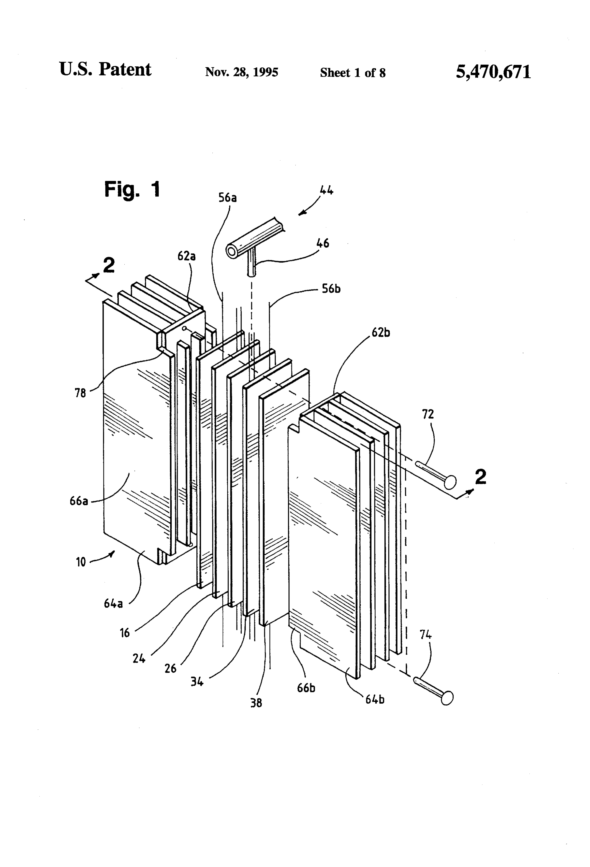
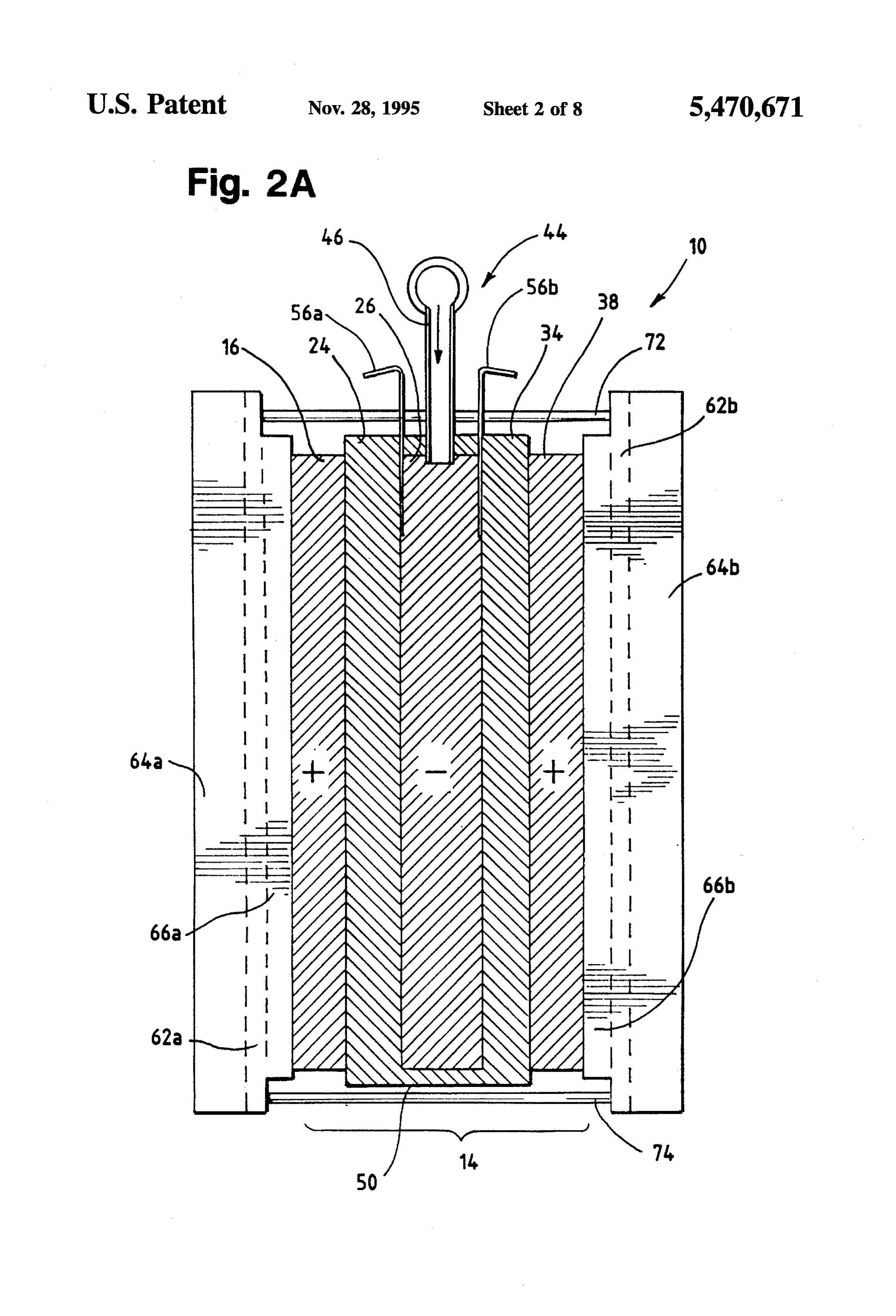
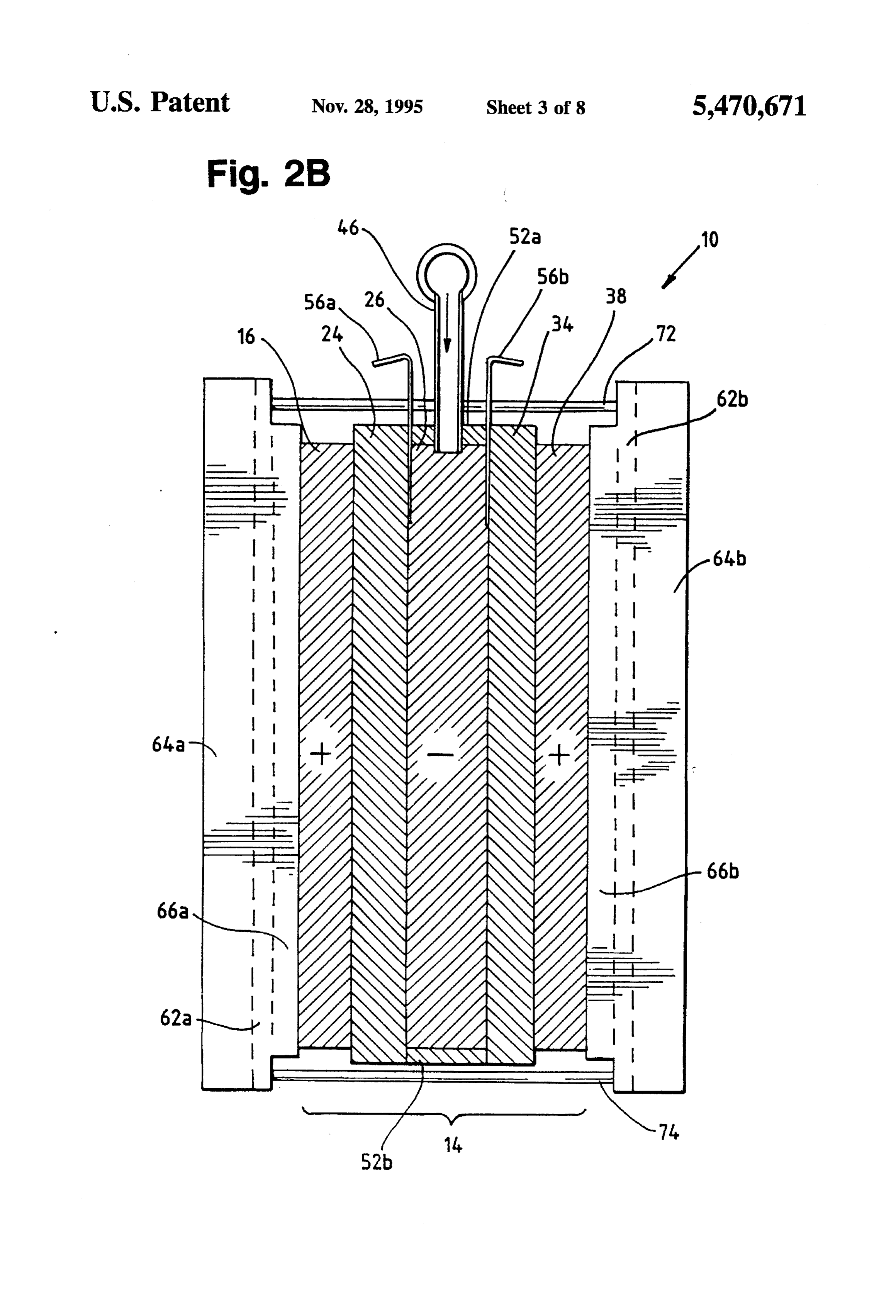
I. a plurality of fuel cell assemblies as defined with Referring first to FIG. 1 and FIG. 2A, an electrochemical components (aa)-(f) above; fuel cell assembly 10, includes a bicell membrane electrode II. serial connection means for electrically connecting the assembly ("MEA') 14. Bicell MEA 14 includes a first plurality of bicell assemblies in an electrical series 15 cathode 16, an anode 26, and a second cathode 38. A firstion having a first assembly and a last assembly, wherein the exchange membrane 24 is interposed between first cathode anode of each assembly except the last assembly in the 16 and anode 26. A second ion exchange membrane 34 is series is electrically connected to the cathodes of the interposed between second cathode 38 and anode 26. Fuel next adjacent assembly in the series; supply line 44 and fuel inlet 46 contain and direct fuel at a III. a positive current lead electrically connected to the 20 pressure slightly greater than atmospheric to anode 26. cathodes of the first assembly in the series; and The electrodes 16, 26, 38 are formed of porous electri IV. a negative current lead electrically connected to the cally conductive sheet material, preferably porous carbon anode of the last assembly in the series. fiber paper ("CFP") impregnated or coated with a hydro The bicell stack can be formed as a multiplexed arrange phobic polymer, such as polytetrafluoroethylene. The elec ment, wherein the plurality of bicell assemblies share a 25 such as16, trodes 26, 38 are each treated with a layer of catalyst, platinum or other suitable electrocatalytic material, common first ion exchange membrane and a common sec ond ion exchange membrane. on the surface(s) adjacent and in contact with the ion exchange membrane(s) 24, 34 to facilitate the desired chemical reaction. Suitable ion exchange membranes are
BRIEF DESCRIPTION OF THE DRAWINGS 30 commercially available from DuPont under the trade name
Nafion 117 and from Dow under the trade designation XUS
FIG. 1 is an exploded perspective view of an electro 13204.10.
chemical fuel cell assembly employing ambient air as the The electrodes 16, 26, 38 and the ion exchange mem oxidant and coolant.
FIG. 2A is a section view taken in the direction of arrows branes 24, 34 are arranged together in an interleaved or 2-2 in FIG. 1. 35 sandwich-like manner, as illustrated in FIG. 1 and FIG. 2A, and placed in a high pressure press at a temperature suffi
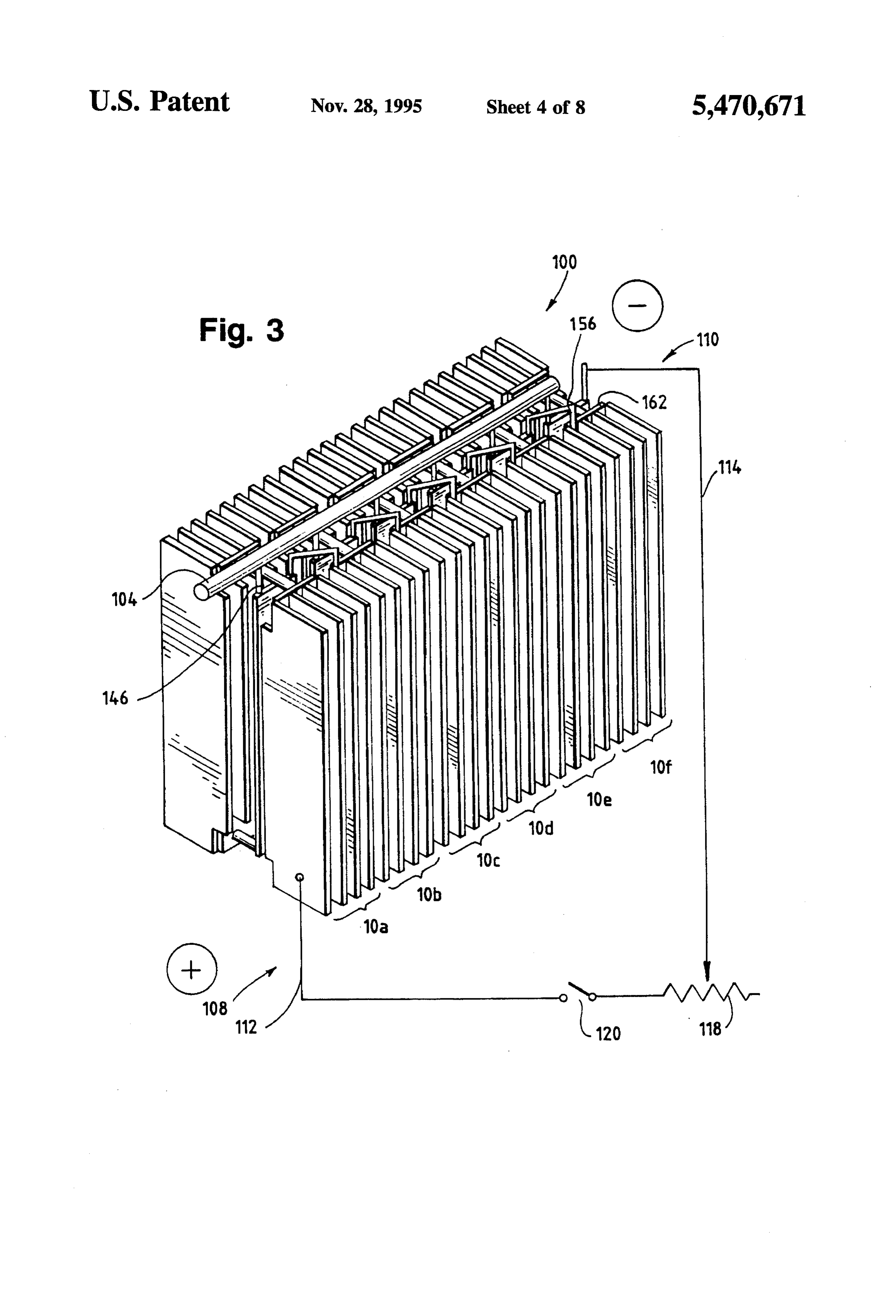
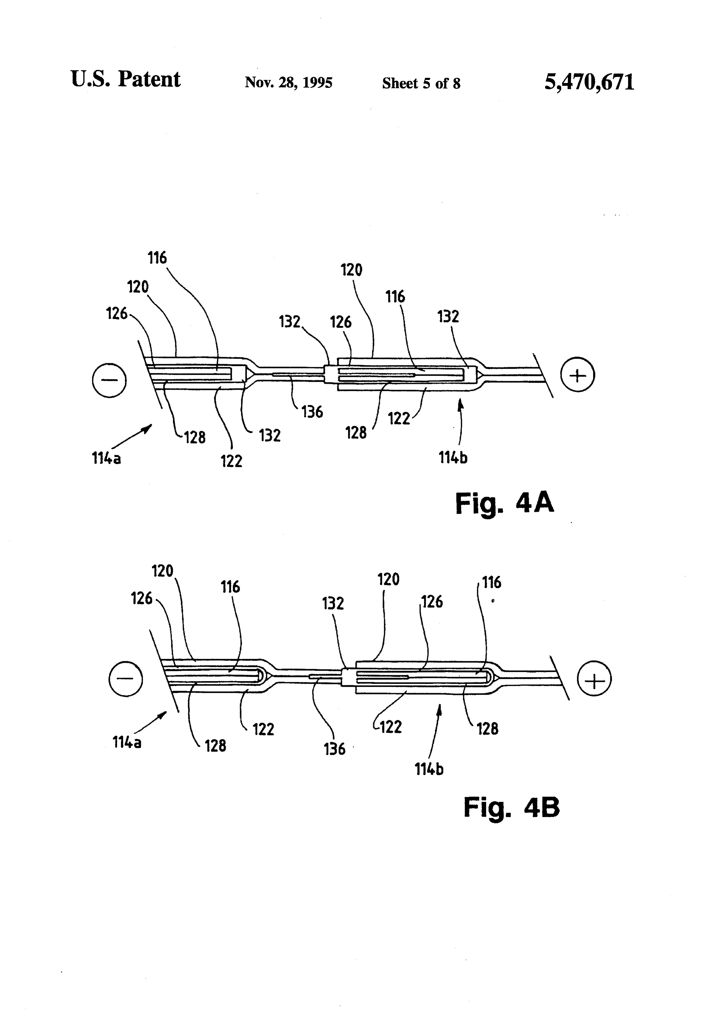
FIG. 2B is section view of an alternative embodiment of cient to soften the ion exchange membrane material. The the electrochemical fuel cell assembly illustrated in FIGS. 1 combination of pressure and temperature forces the softened and 2A. membrane material at least partially into the CFP electrode FIG. 3 is a perspective view of a fuel cell stack connected 40 material, bonding the individual layers to form a single across an external load. unitary assembly. Presently, the bicell MEA 14 is formed by FIGS. 4A and 4B illustrate alternative embodiments of an placing the layers of material in a press at a temperature and interleaved membrane electrode assembly according to the pressure sufficient to soften the material and create an present invention. intimate bond.
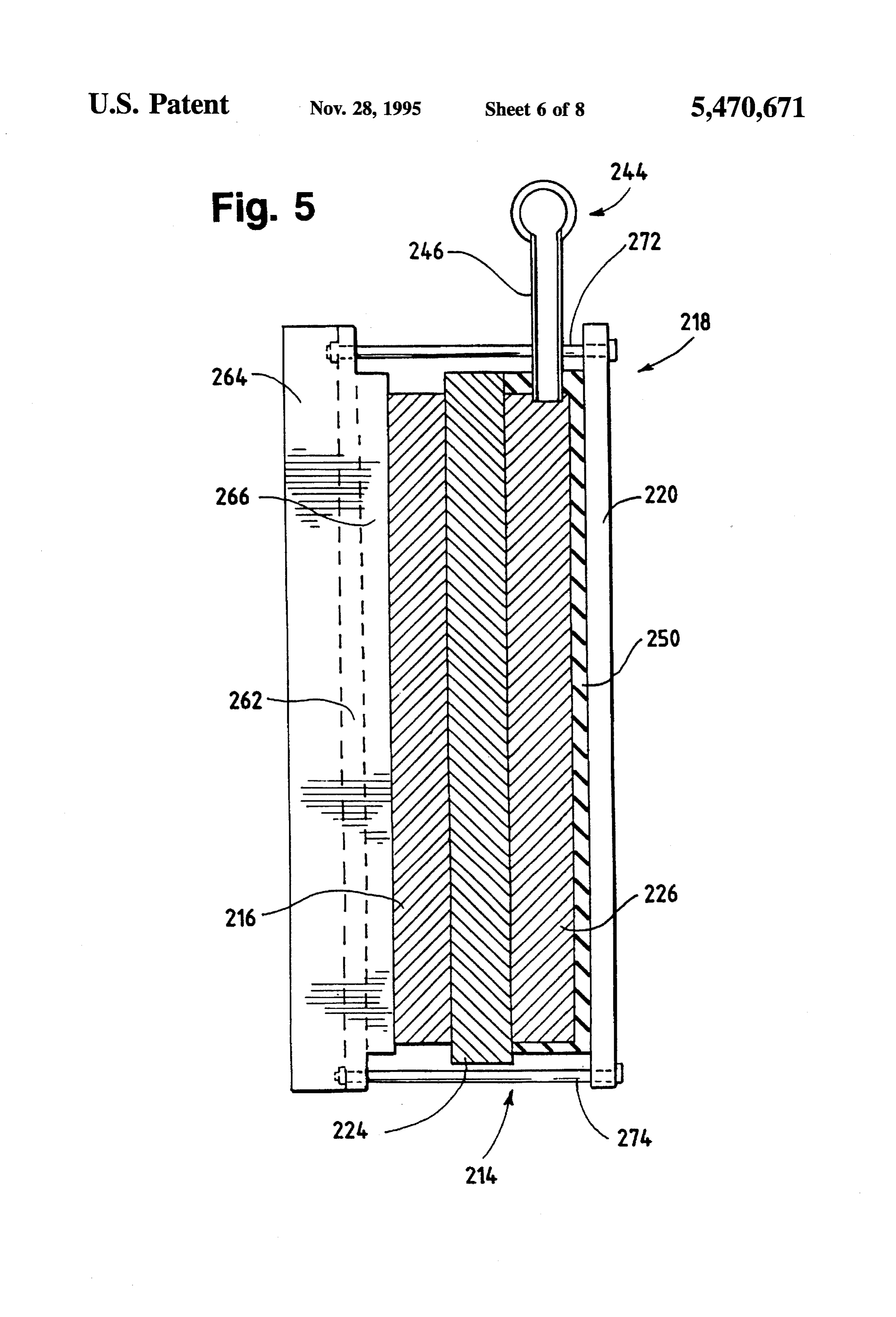
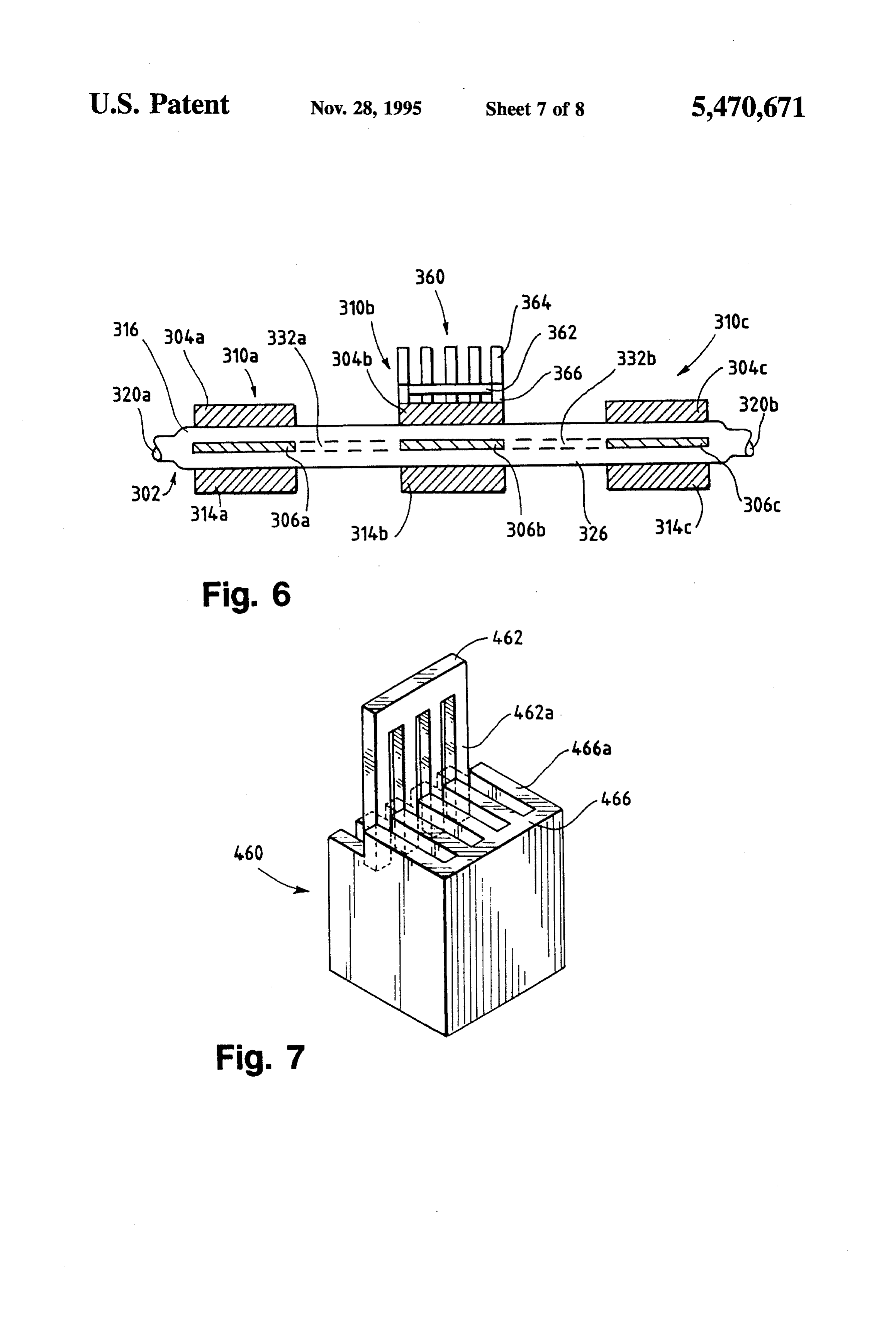
FIG. 5 is a side sectional view of an alternative embodi 45 Low pressure can be employed to supply the gaseous fuel ment of an electrochemical fuel cell assembly employing because the chemical reaction at the anode 26 consumes the ambient air as the oxidant and coolant. fuel and draws it into the anode 26. The porous structure of FIG. 6 is a sectional view of a multiplexed arrangement the CFP used to form the anode 2G facilitates the delivery of three bicell membrane electrode assemblies employing 50 fuelof the gaseous fuel throughout the anode 26. The gaseous ambient air as the oxidant and coolant, which share common reacts at the anode 26 to produce cations (protons) and ion exchange membranes. electrons. When hydrogen is used as the fuel, the reaction at the anode produces hydrogen cations and electrons accord
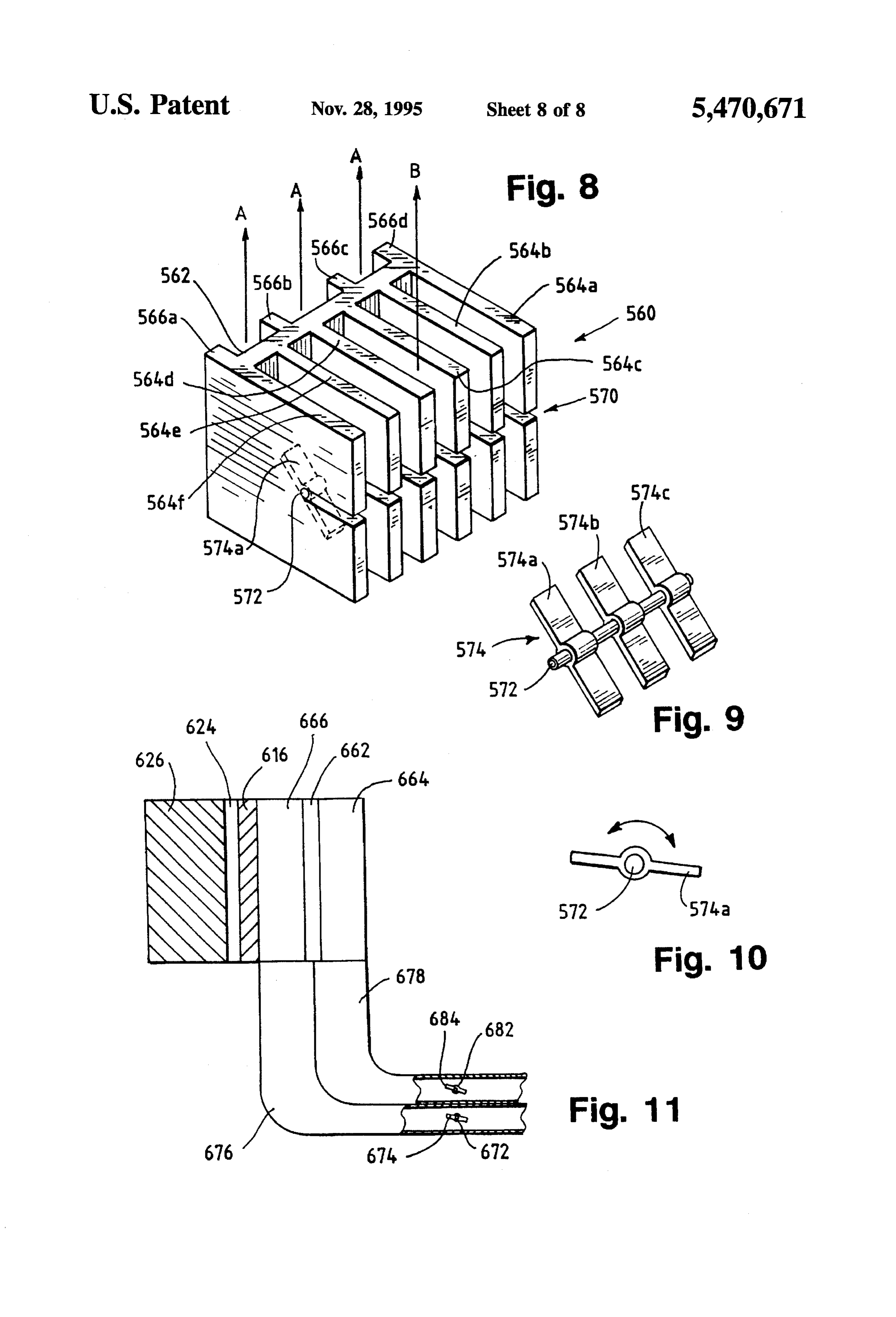
FIG. 7 is an exploded perspective view of a first embodi ing to the following equation:
ment of a thermally conductive member or fin subassembly for an electrochemical fuel cell assembly employing ambi 55 ent air as the oxidant and coolant, which employs a slidable comb for adjusting the configuration of the air conducting The reaction at the cathodes 16, 38 produces water channels. according to the following equation: FIG. 8 is a perspective view of second embodiment of a thermally conductive member or fin subassembly for an 60 electrochemical fuel cell assembly employing ambient air as The ion exchange membrane facilitates the migration of the oxidant and coolant, which employs a pivotable baffle cations from the anode 26 to the cathodes 16, 38. In addition (shown in phantom lines) for adjusting the flow through the to conducting hydrogen cations, the ion exchange mem air conducting channels. branes 24, 34 isolate the gaseous fuel stream from the FIG. 9 is a perspective view of a pivotable baffle subas 65 oxidant stream. This is particularly important when hydro sembly for use in conjunction with the fin subassembly gen is employed as a fuel source because of the reaction shown in FIG. 8. which occurs when hydrogen and oxygen are mixed and
Page 13
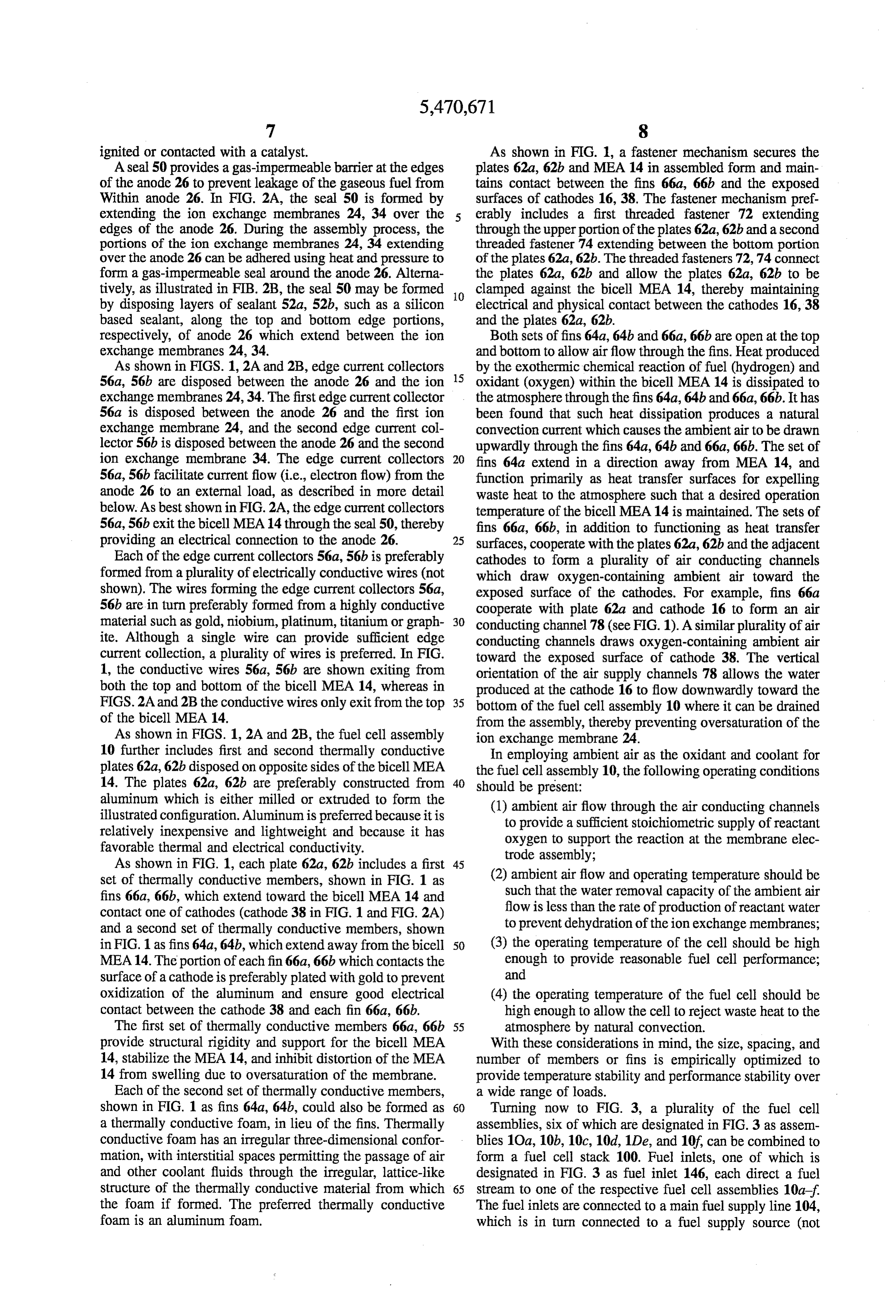
ignited or contacted with a catalyst. As shown in FIG. 1, a fastener mechanism secures the A seal 50 provides a gas-impermeable barrier at the edges plates 62a, 62b and MEA 14 in assembled form and main of the anode 26 to prevent leakage of the gaseous fuel from tains contact between the fins 66a, 66b and the exposed Within anode 26. In FIG. 2A, the seal 50 is formed by surfaces of cathodes 16, 38. The fastener mechanism pref extending the ion exchange membranes 24, 34 over the erably includes a first threaded fastener 72 extending edges of the anode 26. During the assembly process, the through the upper portion of the plates 62a, 62b and a second portions of the ion exchange membranes 24, 34 extending threaded fastener 74 extending between the bottom portion over the anode 26 can be adhered using heat and pressure to of the plates 62a, 62b. The threaded fasteners 72, 74 connect form a gas-impermeable seal around the anode 26. Alterna the plates 62a, 62b and allow the plates 62a, 62b to be tively, as illustrated in FIB. 2B, the seal 50 may be formed clamped against the bicell MEA 14, thereby maintaining by disposing layers of sealant 52a, 52b, such as a silicon O electrical and physical contact between the cathodes 16,38 based sealant, along the top and bottom edge portions, and the plates 62a, 62b.
respectively, of anode 26 which extend between the ion Both sets offins 64a, 64b and 66a, 66b are open at the top exchange membranes 24, 34. and bottom to allow airflow through the fins. Heat produced As shown in FIGS. 1, 2A and 2B, edge current collectors by the exothermic chemical reaction of fuel (hydrogen) and 56a, 56b are disposed between the anode 26 and the ion 15 oxidant (oxygen) within the bicell MEA 14 is dissipated to exchange membranes 24, 34. The first edge current collector the atmosphere through the fins 64a, 64b and 66a, 66b. It has 56a is disposed between the anode 26 and the first ion been found that such heat dissipation produces a natural exchange membrane 24, and the second edge current col convection current which causes the ambient air to be drawn lector 56b is disposed between the anode 26 and the second upwardly through the fins 64a, 64b and 66a, 66b. The set of ion exchange membrane 34. The edge current collectors 20 fins 64a extend in a direction away from MEA 14, and 56a, 56b facilitate current flow (i.e., electron flow) from the function primarily as heat transfer surfaces for expelling anode 26 to an external load, as described in more detail waste heat to the atmosphere such that a desired operation below. As best shown in FIG. 2A, the edge current collectors temperature of the bicell MEA 14 is maintained. The sets of 56a, 56b exit the bicell MEA14 through the seal 50, thereby fins 66a, 66b, in addition to functioning as heat transfer providing an electrical connection to the anode 26. 25 surfaces, cooperate with the plates 62a, 62b and the adjacent Each of the edge current collectors 56a, 56b is preferably cathodes to form a plurality of air conducting channels formed from a plurality of electrically conductive wires (not which draw oxygen-containing ambient air toward the shown). The wires forming the edge current collectors 56a, exposed surface of the cathodes. For example, fins 66a 56b are in turn preferably formed from a highly conductive cooperate with plate 62a and cathode 16 to form an air material such as gold, niobium, platinum, titanium or graph 30 conducting channel 78 (see FIG. 1). A similar plurality of air ite. Although a single wire can provide sufficient edge conducting channels draws oxygen-containing ambient air current collection, a plurality of wires is preferred. In FIG. toward the exposed surface of cathode 38. The vertical 1, the conductive wires 56a, 56b are shown exiting from orientation of the air supply channels 78 allows the water both the top and bottom of the bicell MEA 14, whereas in produced at the cathode 16 to flow downwardly toward the FIGS. 2A and 2B the conductive wires only exit from the top 35 bottom of the fuel cell assembly 10 where it can be drained of the bicell MEA 14. from the assembly, thereby preventing oversaturation of the As shown in FIGS. 1, 2A and 2B, the fuel cell assembly ion exchange membrane 24.
10 further includes first and second thermally conductive In employing ambient air as the oxidant and coolant for plates 62a, 62b disposed on opposite sides of the bicell MEA the fuel cell assembly 10, the following operating conditions 14. The plates 62a, 62b are preferably constructed from 40 should be present:
aluminum which is either milled or extruded to form the illustrated configuration. Aluminum is preferred because it is (1) ambient air flow through the air conducting channels relatively inexpensive and lightweight and because it has to provide a sufficient stoichiometric supply of reactant favorable thermal and electrical conductivity. oxygen to support the reaction at the membrane elec trode assembly;
As shown in FIG. 1, each plate 62a, 62b includes a first 45 set of thermally conductive members, shown in FIG. 1 as (2) ambient air flow and operating temperature should be fins 66a, 66b, which extend toward the bicell MEA 14 and such that the water removal capacity of the ambient air contact one of cathodes (cathode 38 in FIG. 1 and FIG. 2A) flow is less than the rate of production of reactant water and a second set of thermally conductive members, shown to prevent dehydration of the ion exchange membranes; in FIG. 1 as fins 64a, 64b, which extend away from the bicell 50 (3) the operating temperature of the cell should be high MEA14. The portion of each fin 66a, 66b which contacts the enough to provide reasonable fuel cell performance; surface of a cathode is preferably plated with gold to prevent and oxidization of the aluminum and ensure good electrical (4) the operating temperature of the fuel cell should be contact between the cathode 38 and each fin 66a, 66b. high enough to allow the cell to reject waste heat to the The first set of thermally conductive members 66a, 66b 55 atmosphere by natural convection. provide structural rigidity and support for the bicell MEA With these considerations in mind, the size, spacing, and 14, stabilize the MEA 14, and inhibit distortion of the MEA number of members or fins is empirically optimized to 14 from swelling due to oversaturation of the membrane. provide temperature stability and performance stability over Each of the second set of thermally conductive members, a wide range of loads.
shown in FIG. 1 as fins 64a, 64b, could also be formed as 60 Turning now to FIG. 3, a plurality of the fuel cell a thermally conductive foam, in lieu of the fins. Thermally assemblies, six of which are designated in FIG.3 as assem conductive foam has an irregular three-dimensional confor blies 10a, 10b, 10c, 10d, 1 De, and 10f, can be combined to mation, with interstitial spaces permitting the passage of air form a fuel cell stack 100. Fuel inlets, one of which is and other coolant fluids through the irregular, lattice-like designated in FIG. 3 as fuel inlet 146, each direct a fuel structure of the thermally conductive material from which 65 stream to one of the respective fuel cell assemblies 10a-f the foam if formed. The preferred thermally conductive The fuel inlets are connected to a main fuel supply line 104, foam is an aluminum foam. which is in turn connected to a fuel supply source (not
Page 14
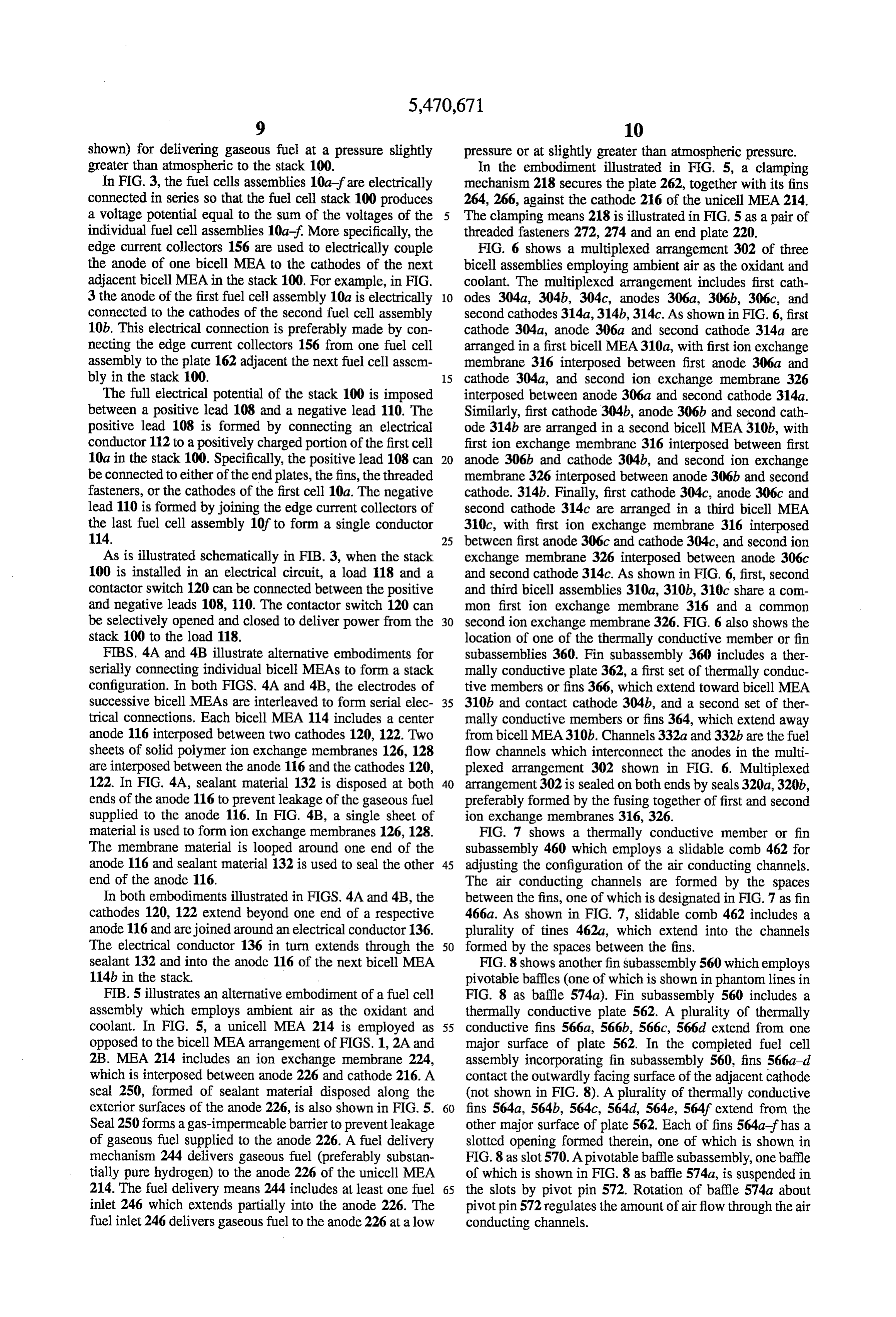
shown) for delivering gaseous fuel at a pressure slightly pressure or at slightly greater than atmospheric pressure. greater than atmospheric to the stack 100. In the embodiment illustrated in FIG. 5, a clamping In FIG. 3, the fuel cells assemblies 10a-fare electrically mechanism 218 secures the plate 262, together with its fins connected in series so that the fuel cell stack 100 produces 264, 266, against the cathode 216 of the unicell MEA 214. a voltage potential equal to the sum of the voltages of the The clamping means 218 is illustrated in FIG. 5 as a pair of individual fuel cell assemblies 10a-f. More specifically, the threaded fasteners 272, 274 and an end plate 220. edge current collectors 156 are used to electrically couple FIG. 6 shows a multiplexed arrangement 302 of three the anode of one bicell MEA to the cathodes of the next bicell assemblies employing ambient air as the oxidant and adjacent bicell MEA in the stack 100. For example, in FIG. coolant. The multiplexed arrangement includes first cath 3 the anode of the first fuel cell assembly 10a is electrically 10 odes 304a, 304b, 304c, anodes 306a, 306b, 306c, and connected to the cathodes of the second fuel cell assembly second cathodes 314a, 314b, 314c. As shown in FIG. 6, first 10b. This electrical connection is preferably made by con cathode 304a, anode 306a and second cathode 314a are necting the edge current collectors 156 from one fuel cell arranged in a first bicell MEA310a, with first ion exchange assembly to the plate 162 adjacent the next fuel cell assem membrane 316 interposed between first anode 306a and bly in the stack 100. 15 cathode 304a, and second ion exchange membrane 326 The full electrical potential of the stack 100 is imposed interposed between anode 306a and second cathode 314a. between a positive lead 108 and a negative lead 110. The Similarly, first cathode 304b, anode 306b and second cath positive lead 108 is formed by connecting an electrical ode 314b are arranged in a second bicell MEA 310b, with conductor 112 to a positively charged portion of the first cell first ion exchange membrane 316 interposed between first 10a in the stack 100. Specifically, the positive lead 108 can 20 anode 306b and cathode 304b, and second ion exchange be connected to either of the end plates, the fins, the threaded membrane 326 interposed between anode 306b and second fasteners, or the cathodes of the first cell 10a. The negative cathode. 314b. Finally, first cathode 304c, anode 306c and lead 110 is formed by joining the edge current collectors of second cathode 314c are arranged in a third bicell MEA the last fuel cell assembly 10fto form a single conductor 310c, with first ion exchange membrane 316 interposed 114. 25 between first anode 306c and cathode 304c, and second ion As is illustrated schematically in FIB. 3, when the stack exchange membrane 326 interposed between anode 306c 100 is installed in an electrical circuit, a load 118 and a and second cathode 314c. As shown in FIG. 6, first, second contactor switch 120 can be connected between the positive and third bicell assemblies 310a, 310b, 30c share a com and negative leads 108, 110. The contactor switch 120 can mon first ion exchange membrane 316 and a common be selectively opened and closed to deliverpower from the 30 second ion exchange membrane 326. FIG. 6 also shows the stack 100 to the load 118. location of one of the thermally conductive member or fin FIBS. 4A and 4B illustrate alternative embodiments for subassemblies 360, Fin subassembly 360 includes a ther serially connecting individual bicell MEAs to form a stack mally conductive plate 362, a first set of thermally conduc configuration. In both FIGS. 4A and 4B, the electrodes of tive members or fins 366, which extend toward bicell MEA successive bicell MEAs are interleaved to form serial elec 35 310b and contact cathode 304b, and a second set of ther trical connections. Each bicell MEA 114 includes a center mally conductive members or fins 364, which extend away anode 116 interposed between two cathodes 120, 122. Two from bicell MEA310b. Channels 332a and 332b are the fuel sheets of solid polymer ion exchange membranes 126, 128 flow channels which interconnect the anodes in the multi are interposed between the anode 116 and the cathodes 120, plexed arrangement 302 shown in FIG. 6. Multiplexed 122. In FIG. 4A, sealant material 132 is disposed at both 40 arrangement 302 is sealed on both ends by seals 320a,320b, ends of the anode 116 to prevent leakage of the gaseous fuel preferably formed by the fusing together of first and second supplied to the anode 116. In FIG. 4B, a single sheet of ion exchange membranes 316, 326.
material is used to form ion exchange membranes 126, 128. FIG. 7 shows a thermally conductive member or fin The membrane material is looped around one end of the subassembly 460 which employs a slidable comb 462 for anode 116 and sealant material 132 is used to seal the other 45 adjusting the configuration of the air conducting channels. end of the anode 116. The air conducting channels are formed by the spaces In both embodiments illustrated in FIGS. 4A and 4B, the between the fins, one of which is designated in FIG.7 as fin cathodes 120, 122 extend beyond one end of a respective 466a. As shown in FIG. 7, slidable comb 462 includes a anode 116 and are joined around an electrical conductor 136. plurality of tines 462a, which extend into the channels The electrical conductor 136 in turn extends through the 50 formed by the spaces between the fins. sealant 132 and into the anode 116 of the next bicell MEA FIG.8 shows another fin subassembly 560 which employs 114b in the stack. pivotable baffles (one of which is shown in phantom lines in FIB. 5 illustrates an alternative embodiment of a fuel cell FIG. 8 as baffle 574a). Fin subassembly 560 includes a assembly which employs ambient air as the oxidant and thermally conductive plate 562. A plurality of thermally coolant. In FIG. 5, a unicell MEA 214 is employed as 55 conductive fins 566a, 566b, 566c, 566d extend from one opposed to the bicell MEA arrangement of FIGS. 1, 2A and major surface of plate 562. In the completed fuel cell 2B. MEA 214 includes an ion exchange membrane 224, assembly incorporating fin subassembly 560, fins 566a-d which is interposed between anode 226 and cathode 216. A contact the outwardly facing surface of the adjacent cathode seal 250, formed of sealant material disposed along the (not shown in FIG. 8). A plurality of thermally conductive exterior surfaces of the anode 226, is also shown in FIG.S. 60 fins 564a, 564b, 564c, 564d, 564e, 564f extend from the Seal 250 forms a gas-impermeable barrier to prevent leakage other major surface of plate 562. Each of fins 564af has a of gaseous fuel supplied to the anode 226. A fuel delivery slotted opening formed therein, one of which is shown in mechanism 244 delivers gaseous fuel (preferably substan FIG.8 as slot 570. A pivotable baffle subassembly, one baffle tially pure hydrogen) to the anode 226 of the unicell MEA of which is shown in FIG. 8 as baffle 574a, is suspended in 214. The fuel delivery means 244 includes at least one fuel 65 the slots by pivot pin 572. Rotation of baffle 574a about inlet 246 which extends partially into the anode 226. The pivot pin 572 regulates the amount of airflow through the air fuel inlet 246 delivers gaseous fuel to the anode 226 at a low conducting channels.
Page 15
Arrows Ain FIG. 8 show the direction of airflow through inert metal is gold.
the channels formed between fins 566a-d, and represent the 5. The electrochemical fuel cell assembly of claim 1, air supply for the electrochemical reaction at the adjacent wherein said electrical connection means comprises electri cathode (not shown). Arrow B in FIG. 8 shows the direction cal conductors disposed between said anode and said ion of airflow through the channels formed between fins 564af, 5 exchange membrane, said electrical conductors extending and represents the air supply for conducting heat from the through said sealing means.
adjacent fuel cell structure (not shown), thereby providing 6. The electrochemical fuel cell of claim 5, wherein said thermal management to the adjacent fuel cell structure. electrical conductors are formed from gold wire. FIG. 9 shows pivotable baffle subassembly 574 for use in 7. The electrochemical fuel cell assembly of claim 1, conjunction with the fin subassembly 560 in FIG. 8. Sub 10 wherein said plate has a thermally conductive material assembly 574 includes a plurality of baffles 574a, 574b, extending from another major surface thereof, whereby heat 574c mounted on central pivot pin 572. FIG. 10 shows a side generated exothermically in said membrane electrode view of pivotable baffle subassembly 574. assembly is further dissipated to the atmosphere through FIG. 11 shows schematically an electrochemical fuel cell said material.
assembly employing ambient air as the oxidant and coolant, 15 8. The electrochemical fuel cell assembly of claim 7, which employs external dampers 676,678 having pivotable wherein said material comprises a plurality of thermally baffles 674, 684, respectively, for adjusting the flow through conductive members.
the air conducting channels 664, 666. In FIG. 11, anode 626, 9. The electrochemical fuel cell assembly of claim 7, ion exchange membrane 624 and cathode 616 form the wherein said material comprises a thermally conductive membrane electrode assembly. Fins (not shown) extend 20 foam.
from each major surface of plate 662. The spaces formed 10. The electrochemical fuel cell assembly of claim 9, between the extending fins form air conducting channels wherein said thermally conductive foam is an aluminum 664, 666. Dampers 676,678 include baffles 674, 684, which foam.
are mounted on pivot pins 672, 682, respectively. Rotation 11. The electrochemical fuel cell assembly of claim 1, of baffle 674, 684 about the respective pivot pins 672, 682 25 wherein said fuel delivery means comprises a fuel inlet and regulates the amount of air flow through the air conducting a fuel outlet, said fuel outlet directing unreacted components channels 664, 666. of said gaseous fuel stream away from said anode. While particular elements, embodiments and applications 12. The electrochemical fuel cell assembly of claim 1, of the present invention have been shown and described, it further comprising a fan for directing said ambient air onto will be understood, of course, that the invention is not 30 the exposed surface of said porous electrically conductive limited thereto since modifications may be made by those cathode.
skilled in the art, particularly in light of the foregoing 13. The electrochemical fuel cell assembly of claim 1, teachings. It is therefore contemplated by the appended wherein said gaseous fuel stream comprises hydrogen, said claims to cover such modifications as incorporate those assembly further comprising means for accumulating water features which come within the spirit and scope of the 35 condensed on said first members.
invention.
What is claimed is: 14. A fuel cell stack comprising: 1. An electrochemical fuel cell assembly comprising: a plurality of fuel cell assemblies as defined in claim 1; a membrane electrode assembly comprising a porous serial connection means for electrically connecting said electrically conductive anode, a porous electrically 40 plurality of fuel cell assemblies in an electrical series conductive cathode having a surface thereof exposed to having a first assembly and a last assembly, wherein the ambient air, and an ion exchange membrane interposed anode of each assembly except the last assembly in said between said anode and said cathode, series is electrically connected to the cathode of the next adjacent assembly in said series;
sealant means for forming a gas-impermeable barrier a positive current lead electrically connected to the cath
ode of said first assembly in said series; and fuel delivery means for supplying a gaseous fuel stream to a negative current lead electrically connected to the anode said anode; of the last assembly in said series. electrical connection means for providing an electrical 15. The fuel cell stack of claim 14, wherein said plurality connection to said anode and to said cathode, of fuel cell assemblies share a common ion exchange 50 membrane.
a thermally conductive plate having a plurality of first 16. An electrochemical fuel cell assembly comprising: thermally conductive members extending from a major surface thereof, said first members contacting portions a bicell membrane electrode assembly comprising a first of said exposed cathode surface, adjacent ones of said porous electrically conductive cathode having a surface first members cooperating with said plate and said 55 thereof exposed to ambient air, a porous electrically exposed cathode surface to form at least one air con conductive anode, a second porous electrically conduc ducting channel; tive cathode having a surface thereof exposed to ambi whereby at least a portion of the heat generated exother ent air, a first ion exchange membrane interposed between said first cathode and said anode, and a second mically in said membrane electrode assembly is dissi ion exchange membrane interposed between said sec pated to the atmosphere through said first members. 60 ond cathode and said anode, 2. The electrochemical fuel cell of claim 1, wherein said sealing means for forming a gas-impermeable barrier plate is formed as a single planar piece.
3. The electrochemical fuel cell of claim 1, wherein said around said anode, plate and said first members are formed of aluminum, the fuel delivery means for delivering gaseous fuel to said portions of said first members contacting said cathode 65 anode, surface having an inert metal applied thereto. electrical connection means for providing an electrical 4. The electrochemical fuel cell of claim 3, wherein said connection to said anode, to said cathode, and to said
Page 16
second cathode; through said first and second material. a first thermally conductive plate having a plurality of first 22. The electrochemical fuel cell assembly of claim 21, thermally conductive members extending from a major wherein said first and second material each comprises a surface thereof, said first members contacting portions plurality of thermally conductive members. of said exposed first cathode surface, adjacent ones of 23. The electrochemical fuel cell assembly of said first members cooperating with said first plate and claim 21, wherein said material comprises a thermally said exposed first cathode surface to form at least one conductive foam.
air conducting channel; 24. The electrochemical fuel cell assembly of claim 23, wherein said thermally conductive foam is an aluminum a second thermally conductive plate having a plurality of 10 foam, second thermally conductive members extending from 25. The fuel cell assembly as in claim 16, wherein said a major surface thereof, said second members contact sealing means comprises said first and second membranes, ing portions of said exposed second cathode surface, the edges of the first and second membranes bonded together adjacent ones of said second members cooperating with said second plate and said exposed second cathode 15 to 26. form a gas-impermeable barrier around said anode. The electrochemical fuel cell assembly of claim 16, surface to form at least one air conducting channel; wherein said fuel delivery means comprises a fuel inlet and whereby at least a portion of the heat generated exother afuel outlet, said fuel outlet directing unreacted components mically in said membrane electrode assembly is dissi of said gaseous fuel stream away from said anode. pated to the atmosphere through said first and second 27. The electrochemical fuel cell assembly of claim 16, members. 20 further comprising a fan for directing said ambient air onto 17. The electrochemical fuel cell of claim 16, wherein the exposed surface of said porous electrically conductive said plate and said first and second members are formed of cathode.
aluminum, the portions of said first and second members 28. The electrochemical fuel cell assembly of claim 16, contacting said cathode surface having an inert metal wherein said gaseous fuel stream comprises hydrogen, said applied thereto. 25 assembly further comprising means for accumulating water 18. The electrochemical fuel cell of claim 17, wherein condensed on said first members.
said inert metal is gold. 29. A fuel cell stack comprising: 19. The electrochemical fuel cell assembly of claim 16, a plurality of fuel cell assemblies as defined in claim 16; wherein said electrical connection means comprises first electrical conductors disposed between said anode and said 30 serial connection means for electrically connecting said first membrane, and second electrical conductors disposed plurality of fuel cell assemblies in an electrical series between said anode and said second membrane, said first having a first assembly and a last assembly, wherein the and second electrical conductors extending through said anode of each assembly except the last assembly in said sealing means. series is electrically connected to the cathodes of the 20. The electrochemical fuel cell of claim 19, wherein 35 next adjacent assembly in said series; said first and second electrical conductors are formed from a positive current lead electrically connected to the cath gold wire. odes of said first assembly in said series; and 21. The electrochemical fuel cell assembly of claim 16, a negative current lead electrically connected to the anode wherein said first plate has a first thermally conductive of the last assembly in said series. material extending from another major surface thereof and 40 30. The fuel cell stack of claim 29, wherein said plurality wherein said second plate has a second thermally conductive of fuel cell assemblies share a common first ion exchange material extending from another major surface thereof, membrane and a common second ion exchange membrane. whereby heat generated exothermically in said membrane electrode assembly is further dissipated to the atmosphere
Provenance
- Collection
- Cited prior art
- Original PDF
- patentimages.storage.googleapis.com →
- Filed
- 1993-12-22
- Pages
- 16
- Method
- pdftotext (the PDF's own text layer) + pdftoppm 300dpi page scans
- Source
- Google Patents bibliographic record
- Granted
- 1995-11-28
- Inventors
- Nicholas J. Fletcher; Gordon J. Lamont; Vesna Basura; Henry H. Voss; David P. Wilkinson; Ballard Power Systems Inc
- Transcribed from
- patentimages.storage.googleapis.com →