patent · US5318863
Near ambient, unhumidified solid polymer fuel cell
7 June 1994
Page 1 — bibliographic record
United States Patent (19) 11 Patent Number: 5,318,863
Dhar 45) Date of Patent: Jun. 7, 1994 54 NEAR AMBENT, UNHUMIDIFIED SOLID OTHER PUBLICATIONS POLYMERFUEL CELL K. B. Prater, The Renaissance of the Solid Polymer (75) Inventor: Hari P. Dhar, College Station, Tex. El; Journal of Power Sources, 29 (1991), pp. (73) Assignee: BCS Technology, Inc., Bryan, Tex. K. B. Prater, Solid Polymer Fuel Cell Developments at (*) Notice: . The portion of the term of this patent Ballard, Journal of Power Sources, 37 (1992), pp.
disclaimed. (List continued on next page.)
22 Filed: Feb. 26, 1993 Primary Examiner-Stephen Kalafut Attorney, Agent, or Firm-Pravel, Hewitt, Kimball &
Related U.S. Application Data Krieger 63 Continuation-in-part of Ser. No. 809,581, Dec. 17, 57 ABSTRACT 1991, Pat. No. 5,242,764. - o
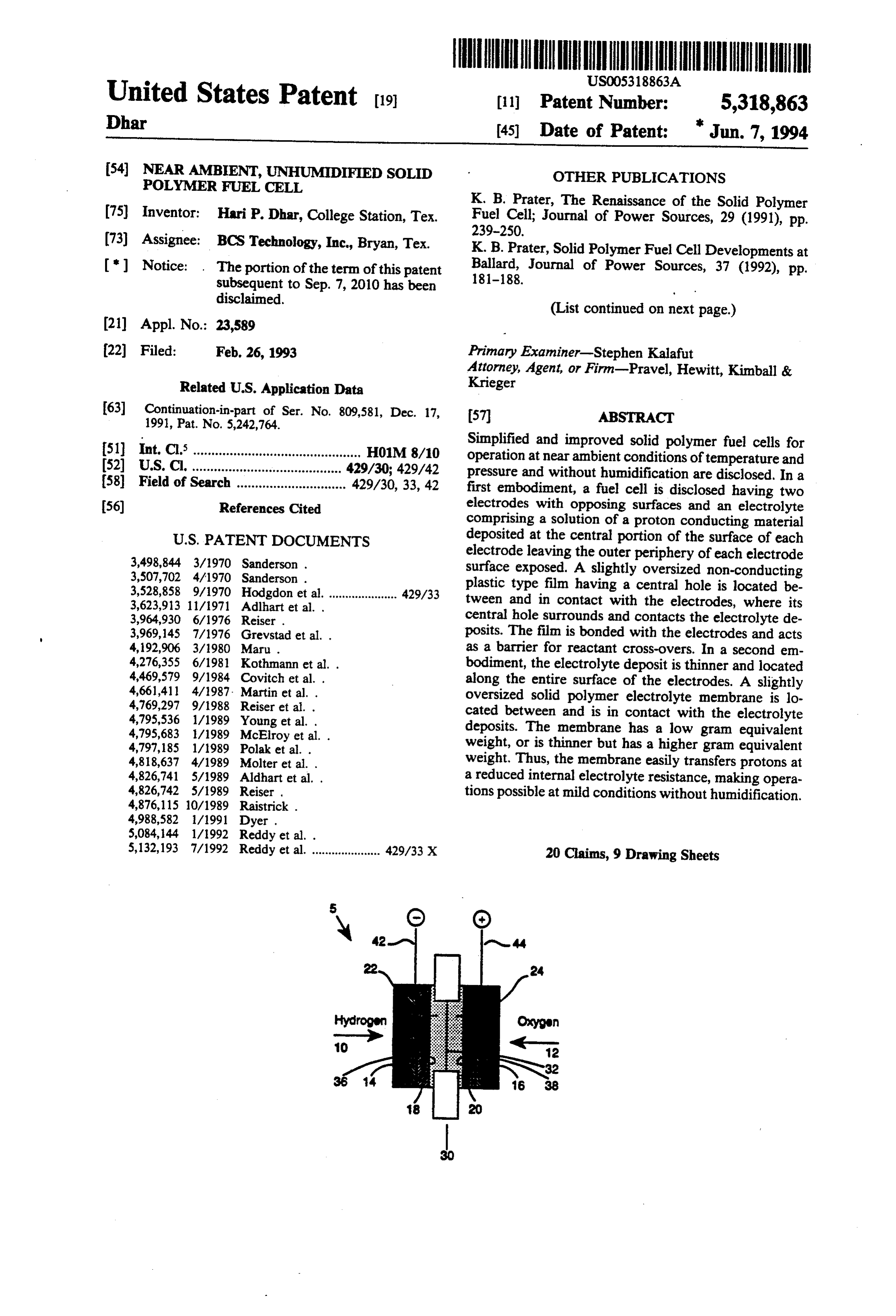
Simplified and improved solid polymer fuel cells for 51) int. Cl. .............................................. H01M 8/10 operation at near ambient conditions of temperature and (52) ... 429/30; 429/42 pressure and without humidification are disclosed. In a 58) Field of Search .............................. 429/30, 33, 42 first embodiment, a fuel cell is disclosed having two 56) References Cited electrodes with opposing surfaces and an electrolyte comprising a solution of a proton conducting material
electrode leaving the outer periphery of each electrode 3,507,702 4/1970 Sanderson . surface exposed. A slightly oversized non-conducting 3,528,858 9/1970 Hodgdon et al. ..................... 429/33 plastic type film having a central hole is located be 3,623,913 11/1971 Adlhart et al. . tween and in contact with the electrodes, where its 3,964,930 6/1976 Reiser . central hole surrounds and contacts the electrolyte de 3,969,145 7/1976 Grevstad et al. . posits. The film is bonded with the electrodes and acts 4,192,906 3/1980 Maru . as a barrier for reactant cross-overs. In a second en 4,276,355 6/1981 Kothmann et al. . bodiment, the electrolyte deposit is thinner and located 4,469,579 9/1984 Covitch et al. . along the entire surface of the electrodes. A slightly 4,661,411 4/1987. Martin et al. . oversized solid polymer electrolyte membrane is lo 4,769,297 9/1988 Reiser et al. . cated between and is in contact with the electrolyte 4,795,536 1/1989 Young et al. . deposits. The membrane has a low gram equivalent
4,797,185 1/1989 Polak et al. . weight, or is thinner but has a higher gram equivalent 4,818,637 4/1989 Molter et al. . weight. Thus, the membrane easily transfers protons at 4,826,741 5/1989 Aldhart et al. . a reduced internal electrolyte resistance, making opera 4,826,742 5/1989 Reiser . tions possible at mild conditions without humidification.
5,132, 193 7/1992 Reddy et al. ..................... 429/33 X 20 Claims, 9 Drawing Sheets
Page 2
OTHER PUBLICATIONS S. Srinivasan, et al., "Advances in Solid Polymer Elec R. Moore and C. Martin, "Morphology and Chemical trolyte Fuel Cell Technology with Low Platinum Properties of the Dow Perfluorosulfonate Ionomers,' Loading Electrodes,” J. Power Sources vol. 22, p. 359 Macromolecules, vol. 22, No. 9, p. 3594 (1989). (1988).
E. Ticianelli, et al., "Methods to Advance Technology D. Watkins, et al., "Canadian Solid Polymer Fuel Cell of Proton Exchange Membrane Fuel Cells,” J. Electro Development," 32nd International Power Sources chemical Soc, vol. 135, No. 9, p. 2209 (Sep. 1988). Symposium, Jun. 9-12, 1986, The Electrochemical So E. Ticianelli, et al., "Localization of Platinum in Low ciety, Pennington, New Jersey, p. 782. Catalyst Loading Electrodes to Attain High Power K. Prater, “The Solid Polymer Fuel Cell-A Viable Densities in SPE Fuel Cells,” J. Electroanalytical Product Today," Proceedings of the 4th Canadian Hy Chem, vol. 251, p. 275 (1988). drogen Workshop, Nov. 1-2, 1989, Canadian Hydrogen Association, Ottawa, Canada.

Page 3
Drawing sheet — no readable text.
Page 4
Drawing sheet — no readable text.
Page 5
Drawing sheet — no readable text.
Page 6
Drawing sheet — no readable text.
Page 7
Drawing sheet — no readable text.
Page 8
Drawing sheet — no readable text.
Page 9
Drawing sheet — no readable text.
Page 10
Drawing sheet — no readable text.
Page 11
Drawing sheet — no readable text.
Page 12
with manifolds to the electrodes, and cooling is pro
NEAR AMBIENT, UNHUMIDIFIED SOLID vided either by the reactants or by a cooling medium. POLYMERFUEL CELL Also within the stack are current collectors, cell-to-cell seals, insulations, piping, and instrumentation. The
This is a continuation-in-part of co-pending applica 5 stack, housing, and associated hardware make up the tion Ser. No. 809,581, filed Dec. 17, 1991, which issued fuel cell module.
on Sept. 7, 1993 as U.S. Pat. No. 5,242,764 to Dhar, and Fuel cells may be classified by the type of electrolyte, of which benefit is claimed under Title 35 U.S. C. S 120. i.e., liquid or solid that they contain. A fuel cell using a BACKGROUND OF THE INVENTION solid electrolyte, such as a solid polymer referred to as O a proton exchange membrane, operates best when the 1. Field of the Invention
The present invention relates to improvements of electrolyte membrane is kept moist with water because solid polymer fuel cells, otherwise referred to as solid The membranewill the membrane not operate efficiently when it is dry.
polymer electrolyte or proton exchange membrane fuel operation of the fuel cell,constant requires humidification during cells, where these cells are operable at near ambient 15 the reactant gases, usually hydrogenbyand normally adding water to conditions of temperature and pressure and do not re pass by the membrane on each side ofoxygen, the mem that quire external humidification. brane/electrodes assembly. The accessories required 2. Description of Related Art
Fuel cells are typically used as a source of primary for humidification add instrumentation and hence power in remote areas where the usual sources of power 20 weight to the fuel cell.
are unavailable and where service and maintenance of The proton exchange membrane used in a solid poly equipment is limited. Fuel cells may also be used as an mer fuel cell acts as the electrolyte as well as a barrier alternative power source in earth and space applica for preventing the mixing of the reactant gases. An tions. Examples in this area are unattended communica example of a suitable membrane is a copolymeric per tions repeaters, navigational aids, space flights and 25 fluorocarbon material containing a basic unit of fluori weather and oceanographic stations. For such applica nated carbon chain and a sulphonic acid group. There tions, the power system must be self-contained and the may be variations in the molecular configurations of this reliability of the system is of maximum importance. membrane. One membrane commonly used as a fuel cell Generally, a fuel cell is a device which converts the solid electrolyte is a well known perfluorocarbon mate energy of a chemical reaction into electricity. It differs 30 rial sold by E. I. DuPont de Nemours under the trade from a battery in that the fuel and oxidant are stored mark "Nafion.' Dow Chemicals Company has also external to the cell, which can generate power as long developed proton exchange membranes that are still in as the fuel and oxidant are supplied. A fuel cell produces the experimental stage. Excellent performances are an electromotive force by bringing the fuel and oxidant obtained using these membranes if the fuel cells are into contact with two suitable electrodes and an electro 35 operated under fully hydrated, essentially water lyte. A fuel, such as hydrogen gas, for example, is intro saturated conditions. As such, the membrane must be duced at a first electrode where it reacts electrochemi continuously humidified.
cally in the presence of the electrolyte to produce elec In addition to the humidification problem, the mem trons and protons in the first electrode. The electrons brane contributes to the ohmic resistance within the cell are circulated from the first electrode to a second elec trode through an electrical circuit connected between itself and, in turn, lowers fuel cell performance. If the the electrodes. Protons pass through the electrolyte to fuel cell must perform at a lower temperature and pres the second electrode. Simultaneously, an oxidant, such tionsand sure if the reaction kinetics of the two halfcell reac shown above are slower, the use of less membrane as oxygen gas or air, is introduced to the second elec trode where the oxidant reacts electrochemically in 45 as the electrolyte becomes imperative. presence of the electrolyte consuming the electrons Cooling and humidification requirements increase the circulated through the electrical circuit and the protons cost and complexity of the fuel cell, reducing its use as at the second electrode. The first electrode may alterna an alternative energy supply in many applications. Ac tively be referred to as an oxidizing or as a fuel elec cordingly, there is a need for a fuel cell with no require trode, and the second electrode may alternatively be 50 ment for humidification which operates at near ambient referred to as an oxidant or as a reducing electrode. The conditions.
halfcell reactions at the two electrodes are, respec SUMMARY OF THE INVENTION tively, as follows:
A fuel cell according to the present invention is an 55 improvement upon solid polymer electrolyte fuel cells, where the solid electrolyte comprises a membrane hav ing a central hole so that the membrane does not need
The external electrical circuit withdraws electrical the humidification of the prior art, thus allowing for less current and thus receives electrical power from the cell. complicated
One and lighter modules.
embodiment of the invention provides a fuel cell
The overall fuel cell reaction produces electrical energy which is the sum of the separate halfcell reactions writ for generating electricity from a reaction between a fuel ten above. A byproduct of the reaction is formed as well source and an oxidant source, the fuel cell comprising: as some heat. a first porous gas diffusion electrode; a second porous In practice, fuel cells are not operated as single units; gas diffusion electrode, the second electrode defining an rather, they are connected in a series, stacked one on 65 electric field with the first electrode; a first electrolyte top of the other, or placed side by side. A series of fuel deposit placed on the first electrode; a second electro cells, referred to as a fuel cell stack, is normally en lyte deposit placed on the second electrode; and an closed in a housing. The fuel and oxidant are directed electrolyte membrane positioned between and in
Page 13
contact with the first and second electrolyte deposit, the a solution of a mixture of solid polymer electrolytes. membrane having a central hole. The amount of deposits should be sufficient to prevent According to a more specific embodiment, the first cross-overs of reactants when the electrodes are assen and second electrolyte deposit comprises a perfluoro bled in a fuel cell. The electrolyte is not applied around carbon copolymer proton conducting material. the periphery of the electrodes. Further, a non-conduct According to a further embodiment, the first and ing film is used as a gasket which bonds well with the second electrolyte deposit in the dry state comprises electrodes, the catalysts and the electrolyte deposits. about 10 to 20 mg per about 5 cm2 electrode area of The non-conducting film has the central part cut out, so about a 5% concentrated solution of Nafion. A 5% that when assembled with the two electrodes, the pro concentrated solution is defined as 5 grams of solid per 10 ton transfer occurs from the first to the second elec 100 ml of solvent. The solvent is preferably a lower trode. This approach provides several advantages, in aliphatic alcohol such as ethanol or isopropanol, or cluding a significant reduction in the amount of solid their mixtures. electrolyte material and the use of a significantly According to yet another embodiment of the inven cheaper gasket.
tion, the electrolyte membrane comprises a perfluoro 15 In another improved embodiment according to the carbon copolymer proton conducting material. present invention, a solid polymer electrolyte mem According to still a further embodiment of the inven brane without a central hole is placed between two gas tion, there is provided a fuel cell comprising: a fuel or diffusion electrodes, onto which a thin coating of a oxidizing electrode and an oxidant or reducing elec solution of a solid polymer electrolyte has been applied. trode; an electrolyte member between and in contact 20
The purpose of the thin coating is to increase the three with the fuel electrode and the oxidant electrode, the dimensional reaction zone of the platinum-on-carbon electrolyte member defining a first and second electro catalyst of the electrode. The solid polymer membrane lyte deposit on opposing surfaces of the electrodes; an should be sufficiently thin enough to keep itself moist electrolyte membrane sheet, having a central hole, posi with the water produced in the fuel cell reaction, so that tioned between and on the periphery of the deposits; a 25 it functions without external humidification. Or, the fuel distribution member in flow communication with the oxidizing electrode for supplying fuel thereto; and solid polymer membrane should have a low enough equivalent weight so that the membrane has inherently an oxidant distribution member in flow communication more protons per unit weight in its structure and thus with the reducing electrode for supplying an oxidant functions as a medium for proton transfer in the fuel cell thereto. The fuels are supplied in liquid form, or alterna 30 reaction. The gram equivalent weight of a substance is tively, in gaseous form. defined as the weight of a substance in units of grams A small amount of electrolyte deposit on an electrode which will react with one gram of hydrogen. allows for operation under much reduced ohmic resis lower the equivalent weight of a substance, Thus, the the more tance. In addition, the electrolyte deposit forms resilient protons it has per unit weight.
layer on the electrode surface. A reduced ohmic resis 35 tance compensates for the kinetic advantage that is BRIEF DESCRIPTION OF THE DRAWINGS obtainable for the above two halfcell reactions at a higher temperature and pressure. Thus, the fuel cell rated The accompanying drawings, which are incorpo operation becomes feasible at a lower temperature and the in and form a part of the specification, illustrate pressure. embodiments of the present invention, and, together The above conditions allow the electrolyte to retain with the description, serve to explain the principles of sufficient water that is formed by the electrochemical the invention. It is to be noted that the drawings illus trate only typical embodiments of the invention and are reaction during fuel cell operation allowing a continu therefore not be to considered limiting of its scope, for ous cell performance without membrane failure.
Experience with the fuel cells implemented as de 45 the invention will admit to other equally effective em scribed above has led to further understanding of the bodiments. In the drawings:
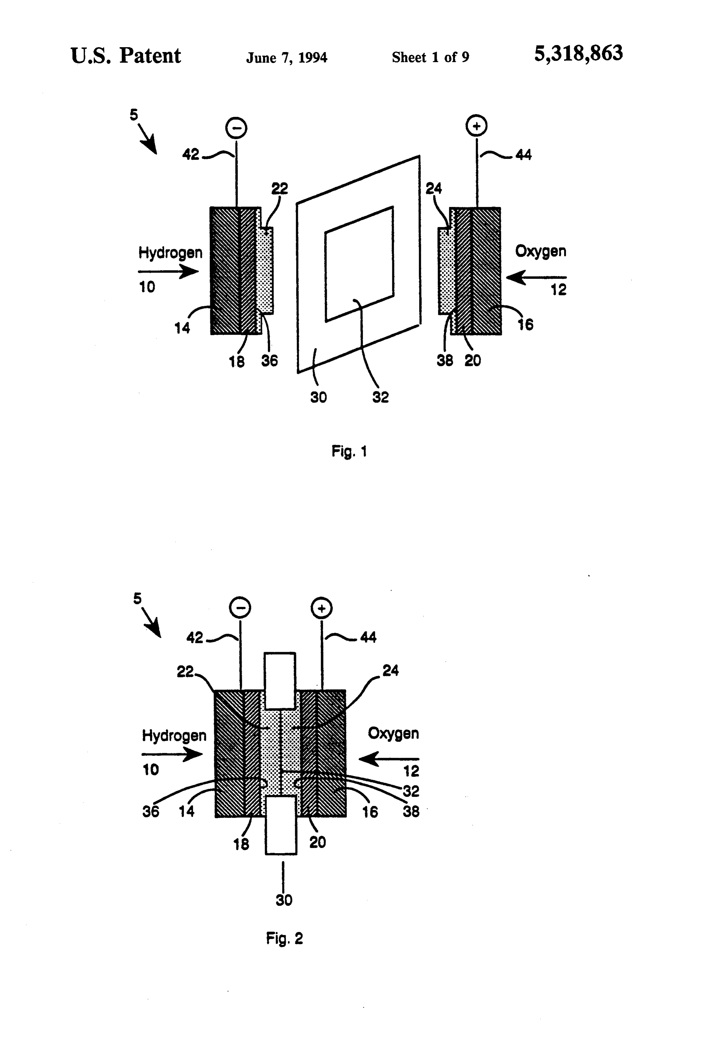
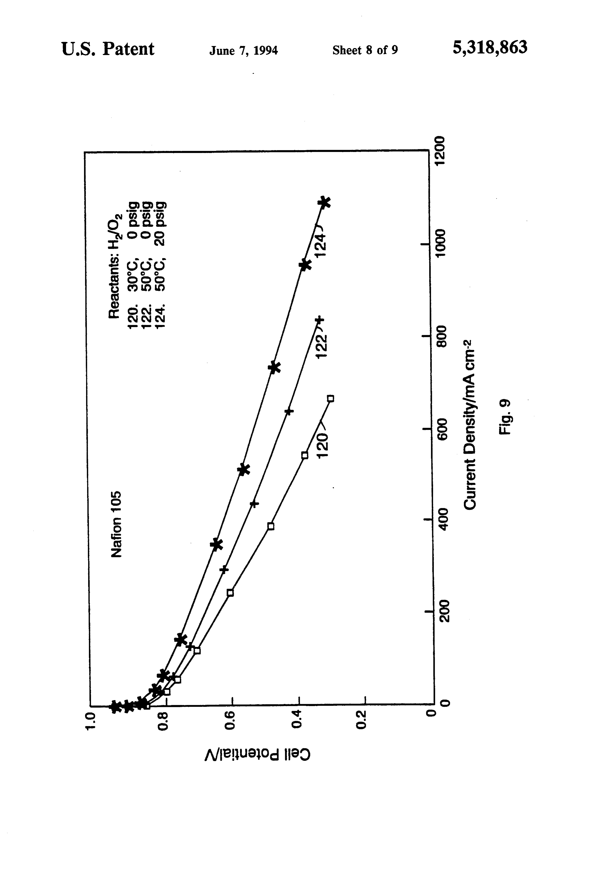
FIG. 1 is a schematic cross-section of an embodiment working principle of near ambient, unhumidified solid polymer fuel cells, and to further improvements and of the invention in which a fuel cell is provided having operating conditions for such fuel cells. Consequently, twoFIG. electrodes and a membrane with a central hole; 2 is a schematic cross-section of the membrane an improvement of the previous embodiments is 50 achieved by replacing the solid polymer membrane by a and electrodes assembly of FIG. 1;
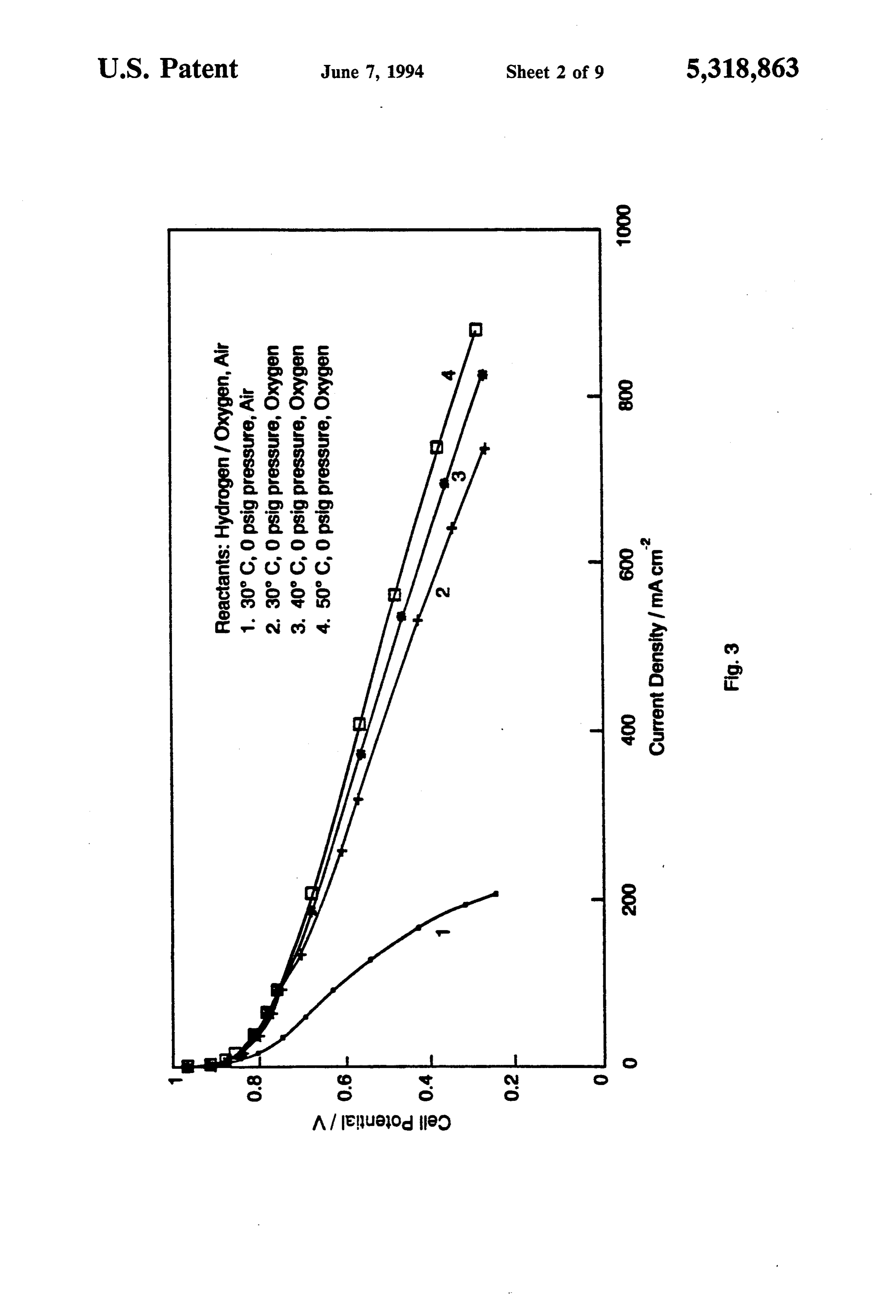
much cheaper plastic-type material, otherwise refer FIG. 3 is a graph of cell potential versus current enced to as a gasket. Furthermore, it was discovered density comparing a fuel cell at various temperatures that a continuous electrolyte membrane which has an and with various oxidants;
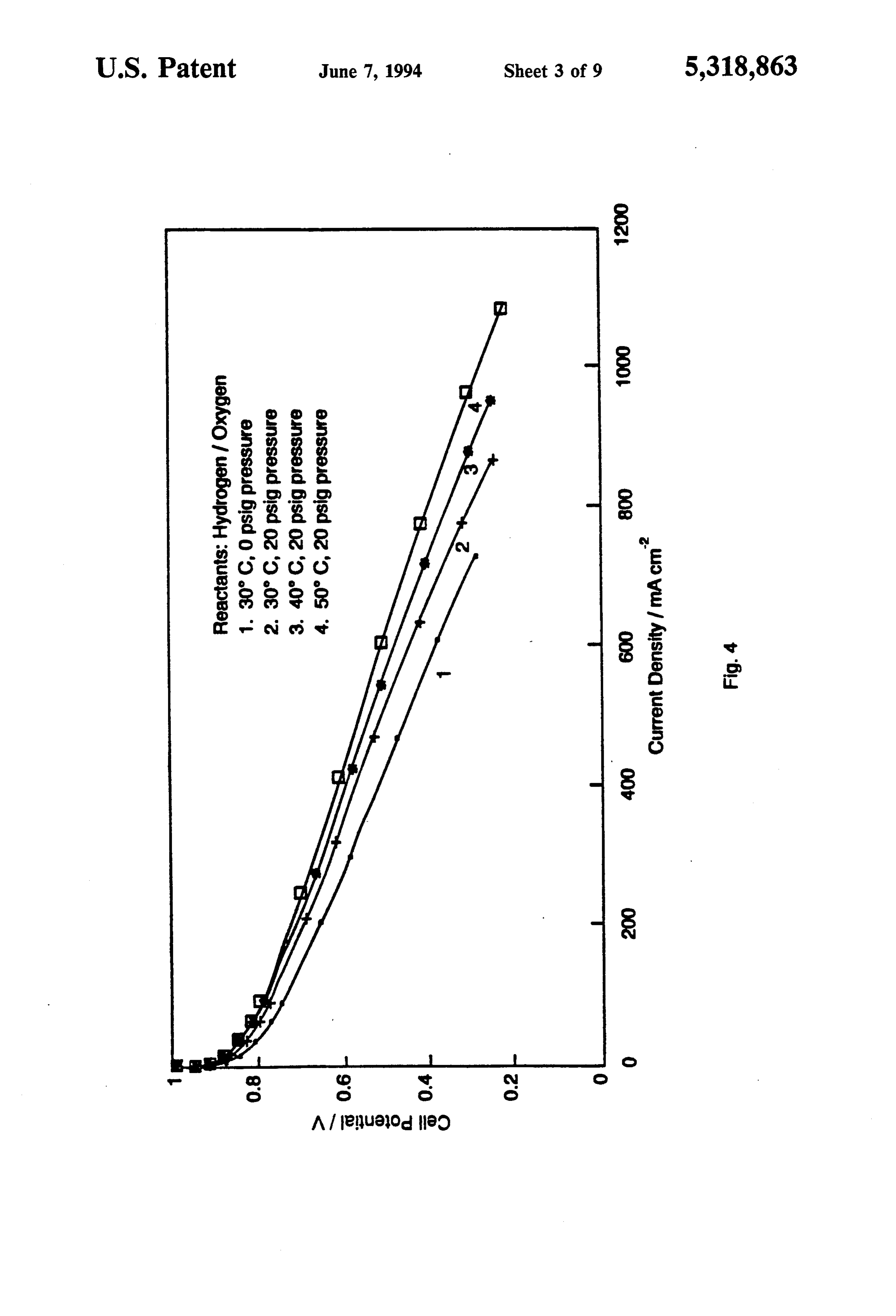
increased inherent ionic conductivity, that is, reduced 55 FIG. 4 is a graph of cell potential versus current ohmic resistivity, functions in a near ambient fuel cell density comparing a fuel cell at various temperatures with little or no electrolyte deposits on the electrodes. and pressures;
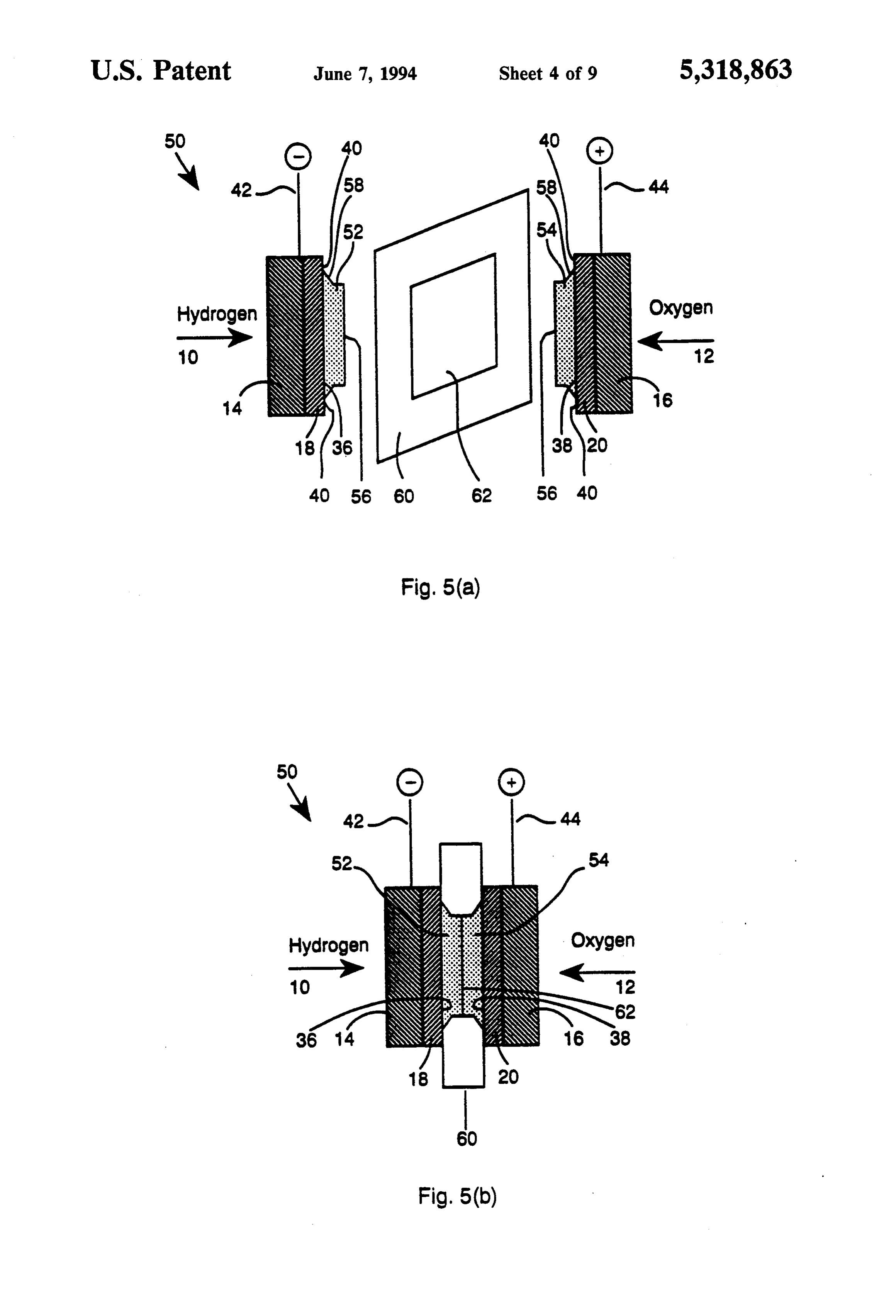
The fuel cell performs better than that with an electro FIG. 5(a) is a schematic cross-section of an alterna lyte having a lesser ionic conductivity if the electrolyte tive embodiment in which a fuel cell is provided having deposits have an increased ionic conductivity. Thus, two electrodes and a non-conducting gasketting mate improvements are achieved by using a continuous uncut rial with a central hole;
membrane without a central hole having an increased FIG. 5(b) is a side view of the fuel cell of FIG. 5(a) proton conductivity, or which is thin enough to present after being assembled;
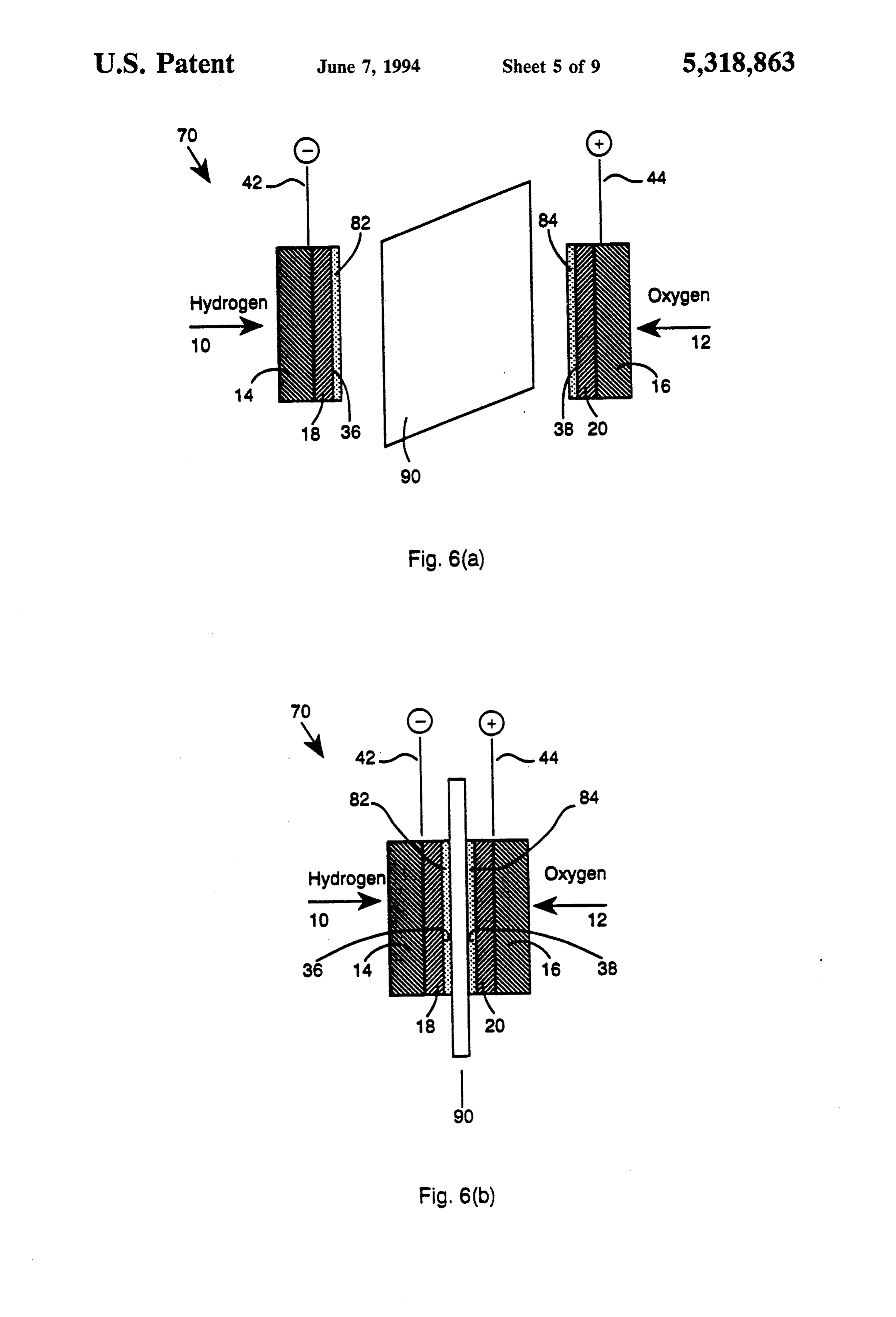
less resistivity to proton conduction. FIG. 6(a) is a schematic cross-section of another In one improved embodiment according to the pres 65 alternative embodiment of the invention in which a fuel ent invention, two fuel cell electrodes, having been cell is provided with having two electrodes and a con catalyzed by a mixture of platinum and carbon, are tinuous membrane that may be thin or thick, or that may coated with a solution of a solid polymer electrolyte or have a high or low equivalent weight;
Page 14
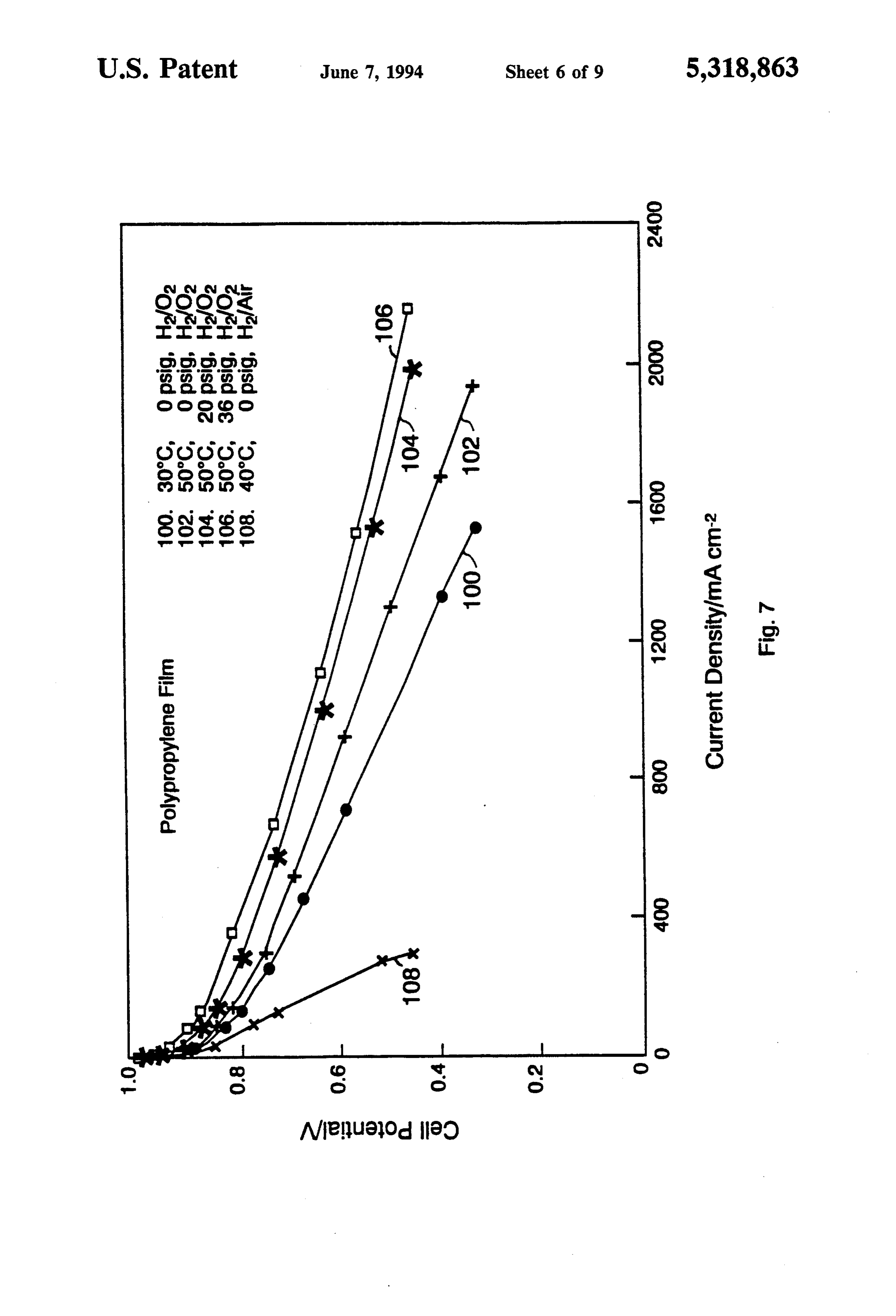
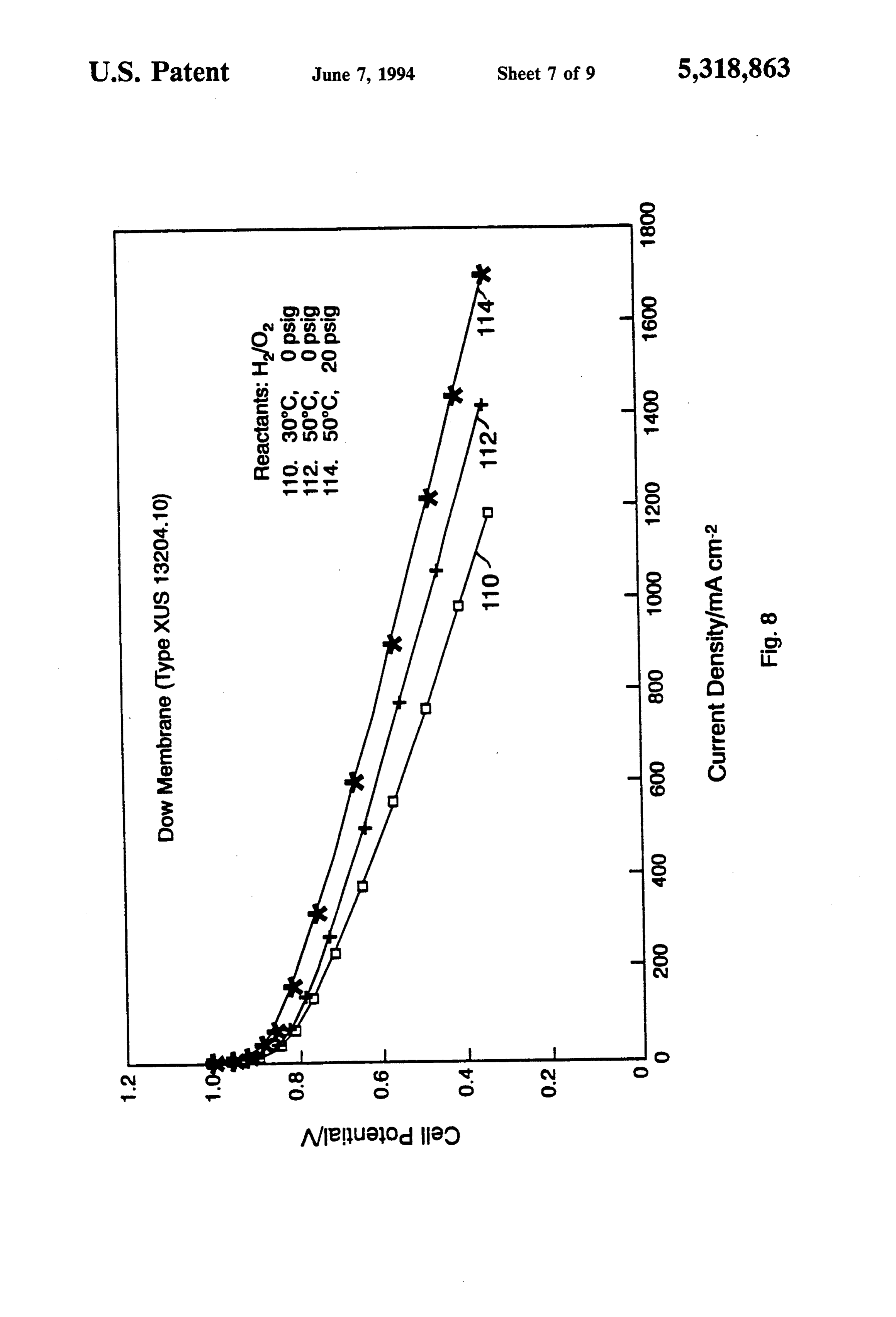
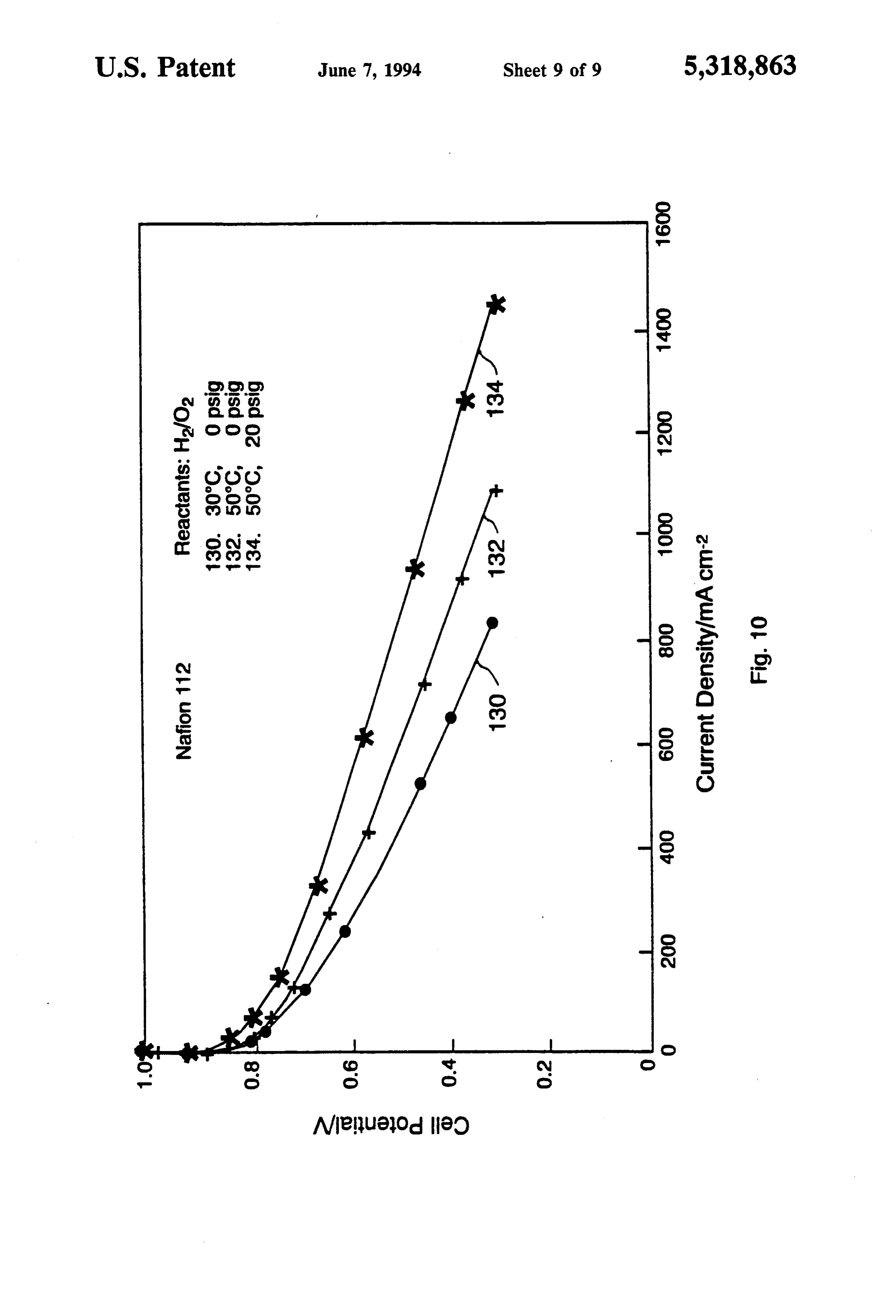
FIG. 6(b) is a side view of the fuel cell of FIG. 6(a) Furthermore, many suitable oxidizer sources (12) or after being assembled; oxidizer species are available for combining with the FIG. 7 is a graph of cell potential versus current fuel to provide a mixture suitable for powering the fuel density using a fuel cell according to FIG. 5(b) at vari cell assemblies described herein. In practice, the most ous temperatures and pressures; common oxidizer is gaseous oxygen or air. FIG. 8 is a graph of cell potential versus current The anode (18) and the cathode (20) halfcell hydro density using a fuel cell according to FIG. 6(b) at two gen and oxygen reactions preferably include catalysts to temperatures and pressures; proceed at useful rates. As such, thin catalyst layers (36) FIG. 9 is a graph of cell potential versus current and (38) are placed on the first electrode catalyst side density of a fuel cell according to FIG. 6(b) at two 10 and the second electrode catalyst side. Various materi temperatures and pressures; and als are suitable for forming such catalyst layers. These FIG. 10 is a graph of cell potential versus current materials include iridium, platinum, palladium, gold, density of a fuel cell according to FIG. 6(b) at two nickel, and various alloys of these materials. Other suit temperatures and pressures. able catalytic materials include non-metals, (for exam 5. ple, electronically conducting mixed oxides with a spi
DETAILED DESCRIPTION OF THE nel or perovskite structure). According to a more spe PREFERRED EMBODIMENTS cific embodiment, the hydrogen electrode catalyst ap Referring to FIGS. 1 and 2, there is shown in sche plied to the anode (18) is platinum, and the oxygen matic cross-section a fuel cell having features of the electrode catalyst applied to the cathode (20) is either present invention. Fuel cell assembly (5) includes gase 20 platinum or another oxygen reducing catalyst (for ex ous reactants which include a fuel source (10) and an ample, a macrocyclic chelate compound). The amount oxidizer source (12). The gases (10) and (12) diffuse of catalyst used in one embodiment is about 1 mg plati through anode backing layer (14) and cathode backing num per cm2 of electrode area. It is foreseen that in layer (16), respectively, to porous electrodes forming an creasing the platinum loading or the efficiency of plati oxidizing electrode or anode (18) and a reducing elec 25 num utilization in the electrodes will improve the fuel trode or cathode (20), which are otherwise referred to cell performance.
as the electrodes (18) and (20). The electrodes (18) and According to one embodiment of the invention, a (20) have deposits of solid electrolyte (22) and (24). perfluorinated sulfonic acid copolymer known under These electrolyte deposits (22) and (24), together with the trademark Nafion and available from E.I. DuPont an oversized membrane (30) positioned therebetween 30 de Nemours was used as the electrolyte deposits (22) with a hole (32), separate the anode (18) and the cathode and (24) on the electrode. Nonetheless, any perfluoro (20). Anode connection (42) and cathode connection carbon copolymer that could be used as an electrolyte (44) are used to interconnect with an external circuit membrane in a solid polymer fuel cell, such as those (not shown) or with other fuel cell assemblies. A mem made by Dow Chemicals Company, is equally suitable brane/electrodes assembly is prepared by putting the 35 as deposits (22) and (24) and also as the membrane (30). components shown in FIG. 2 together and pressing for In particular, in one embodiment the membrane (30) about 90 seconds at a pressure of about 1,000 psig and at was Nafion 117 having a thickness of about 175um. a temperature of about 130 C. The electrolyte deposit can be made of a material that is The above temperature and pressure conditions en characterized by a high conductivity for hydrogen ions sure that the two electrodes (18) and (20) and the elec (H) or hydronium ions (H3O). Additionally, each trolyte deposits (22) and (24) are in good contact with electrolyte deposit is permeable to the fuel, to the oxi each other and with the membrane (30) when preparing dizer, and to the products of the reaction between the the membrane/electrodes assembly. The membrane fuel and the oxidizer. Further, each electrolyte deposit (30) undergoes some deformation so that its thickness, constitutes an electron insulator, with a resistivity of at to a certain extent, and the amount of deposits (22) and 45 least about 106 ohm-centimeters. Moreover, the solid (24) are of less importance for securing a good contact electrolyte used to form the electrolyte deposits (22) between electrodes (18) and (20), electrolyte deposits and (24) is capable of being made in very thin layers, (22) and (24) and the membrane (30). The ionic compo often below one micrometer (um) in thickness. Selected nent of the fuel cell current, that is, the transfer of pro hydrated aluminum oxides (for example, pseudoboeh tons from the hydrogen electrode to the oxygen elec 50 mite), which possesses the required hydrogen ion con trode, primarily occurs through the central hole (32) ductivity, electronic resistivity, and permeability to due to the reduced internal resistance of the electrolyte fuel, oxidizer, and products of the reaction between deposits (22) and (24). A very small amount of the ionic them, are also acceptable.
current can also transfer through the portion of the The amount of electrolyte deposit that is to be made membrane (30) that is in contact with the electrolyte 55 on an electrode should be sufficient to prevent reactant deposits (22) and (24). cross-overs through the electrodes. According to one Suitable fuel sources (10) that are consumed by as embodiment, the amount of electrolyte used for the semblies made in accordance with the invention in electrolyte deposits (22) and (24) is in the range of about order to produce electrical energy are hydrogen-con 10 mg to 20 mg per about 5 cm2 electrode area. The taining materials (for example, water, methane, and exact thickness of the deposit was not determined; how methanol). According to some embodiments, the fuels ever, the deposit is thicker at the central part of the are supplied to the assemblies in liquid form, while electrode than it is around the electrode edges. Accord according to alternative embodiments, fuels are sup ing to the same embodiment, the electrolyte deposit was plied in gaseous form. According to still further em made from a 5% concentrated solution of Nafion 117. A bodiments, hydrogen is obtained from reversible metal 65 5% concentrated solution is 5 grams of solid, such as hydride formers, (for example, LaNis, FeTi and Nafion 117, per 100 ml of solvent. The solvent is prefer MnNi4.5Fe0.85, where Mm is a mischmetal, among ably a lower aliphatic alcohol, such as ethanol or iso others). propanol, or their mixtures, where 10% of the solvent
Page 15
comprises water. This solution is preferably placed in a flow of the reactants and substantially ambient tempera closed container heated in the temperature range of ture of the fuel cell.
about 200-300' C. for a period of about two to five The following examples are introduced to illustrate hours. The solution is preferably applied to the catalyst further the novelty and utility of the present invention layers (36) and (38) of the electrodes (18) and (20) by 5 but not With the intention of unduly limiting the same. successive coatings made with a small brush. After each EXAMPLE 1 coating is applied, the electrodes (18) and (20) are heated in an oven of about 80 C. for about fifteen to The graph in FIG. 3 shows the performance of a fuel twenty minutes and weighed until a required amount of 10 cell in the form of a current-potential plot for a fuel cell solid electrolyte is deposited onto the electrode surface. using electrodes obtained from E-Tek, Inc. of Framing The deposited layers of electrolyte thus attaches to the ham, Mass. The catalyst is 20% platinum-on-carbon catalyst layers (36) and (38) of the electrodes (18) and The having a loading of 1 mg platinum per cm of electrode. (20). The use of Nafion as a solid polymer electrolyte cm2 each. electrode area for the anode and the cathode is 5 membrane is more particularly described in U.S. Pat. 15 thickness 175 The membrane was made of Nafion 117 of No. 4,469,579, the disclosure of which is incorporated made of Nafionpam,117. and the solid electrolyte deposit was The amount of electrolyte in the herein by reference. dry state deposited on each electrode was 15 mg. The Embodiments of the present invention also include a fuel cell as described above was conditioned for three slightly oversized solid electrolyte membrane (30), posi days before collection of the performance data. The gas tioned between and in contact with the electrolyte de flow for the hydrogen and oxygen was maintained near posits (22) and (24), with the central part cut out. The 20 stoichiometric to the current drawn, approximately 1.1 purpose of the hole (32) in the membrane is to avoid an to the stoichiometric current. No humidification was additional electrolyte on top of the deposited layer and provided either for cell conditioning or for data collec hence to avoid an unnecessary increase in the electro lyte resistance. The purpose of the oversized membrane 25 tion. The results are presented at three temperatures, is for gasketting the perimeter of the electrodes (18) and entered 40' 30' C., C. and 50° C. Both hydrogen and oxygen separate channels through the bottom of the (20) and preventing reactant cross-overs around the cell and the unreacted electrodes. Examples of suitable membranes include the top. Approximatelyexcess exited through channels at Nafion and any other proton exchange membrane suit was maintained for both gases. of 4 inches water back pressure As expected, the cell able for solid polymer fuel cell work. Moreover, any 30 performance increased with increasing temperature. At gasketting material that can effectively attach to the 50 C. and 300 mA/cm2 of current, the cell voltage was electrode perimeter and act as a barrier between the 0.655 V, while at 30' C. and under similar conditions of hydrogen and oxygen gases would be suitable instead of current, the cell voltage was 0.615 V. a proton exchange membrane. This fuel cell was also run with air as the oxidant at It is believed that the fuel cell performance varies 35 30° C. To compensate for lower oxygen content, the air proportionately with the ratio of the area of the cutout flow volume was maintained five times that for the portion of the membrane (30) to the total electrode area. stoichiometric flow of oxygen alone. The air perfor This ratio determines the area of an electrode having mance is also shown in FIG. 3. Since a high flow of a the least resistive electrolyte pathway. For a small elec reactant tends to evaporate the generated water in the trode fuel cell having a cutout portion area of 2.25 cm2 fuel cell quickly, the use of air as an oxidant at a higher and a total electrode area of 5 cm2, this ratio is 45%. temperature is not preferred at atmospheric pressure. This would mean that the area of the electrode (18) and However, it is foreseen that the use of air is feasible, if (20) covered by the membrane (30) was 2.75 cm2, or a the cell is operating at a lower temperature and higher membrane 0.37 cm wide all around the perimeter of an pressure.
electrode. If the width of the membrane (30) is kept the 45 EXAMPLE 2 same (0.37 cm) for a bigger electrode fuel cell, the effec tive electrode area would be greater for that electrode. Referring now to FIG. 4, there is a graph which It can be calculated that for a 25 cm?electrode, the ratio shows temperature and pressure effects on fuel cell is 73%, and for a 100 cm2 electrode, 86%. Therefore, it performance of a cell assembled with electrodes having is expected that for a larger electrode area, the fuel cell 50 electrolyte deposits of 19 and 20 mg, respectively. performance will improve. If the width of the mem Other conditions for cell assembly and operation were brane (30) is changed for a larger fuel cell, this calcula similar to that described above. Curves 1 and 2 show the tion should be modified accordingly. effect of increasing pressure from 0 to 20 psig for both As is usual in fuel cell experiments involving solid hydrogen and oxygen gases and the cell temperature of polymer electrolytes, an initial period of conditioning 55 30' C. With increasing pressure of 20 psig, the cell per for a fuel cell is allowed. The initial performance for the formance at 300 mA/cm2 increases from 0.59 V to 0.64 fuel cell is low; however, the voltage and current of the V. Curves 2, 3, and 4 show temperature effect at the cell gradually increase upon running the cell for some high pressure of 20 psig. At 50° C., and 300 mA/cm2 period of time. This conditioning can be done at a tem current density, the cell voltage was 0.68 volts, an im perature of about 30' to 40 C., polarizing the cell for a provement of 25 millivolts over the 0 psig data of FIG. period of about 1 to 5 days. 3.
The practice of the invention requires no additional According to a further embodiment of the invention, humidification of the electrolyte or the reactants. 10 mg of electrolyte was deposited on each electrode. Therefore, the water generated by the fuel cell reaction The cell performance at 30 C, and 300 mA/cm2 current is not carried away from the electrolyte by a high flow 65 density was 0.59 V and at 50 C. and the same current as of reactants through the fuel cell or through operation above, the cell performance was 0.655 V. of the cell at high temperature. The preferable condi Referring now to FIG. 5(a), a schematic cross-section tions for fuel cell operation are thus near stoichiometric of an alternative embodiment according to the present
Page 16
invention is shown. A fuel cell assembly (50) is pro similar and suitable solvent. Nafion 117 has an equiva vided, where similar components as those of the fuel lent weight of approximately 1100 grams and its solu cell (5) assume identical reference numerals. In particu tion has a much higher viscosity than a solution of Na lar, the fuel cell assembly (50) also includes a fuel source fion 105. Nafion 105 has an equivalent weight of ap (10) and an oxidizer source (12) which diffuse through proximately 1,000 grams. The low viscosity solution of an anode backing layer (14) and a cathode backing layer Nafion 105 when applied to an electrode tends to pene (16), respectively, to porous electrodes forming an trate the catalyst layers (36) and (38) to the back of the anode (18) and a cathode (20). Thin catalyst layers (36) electrodes (18) and (20). When this penetration occurs, and (38) are applied on the exposed surfaces of the the diffusion characteristics of the electrodes (18) and electrodes (18) and (20), respectively, preferably in a O (20) are hampered: they becomes less diffusive. There similar manner and using similar materials as described fore, a compromise was made by mixing Nafion 117 and for the fuel cell assembly (5). The amount of catalyst is Nafion 105 solution in the 50:50 ratio. The solution is preferably approximately 0.5 mg platinum per cm2 of preferably applied to the catalyst layers (36) and of the electrode area. The electrodes (18) and (20) have depos electrodes (18) and (20) by successive coatings in a its of solid electrolytes (52) and (54), respectively, 15 similar manner as described for the fuel cell assembly where these electrolyte deposits (52) and (54), together (5), and as further described in U.S. Pat. No. 4,469,579. with an oversized non-conducting gasket (60) posi The non-conducting gasket (60) is slightly oversized tioned therebetween with a hole (62) separate the anode and positioned between and in contact with the electro (18) and the cathode (20). lyte deposits (52) and (54). The purpose of the hole (62) The electrolyte deposits (52) and (54) comprise simi 20 is to allow the flow an ionic current between the two lar materials and are applied in a similar manner as electrolyte deposits (52) and (54). The hole (62) deter described for the fuel cell assembly (5), except that no mines the active area of the fuel cell assembly (50). The electrolyte material is deposited at the respective pe size of the gasket (60), as well as the size of the central ripheries (40) of the electrodes (18) and (20). Also, the hole (62), are similar to that described for the membrane amount of the electrolyte deposits (52) and (54) is pref. 25 (30) for the fuel cell assembly (5). The gasket (60) pref. erably about the same as the electrolyte deposits (22) erably comprises polypropylene film obtained from and (24) for the fuel cell assembly (5), having a thickness Solvay Industrial Films, Incorporated, Baltimore, Md. roughly uniform near the central portions (56) of the The film is known as ALKORPROP81. Another mate electrodes (18) and (20), but which gradually decrease rial found suitable is Mylar (R). Mylar (R) is a plastic at an outer location (58) between the central portion 30 polymeric material with the chemical composition of (56) and the periphery (40) of each of the electrodes (18) polymethyl methacrylate. Other suitable materials and (20). The exposed peripheries (40) of the electrodes which could also be used are polymeric materials, such (18) and (20), which are lined with the catalyst layers as polyester, polyethylene, polyvinyl, polytetrafluoro (36) and (38), preferably combine with the gasket (60) ethylene, polyimide film, Nylon (R) tape, acetate film through hydrophobic-hydrophobic interaction when 35 tape, cellophane tape, etc.
the fuel cell (50) is assembled. However, the present It is preferred that these polymeric materials are sta invention is not limited to any particular type of interac ble at the temperature of 120 to 140° C., the range at tion with the gasket (60), as long as a bond occurs be which the solid polymer electrolyte on the electrodes tween the gasket (60) and the electrodes (18) and (20) (18) and (20) combine with each other. These materials along the peripheries (40). should preferably bond with the catalyst layers (36) and The components of the fuel cell assembly (50) are (38). The catalyst layers (36) and (38) preferably com combined together to make a single unit by inserting prise platinum-on-carbon, which is preferably mixed them between two platens of a press that is preheated to with polytetrafluoroethylene powder. Therefore, the about 135 C., keeping the components there for about catalyst layers (36) and (38) combine with the non-con three minutes, and then pressing at a pressure of about 45 ducting gasket (60) at the locations (58) and the periph 775 psig for 30 seconds. FIG. 5(b) is a side view of the eries (40), effectively forming a bond surrounding the fuel cell assembly (50) of FIG. 5(a) after being assem electrolyte deposits (52) and (54), as clearly shown in bled. This assembly procedure ensures that the two FIG. 5(b). In the solid polymer electrolyte, the poly electrodes (18) and (20) along with their electrolyte meric unit has both hydrophilic and hydrophobic chem deposits (52) and (54) are in good contact with each 50 ical units. The hydrophobic component of the solid other and with the gasket (60). The low internal ohmic polymer establishes bonding with the non-conducting resistance of the electrolyte deposits (52) and (54), and gasket (60). ALKORPROP81 is known to show slight the non-conducting nature of the gasket (60) allow the shrinkage at the temperature range of 120-140 C. ionic component of the fuel cell current to flow entirely during the exposure time of about 15 minutes. There through the central hole (62). The operation of the fuel 55 fore, the exposure time in assembling the components of cell assembly (50) is achieved near ambient conditions the fuel cell assembly (50) is set at 3 minutes. No shrink and without humidification. age problem was encountered at the temperature of The amount of electrolyte to form the electrolyte 135 C. A slight shrinkage could be conveniently uti deposits (52) and (54) should be sufficient to prevent lized for better bonding of the gasket (60) with catalyst reactant cross-overs through the electrodes (18) and layers (36) and (38) at peripheries (40), and electrolyte (20). The amount of electrolyte deposit is preferably in layers at locations (58). The shrinkage temperature of the range of about 15 mg to 20 mg per about 5 cm Mylar (R) obtained from Labelon Corporation of electrode area, although the exact thickness of the de Canadaigua, N.Y., was above 150 C. posit was not directly measured. The electrolyte depos Referring now to FIG. 6(a), a schematic cross-section its (52) and (54) are preferably made from a 50:50 mix 65 of an alternative embodiment according to the present ture of 5% concentrated solution of Nafion 117 and invention is shown. A fuel cell assembly (70) is pro Nafion 105. The solvent is preferably ethanol or isopro vided, where similar components as those of the fuel panol, or their mixtures, although it could be any other cell assembly (5) assume identical reference numerals.
Page 17
Thin catalyst layers (36) and (38) are applied in a similar bon having a loading of 0.5 mg platinum per cm of the manner as described previously for the fuel cell assen electrode. The area for the anode and the cathode is 5 bly (50). Electrolyte deposits (82) and (84), together cm2 each. The amount of electrolyte in the dry state with an oversized membrane (90) are positioned be deposited on each electrode was about 18 mg. tween and separate the anode (18) and the cathode (20). The first coating of electrolyte was made with Nafion The electrolyte deposits (82) and (84) are preferably 105 depositing about 2 mg in the electrode. The second made of the same type of materials as described for the coating was made with a 50:50 mixture of solutions electrolyte deposits (22) and (24) for the fuel cell assem Nafion 117 and Nafion 105. The third coating was with bly (5). However, the amount of deposit used is prefera Nafion 117. The subsequent coatings were made with a bly between 1 mg to 6 mg per 5 cm2 electrode area, and 10 50:50 mixture of Nafion 117 and Nafion 105, until ap is placed relatively evenly along the entire surfaces of proximately 18 mg of electrolyte was deposited. the respective electrodes (18) and (20). A polypropylene film of thickness 70 am having a The membrane (90) preferably comprises similar ma cutout area of 2.25 cm2 at the center was used to make terials described for the membrane (30) of the fuel cell the fuel cell assembly. The fuel cell was conditioned for assembly (5). However, the membrane (90) preferably 15 four days before collection of performance data. The has a low gram equivalent weight of about 1,000 grams gas flow for the hydrogen and oxygen was maintained or less and preferably has a thickness of about 125 um or near stoichiometric to the current drawn-about 1.1 to less. More particularly, the membrane (90) preferably 1.2 to the stoichiometric current. No humidification was has a gram equivalent weight of about 800-1,000 grams provided either for cell conditioning or for data collec and a thickness of about 125 um. Alternatively, the 20 tion. The results are presented at 30' and 50' C. and at membrane (90) may have a higher gram equivalent 0, 20 and 36 psig pressures for both reactants. At 30' C. weight of about 1100 grams, but should be thinner, and 300 mA/cm2 of current and 0 psig pressure as preferably having a thickness of about 50-100 um. shown by curve 100, the cell voltage is 0.71 V; the Again, a membrane having a lower equivalent weight corresponding performance at 50' C. is 0.74 V as shown has a higher density of protons in its molecular struc 25 by curve 102; and the corresponding performances at ture, and thus more easily transfers protons at a reduced 50° C., 20 and 36 psig pressures are 0.78 and 0.81 V, internal ohmic resistance. If the membrane (90) has a respectively, as shown by curves 104 and 106, respec higher equivalent weight, it should be thinner for it to tively.
operate at a reduced ohmic resistance to easily transfer The fuel cell was also run with air as the oxidant. To protons between the two electrodes. These conditions 30 compensate for the lower oxygen content, the air flow allow the fuel cell assembly (70) to operate at near ambi volume was maintained five times that for the stoichio ent conditions of temperature and pressure without metric flow of oxygen alone. The air performance is requiring humidification of the solid electrolyte. also shown by curve 108 in FIG. 7. The components are assembled in a similar manner as The stability test of this fuel cell at 20 psig pressure that described for FIGS. 5(a) and 5(b), so that the elec 35 and at the current density of 1 A/cm2 showed that no trolyte deposits (82) and (84) are in good contact with voltage loss occurred during seven days of fuel cell the membrane (90). FIG. 6(b) is a side view of the fuel operation with oxygen as the oxidant. The cell voltage cell assembly (70) of FIG. 6(a) after being assembled. remained constant at about 0.6 V. The low internal ohmic resistance of the membrane EXAMPLE 4 (90), because of its low equivalent weight and less thick ness, offers less ohmic resistance to the ionic component Referring to FIG. 8, a graph is shown illustrating of the fuel cell current, and thus ionic current transfer temperature and pressure effects on performance of a occurs through the entire membrane (90) that is in fuel cell assembled in accordance with the fuel cell contact with the electrolytes (82) and (84). assembly (70) of FIGS. 6(a) and 6(b) with electrodes The improved embodiments including the fuel cell 45 having platinum-on-carbon catalyst of about 2 mg/cm2. assemblies (50) and (70) require no additional humidifi The electrodes were first coated with about 6 mg of cation of the electrolyte or the reactants. Therefore, the Nafion 105 in the dry state. The membrane used was a water generated by the fuel cell reaction is not carried Dow membrane (type XUS 13204.10) of about 100 um away from the electrolyte by a high flow of reactants thickness, having an equivalent weight of about 800. through the fuel cell or through operation of the cell at 50 The membrane was used in the uncut form without a high temperature. The preferable conditions for fuel central hole. The fuel cell was conditioned for one day. cell operation are thus near stoichiometric flow of the Curves 110 and 112 show the effects of increasing the reactants and substantially ambient temperature of the temperature from 30" to 50 C. at 0 psig pressure. At the fuel cell. current density of 300 mA/cm2, the cell voltage in The following examples are introduced to illustrate 55 creased from 0.68 V to 0.73 V. Curves 112 and 114 further the novelty and utility of the present invention show the effects of increasing pressure from 0 to 20 psig but not with the intention of unduly limiting the same. at 50 C. At the current density of 300 mA/cm2, the cell Again, the initial conditioning of the respective fuel voltage increased from 0.73 V to 0.77 V. cells is desired for proper performance as described EXAMPLES previously, and the operation requires no additional humidification of the electrolyte or the reactants. Referring to FIG. 9, a graph is shown illustrating temperature and pressure effects on performance of a
EXAMPLE 3 fuel cell assembled according to the fuel cell assembly Referring to FIG. 7, a graph is shown illustrating the (70) with electrodes having platinum-on-carbon cata performance in the form of current-potential plot for a 65 lyst. The catalyst loading is about 1 mg platinum per fuel cell according to the fuel cell assembly (50) using cm2 of the electrode. Each electrode was first coated electrodes obtained from E-Tek, Incorporated, of Fra with about 4 mg of Nafion 105 in the dry state. Nafion mingham, Mass. The catalyst is 20% platinum-on-car 105 of thickness 125 um was used as the electrolyte
Page 18
membrane in the fuel cell. The membrane was a contin 2. The fuel cell according to claim 1, wherein said uous uncut piece that separated the electrodes of the fuel distribution member is in flow communication with fuel cell. No humidification was provided to the cell. said first electrode and wherein said oxidant distribution The fuel cell was conditioned for four days before col member is in flow communication with said second lection of data. Curves 120 and 122 show the effects of 5 electrode.
increasing temperature from 30 to 50° C. on fuel cell 3. The fuel cell according to claim 1, wherein said performance at 0 psig pressure. Curves 122 and 124 fuel distribution member supplies a gaseous fuel to said show the effects of increasing pressure from 0 to 20 psig first electrode and wherein said oxidant distribution at 50° C. At the constant current of 300 mA/cm2, 30' C. O member supplies a gaseous oxidant to said second elec and 0 psig pressure, the cell voltage was 0.55 V. At 50 trode.
C. and 0 psig pressure, the cell voltage was 0.62 V, and 4. A fuel cell for generating electricity from a reac at 50 C and 20 psig pressure, the cell voltage was 0.67 tion between a fuel source and an oxidant source, said V. fuel cell comprising:
a first porous gas diffusion electrode having a surface;
a second porous gas diffusion electrode having a
Referring to FIG. 10, a graph is shown which illus surface opposing said first electrode surface, said trates the temperature and pressure effects on perfor second electrode defining an electric field with said mance of a fuel cell assembled according to the fuel cell first electrode;
assembly (70) with electrodes having platinum-on-car a catalyst layer lining said surfaces of said first and bon catalyst. The platinum loading is about 0.5 mg per 20 second electrodes;
cm2 of the electrode. Each electrode was first coated a first electrolyte deposit placed on the center portion with about 2 mg of Nafion 105 in the dry state. Nafion of said first electrode surface leaving the outer 112 of thickness 50 um was used as the electrolyte mem periphery of said first electrode surface exposed; brane in the fuel cell. The membrane was an oversized 25 a second electrolyte deposit placed on the center piece without any central hole. No humidification was portion of said second electrode surface leaving the provided to the cell. The fuel cell was conditioned for outer periphery of said second electrode surface two days before collection of data. Curves 130 and 132 exposed; and show the effects of increasing the temperature from 30 a non-conducting film having a central hole, wherein to 50° C. on fuel cell performance at 0 psig pressure. At said non-conducting film is positioned between and the current density of 300 mA/cm2, the cell voltage in contact with said exposed surfaces of said first increased from 0.58 to 0.63 V. Curves 132 and 134 show and second electrodes, wherein said hole surrounds the effect of increasing pressure from 0 to 20 psig at 50 and contacts said first and second electrolyte de C. At the current density of 300 mA/cm2 the cell volt posits and wherein said first and second electrolyte age increased from 0.63 to 0.68 V. 35 deposits are in contact with each other. According to a further embodiment of the invention, 5. The fuel cell according to claim 4, wherein said about 16 mg of Nafion 117 in the dry state was depos non-conducting film is bonded to said first and second ited on each electrode of platinum loading 0.5 mg/cm2. electrodes and said catalyst layers. A Mylar (R) film of thickness 100 um having a central 6. The fuel cell according to claim 4, wherein said hole of 2.25 cm2 was used in assembling the fuel cell. No first and second electrolyte deposits each comprise a humidification was provided to the cell. The fuel cell perfluorocarbon copolymer proton conducting mate performance data were collected after a cell condition rial.
ing period of two days. The fuel cell performance at 30° 7. The fuel cell according to claim 6, wherein said C., 20 psig pressure and current density 300 mA/cm2 first and second electrolyte deposits in the dry state is was 0.67 V, and at 50° C. and the same pressure and 45 between about 10 to about 20 mg per 5 cm2 electrode current as above, the cell performance was 0.72 V. area of a 5% concentrated solution of a perfluorocarbon The above embodiments are given by way of example copolymer proton conducting material. and are not intended as limitations as further embodi 8. The fuel cell according to claim 4, wherein said first and second electrolyte deposits comprise a mixture ments and advances will occur to those of skill in the art which practice the present invention. 50 of at least two perfluorocarbon copolymer proton con I claim: ducting materials.
1. A fuel cell, comprising: 9. The fuel cell according to claim 4, wherein said a first electrode having a surface; non-conducting film is a polypropylene film. a second electrode having a surface opposing said 10. The fuel cell according to claim 4, wherein said first electrode surface; 55 non-conducting film is a Mylar (R) film.
an electrolyte member located between and in 11. The fuel cell according to claim 4, wherein said contact with said opposing surfaces of said first and catalyst layers are platinum.
second electrodes; 12. A fuel cell for generating electricity from a reac a non-conducting film having a central hole, said tion between a fuel source and an oxidant source, said non-conducting film positioned between said first fuel cell comprising:
and second electrodes and contacting the outer a first porous gas diffusion electrode; periphery of said opposing surfaces of said first and a second porous gas diffusion electrode, said second second electrodes, and wherein said central hole electrode defining an electric field with said first surrounds and contacts said electrolyte member; electrode;
a fuel distribution member for supplying fuel to said 65 a first electrolyte deposit placed on said first elec first electrode; and trode;
an oxidant distribution member for supplying oxidant a second electrolyte deposit placed on said second to said second electrode. electrode; and
Page 19
an electrolyte membrane positioned between and in conducting material from about 1 to about 6 mg per 5 contact with said first and second electrolyte de cm2 electrode area.
16. The fuel cell according to claim 12, wherein said posits, wherein said electrolyte membrane has an electrolyte equivalent weight and thickness to allow signifi 5 ducting material.membrane is a perfluorocarbon proton con cant transfer of protons between said first and sec 17. The fuel cell according to claim 12, wherein said ond electrodes. electrolyte membrane has an equivalent weight of about 13. The fuel cell according to claim 12, wherein said 1,000 grams or less.
first and second electrolyte deposits comprise a per 18. The fuel cell according to claim 17, wherein said fluorocarbon copolymer proton conducting material. O electrolyte membrane has a thickness of about 125 um 14. The fuel cell according to claim 12, wherein said or less.
19. The fuel cell according to claim 12, wherein said first and second electrolyte deposits comprise a mixture electrolyte of at least two perfluorocarbon copolymer proton con weight. membrane is thin and has a high equivalent ducting materials. 15 20. The fuel cell according to claim 19, wherein said 15. The fuel cell according to claim 12, wherein said electrolyte membrane has an equivalent weight of about first and second electrolyte deposits in the dry state is a 1100 grams and a thickness of about 50 m or less. 5% concentrated solution of a perfluorocarbon proton
Provenance
- Collection
- Cited prior art
- Original PDF
- patentimages.storage.googleapis.com →
- Filed
- 1993-02-26
- Pages
- 19
- Method
- pdftotext (the PDF's own text layer) + pdftoppm 300dpi page scans
- Source
- Google Patents bibliographic record
- Granted
- 1994-06-07
- Inventors
- Hari P. Dhar; BCS Technology Inc
- Transcribed from
- patentimages.storage.googleapis.com →