patent · US5836290
Apparatus and method for gasifying volatile liquid fuels
17 November 1998
Page 1 — bibliographic record
United States Patent (19) 11 Patent Number: 5,836,290 Gilbert (45) Date of Patent: Nov. 17, 1998 54). APPARATUS AND METHOD FOR 2,565,767 8/1951 Gaskell, Jr.. GASIFYING VOLATILE LIQUID FUELS 3,199,847 8/1965 Wahnish .................................... 261/35 3,325,152 6/1967 Wahnish .................................... 261/46 75 Inventor: Jack J. Gilbert, Alphretta, Ga. 3.338,223 8/1967 Williams. 3,986,846 10/1976 Bivins, Jr. ............................... 261/161 4,011,847 3/1977 Fortino .................... ... 123/134 73 ASSignee: The Georporation, Shelby 4,149,853 4/1979 DesMarais, Jr. et al. .................. 44/50 ownsnup, Micn. 4,270,505 6/1981 Johnson .................. ... 123/522 4,271,098 6/1981 Henning et al. ... 261/66 21 Appl. No.: 594,684 4,399,079 8/1983 Lowe .......... ... 261/55 4,551,153 11/1985 Won ......... ... 261/91 22 Filed: Jan. 29, 1996 5,004,571 4/1991 Litz et al. ... 261/91 O O 5,108,662 4/1992 Litz et al. ... 261/16 Related U.S. Application Data 5,168,836 12/1992 Kraus .................................... 123/25 F 63 Continuation of Ser. No. 506,322, Jul. 24, 1995, abandoned. Primary Examiner David A. Okonsky (51) Int. Cl. ............................................... F02M 17/02 Attorney, Agent, or Firm Brooks & Kushman P.C. 52 U.S. Cl. ............................................. 123/522; 123/1 A 58 Field of Search ..................................... 123/522, 1A, 57 ABSTRACT 123/3; 261/DIG. 83 A fuel System (10,10") including apparatus (12) for gasifying
Volatile liquid fuels by introducing dried air and a volatile 56) References Cited liquid fuel into a round mixing chamber (46) for circular
lower extremity (48) of the mixing chamber is removed 349.211 9/1886 Cottrell. through a liquid outlet (56). A gas mixture of air and fuel at 527,639 10/1894 Westcott. an upper extremity (50) of the mixing chamber is delivered 1,180,389 4/1916 Friend. through a gas outlet (60) for combustion by an internal 1,598.243 8/1926 Chapin. combustion engine.
2,351,072 6/1944 Schmidt. 26 Claims, 4 Drawing Sheets
w -- -- 40
x O 100 12 - 114 6. a; 102 s / -/ a 10 ---
Page 2
Drawing sheet — no readable text.
Page 3
Drawing sheet — no readable text.
Page 4
Drawing sheet — no readable text.
Page 5
Drawing sheet — no readable text.
Page 6
APPARATUS AND METHOD FOR having a lower end that is communicated with the upper GASIFYING VOLATILE LIQUID FUELS extremity of the mixing chamber and having an upper end that is communicated with the collection chamber. The
This is a continuation of application Ser. No. 08/506,322 Vertically extending gas outlet member has a horizontal filed on Jul. 24, 1995 now abandoned. croSS Section of a Smaller Size than both the mixing chamber and the collection chamber. Also, the housing includes an
TECHNICAL FIELD upper wall defining the upper extremity of the mixing This invention relates to apparatus and a method for chamber, and the lower end of the Vertically extending gas gasifying volatile liquid fuels for combustion and also the housing intoprojects outlet member downwardly below the upper wall of relates to a fuel System that includes the gasifying apparatus Furthermore, the gas outletextremity the upper includes of the mixing chamber.
a gas delivery member for performing the method. Supported by the housing centrally within the collection BACKGROUND ART chamber and the gas outlet member.
The apparatus also includes a holder for a desiccant
U.S. Pat. No. 4,426,984 Gilbert discloses apparatus for 15 through which air is passed to provide the dried air fed to the gasifying a volatile liquid fuel Such as gasoline, methanol housing inlet, as well as including a holder for a catalyst and the like for combustion by an internal combustion through which the Volatile liquid fuel is passed prior to being engine. fed to the housing inlet.
Other fuel carburetors and delivery systems for fuel are Another object of the present invention is to provide an disclosed by United States Patents: U.S. Pat. Nos. 349,211 improved method for gasifying Volatile liquid fuels for Cottrell; 527,639 Westcott; 1,180,389 Friend; 1,598,243 combustion.
Chapin; 1,883,142 Wannack, 1,889,162 Thomas et al; 2.351, In carrying out the above object, the method for gasifying 072 Schmidt; 2,565,767 Gaskell, Jr.; 3,338,223 Williams; Volatile fuels is performed by introducing dried air into a 3,986.846 Bivins, Jr., 4,149,853 Des Marais, Jr. et al; 4,270, generally round mixing chamber having lower and upper 505 Johnson; and 4,271,098 Henning et al. 25 extremities and by also introducing a volatile liquid fuel into
DISCLOSURE OF INVENTION the mixing chamber for circular flow and mixing with the air. Liquid fuel is removed from the lower extremity of the
One object of the present invention is to provide improved mixing chamber, and a gas mixture of air and fuel is apparatus for gasifying volatile liquid fuels for combustion. removed from the upper extremity of the mixing chamber In carrying out the above object, the apparatus for gas for combustion.
ifying volatile liquid fuels for combustion includes a hous In the preferred practice of the method, the liquid fuel is ing having a generally round mixing chamber including introduced into the mixing chamber within the flow of dried lower and upper eXtremities. A housing inlet allows for the air upon introduction thereof into the mixing chamber. Also, introduction of dried air and a volatile liquid fuel into the 35 the liquid fuel is pumped from a Sump at the lower extremity mixing chamber for circular flow for mixing with each other. of the mixing chamber. Furthermore, a gas mixture of air and A liquid outlet in the housing at the lower extremity of the fuel is preferably fed to a collection chamber for delivery mixing chamber allows for removal of liquid fuel that flows therefrom for combustion.
downwardly from the mixing circular flow of the air and the Another object is to provide an improved fuel System for fuel. A gas outlet of the housing is located at the upper 40 an internal combustion engine.
extremity of the mixing chamber for delivery of a gas In carrying out the above object, the fuel System includes mixture of air and fuel that is delivered for combustion. a fuel tank for holding a volatile liquid fuel and a fuel Supply In its preferred construction, the housing includes a round pump for pumping the liquid fuel from the tank as well as floor that defines the lower extremity of the mixing chamber including fuel gasifying apparatus which includes a housing and has a central location at which the liquid outlet is located 45 having a generally round mixing chamber including lower and toward which the floor is inclined downwardly for and upper eXtremities. A holder for a desiccant through gravity flow of the liquid fuel to the outlet. This floor of the which air is passed to be dried is also provided. A housing housing preferably has a central Sump at which the liquid inlet provides for introduction of the dried air and the liquid outlet is located. Also, a pump of the apparatus is preferably fuel into the mixing chamber for circular flow for mixing provided for pumping the liquid fuel from the liquid outlet 50 with each other. A liquid outlet in the housing at the lower of the housing. extremity of the mixing chamber is also provided as is a fuel The housing of the apparatus also preferably includes an return pump for pumping liquid fuel that flows downwardly air inlet member for introducing the air into the mixing to the liquid outlet from the mixing circular flow of air and chamber and the housing inlet also includes a fuel inlet fuel back to the tank. A gas outlet of the housing is provided member located within the air inlet member to introduce the 55 at the upper extremity of the mixing chamber through which volatile liquid fuel into the mixing chamber with the air for a gas mixture of air and fuel is delivered to the engine for mixing circular flow. AS disclosed, the air inlet member is combustion.
embodied by an elbow having a first portion Supported by In the preferred construction of the fuel system, the fuel the housing and having a Second portion that extends at gasifying apparatus has the more Specific construction as about 90 to the first portion in the direction of the circular 60 discussed above.
flow within the mixing chamber. The fuel inlet member is Furthermore, two embodiments of the fuel system are located within the housing Supported first portion of the disclosed. One embodiment of the fuel system additionally elbow. includes fuel injectors for Supplying atomized liquid fuel to Preferably, the gas outlet includes a collection chamber the internal combustion engine from the fuel tank as well as that receives the gas mixture of air and fuel from the mixing 65 including a Selector for Supplying fuel from the tank to either chamber for delivery for combustion. This gas outlet mem the fuel gasifying apparatus or the fuel injectors. Another ber includes a central vertically extending gas outlet member embodiment of the fuel system includes a carburetor for
Page 7
Supplying fuel to the internal combustion engine from the 22 through a return conduit 32 as shown by arrow 34. In fuel tank as well as including a Selector for Supplying fuel addition, the regulator valve 30 under the control of the from the tank to either the fuel gasifying apparatus or the selector 18 and a valve 36 thereof Supplies fuel at about 40 carburetor. psi through a conduit 38 to the fuel injectors 16 in one mode The objects, features and advantages of the present inven of the operation, while another valve 40 of the selector then tion are readily apparent from the following detailed prevents other liquid fuel flow to the gasifying apparatus 12. In the mode of operation, the selector 18 closes the valve 36 description of the best modes for carrying out the invention when taken in connection with the accompanying drawings. while opening the valve 40 so that liquid fuel can flow from the low pressure return conduit 32 through a low preSSure
BRIEF DESCRIPTION OF DRAWINGS 1O Supply conduit 42 to the fuel gasifying apparatus 12. The fuel gasifying apparatus 12 as best illustrated in
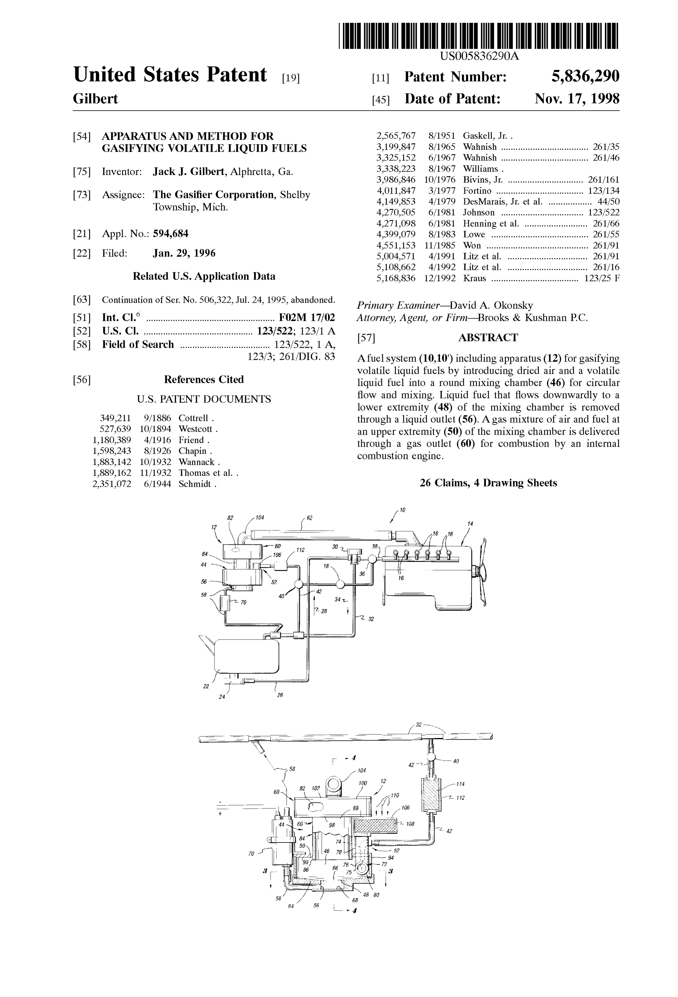
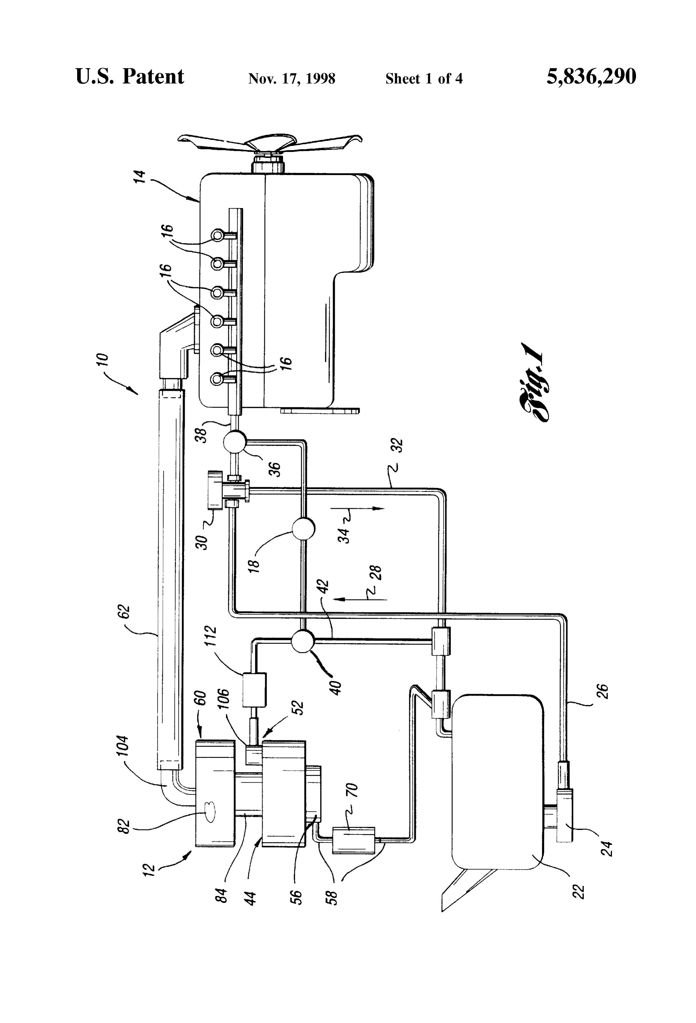
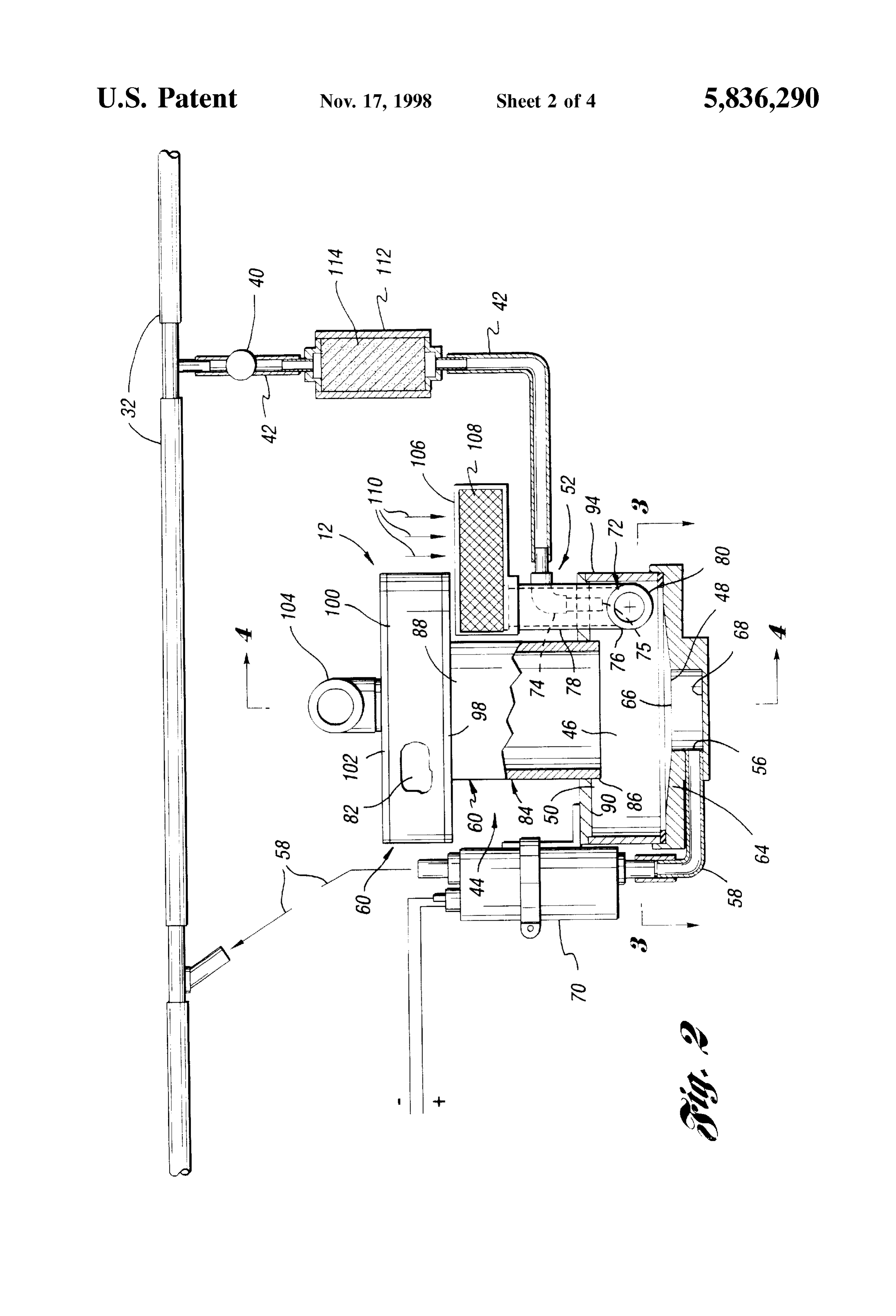
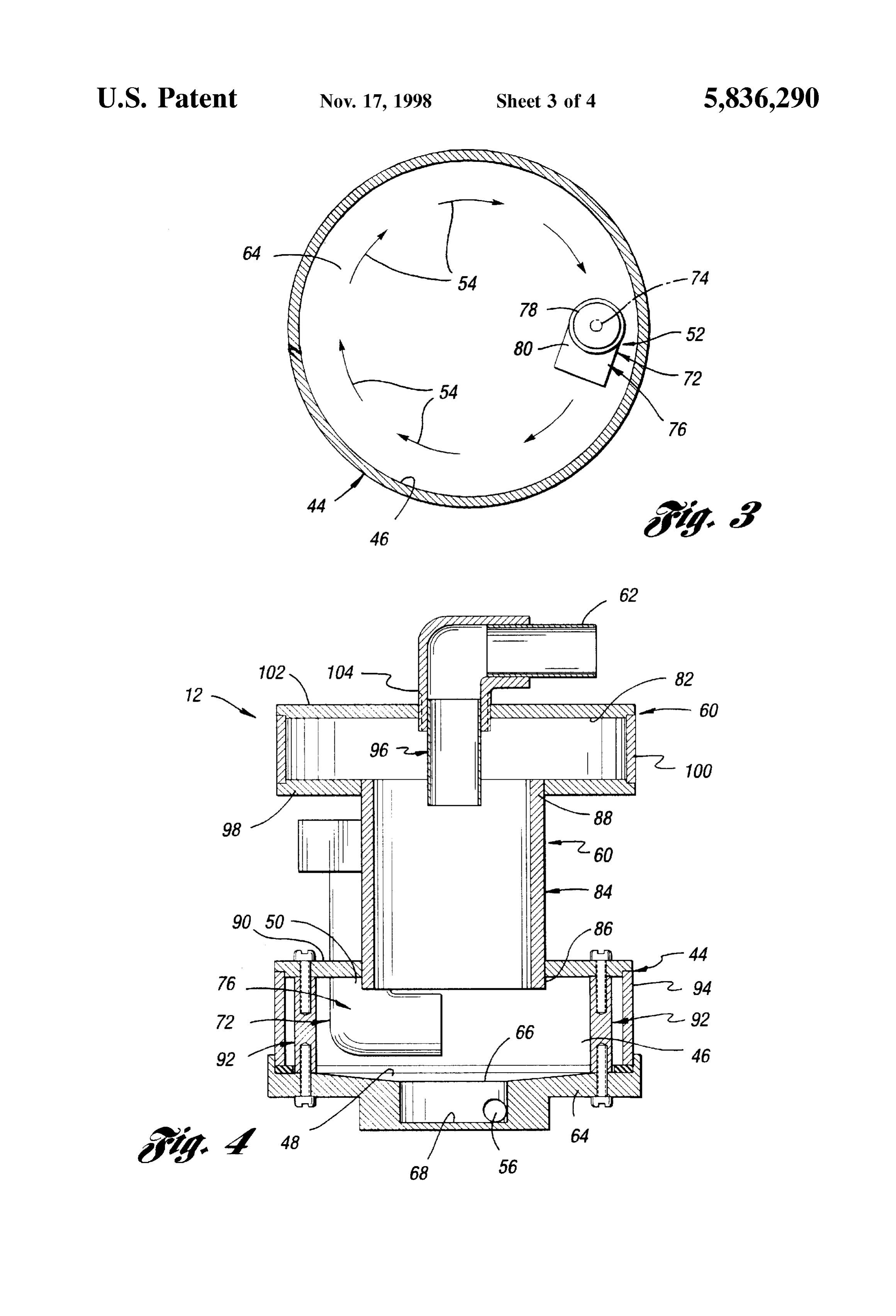
FIG. 1 is a Somewhat schematic view of an internal FIGS. 2–4 includes a housing 44 having a generally round combustion engine fuel System that is constructed in accor mixing chamber 46 (FIG. 3) including lower and upper dance with the present invention and includes fuel gasifying extremities 48 and 50, respectively. A housing inlet gener apparatus that is also constructed in accordance with the 15 ally indicated by 52 provides for introduction for dried air invention and performs a method thereof as part of the and a Volatile liquid fuel that has been passed through a operation of the fuel System which also includes fuel injec catalyst into the mixing chamber for circular flow for mixing tors as an alternate way of delivering the fuel to the engine; with each other as schematically indicated by arrows 54 in FIG. 2 is an elevational view taken partially in section of FIG. 3. As shown in both FIGS. 2 and 4, a liquid outlet 56 the fuel gasifying apparatus, of the housing is provided at the lower extremity 48 of the FIG. 3 is a sectional view taken along the direction of line mixing chamber to remove liquid fuel that flows down 3-3 in FIG. 2 to illustrate a circular mixing flow of air and wardly from the mixing circular flow of the air and the fuel. fuel within a mixing chamber of the apparatus, This liquid fuel is returned from the liquid outlet 56 through FIG. 4 is an elevational view taken in Section along the return a conduit 58 as shown in FIG. 1 to the low pressure fuel 25 conduit 32 at a location downstream from the location direction of line 4-4 in FIG. 2 to further illustrate the construction of the fuel gasifying apparatus, and where the Supply conduit 42 receives the liquid fuel for flow to the gasifying apparatus inlet 52. Housing 44 also includes
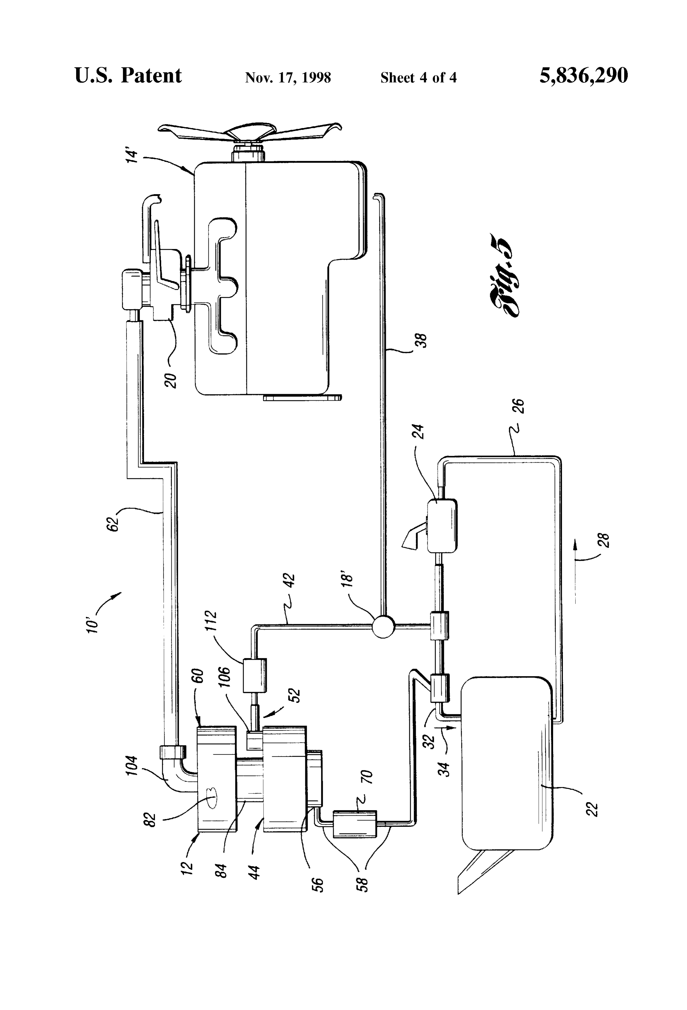
FIG. 5 is a schematic view of another engine fuel system a gas outlet 60 at the upper extremity 50 of the mixing that embodies the invention and utilizes the gasifying appa chamber 46 to provide for a flow therethrough of a gas ratus thereof but which is utilized with a vehicle carburetor mixture of air and fuel that is delivered for combustion. as opposed to fuel injectors. More Specifically, as illustrated in FIG. 1, this gas mixture BEST MODES FOR CARRYING OUT THE of air and fuel is delivered from the gas outlet 60 through a INVENTION conduit 62 to the engine 14 for combustion.
The manner in which the volatile liquid fuel is passed
As illustrated in FIG. 1, a fuel system 10 constructed in 35 through a catalyst and mixed with dried air by the circular accordance with the present invention includes liquid fuel mixing flow while continuously removing liquid fuel from gasifying apparatus 12 that is also constructed in accordance the lower extremity of the mixing chamber insures that there with the present invention and operable to perform the is a relatively high percentage of only the gas fuel mixed method thereof as is hereinafter more fully described. The with the dried air and little if any liquid fuel droplets that are fuel System 10, the fuel gasifying apparatus 12 and the 40 delivered from the gasifying apparatus to the engine for method of the invention will be described in an integrated combustion.
manner to facilitate an understanding of the different aspects In the preferred construction of the gasifying apparatus of the invention. 12, the housing 44 includes a round floor 64 that defines the The fuel system 10 is illustrated in FIG. 1 as being utilized lower extremity 48 of the mixing chamber 46 as shown in with an internal combustion engine 14 to provide a gas 45 FIG. 2. This mixing chamber floor 64 has a central location mixture of air and fuel thereto for combustion. Furthermore, 66 at which the liquid outlet 56 is located and toward which the engine 14 with which the fuel system 10 is utilized is the floor is inclined downwardly with a frustoconical shape illustrated as having fuel injectors 16 for providing an for gravity flow of the liquid fuel to the outlet. More alternate mode of fuel delivery to the engine under the specifically, the floor 64 has a central Sump 68 at which the control of a selector 18 as is hereinafter more fully 50 liquid outlet 56 is located. Furthermore, a fuel return pump described. In an alternate embodiment of the fuel system 10' 70 shown in FIGS. 1 and 2 pumps the liquid fuel from the as illustrated in FIG. 5, the engine 14 that is Supplied a gas liquid outlet 56 through the conduit 58 previously described mixture of air and fuel is illustrated as including a carburetor back to the low pressure return conduit 32 illustrated in FIG. 20 for providing an alternate mode of engine operation 1 for flow back to the fuel tank 22.
under the control of an associated Selector 18" as is also 55 As illustrated in FIGS. 2 and 3, the housing inlet 52 hereinafter more fully described. includes an air inlet member 72 for introducing the air into With continuing reference to FIG. 1, the fuel system 10 the mixing chamber 46 under the impetus of the engine will be described before a more specific discussion of the Vacuum. Furthermore, the housing inlet 52 also includes a fuel gasifying apparatus 12. This fuel System 10 includes a fuel inlet member 74 for introducing the volatile liquid fuel fuel tank 22 for holding a volatile liquid fuel that is 60 into the mixing chamber 46 with the air for the mixing combustible, Such as gasoline, benzene, ethanol (i.e. ethyl circular flow as previously described and illustrated by alcohol), methanol (i.e. methyl alcohol), naphna, and mix arrows 54 in FIG. 3. More specifically, the fuel inlet member tures thereof, etc. A fuel Supply pump 24 pumps fuel from has a lower nozzle opening 75 (FIG. 2) through which the the tank 22 through a Supply conduit 26 as shown by arrow liquid fuel is forced under pressure that generates a Spray of 28 at a relatively high pressure of about 50-60 psi to a 65 Small liquid droplets that form into a gas vapor upon the regulator valve 30. This regulator valve 30 reduces the circular mixing flow with the dried air. Furthermore, the air pressure of the fuel to about 6 psi for flow back to the tank inlet member 72 is illustrated as an elbow 76 having a first
Page 8
S 6 portion 78 Supported in a suitable manner by the housing 44 which the Volatile fuel is passed along the Supply conduit 42 and also having a second portion 80 that extends at about 90 prior to being fed to the housing inlet 52. More specifically, to the first portion in the direction of the circular flow within it has been found that activated charcoal works well in the mixing chamber 46 as best illustrated in FIG. 3. catalyzing the fuel So as to prevent build-up of accumula Furthermore, the fuel inlet member 74 is located within the tions from the fuel in the gasifying apparatus between the housing supported first portion 78 of the elbow 76. inlet 52 and the outlets 56 and 60. Furthermore, the process As illustrated in FIGS. 1, 2 and 4, the gas outlet 60 of the for creating the activated charcoal is illustrated in the gasifying apparatus 12 includes a collection chamber 82 that following example:
receives the gas mixture of air and fuel from the upper (a) Provide a quantity of approximately 20–40 grams of extremity of the mixing chamber for delivery under the impetus of the engine vacuum for combustion by the engine animal bone charcoal of six to eight mesh. as previously described. Furthermore, the gas outlet 60 (b) Provide cupric chloride CuCl2(H0) crystals pre includes a central vertically extending gas outlet member 84 pared in a solution of methanol with a ratio of 100 ml. having a lower end 86 that is communicated as best shown methanol to about 50-170 grams of cupric chloride. in FIGS. 2 and 4 with the upper extremity 50 of the mixing 15 (c) Place the charcoal granules into an open vessel and chamber 46. An upper end 88 of the gas outlet member 84 pour the dissolved cupric chloride-methanol Solution is communicated with the collection chamber 82 as shown onto the charcoal. Permit Saturation to take place for in FIG. 4. This vertically extending gas outlet member 84 approximately 10 to 15 minutes. has a horizontal croSS Section of a Smaller size than both the (d) Remove the charcoal material from the solution and mixing chamber 46 and the collection chamber 82. dry the charcoal in hot air to evaporate the methanol As best illustrated in FIG. 4, the housing 44 of the fuel using a heat gun or other equivalent heating means So gasifying apparatus 12 is illustrated as including an upper as to allow cupric chloride Salt crystals to remain in the wall 90 that defines the upper extremity 50 of the mixing granules of animal bone charcoal. chamber 46. Connectors 92 spaced circumferentially around (e) Place the activated charcoal material in a sealed the mixing chamber secure the upper wall 90 to the floor 64 25 container to prevent any moisture accumulation until as shown in FIG. 4 with an outer annular wall 94 therebe ready for use.
tween So as to thereby provide the mixing chamber with its It has been found that metallic Salts work best in creating round shape. Furthermore, the lower end 86 of the vertically the activated charcoal. For instance, Silver chloride and extending gas outlet member 84 projects downwardly below nickel chloride may also be used in step (b) of the example, the upper wall 90 of the housing 44 into the upper extremity but cupric chloride is preferred due to its low cost and 50 of the mixing chamber 46. This construction prevents effectiveness. Furthermore, it has been found that lower liquid fuel from migrating upwardly from the mixing cham alkyl alcohols are most effective in dissolving the metallic ber 46 along with the gas mixture of air and fuel to the Salt and provide for an excellent alcohol-metallic Salt Solu collection chamber 82 for the delivery for combustion. tion which readily penetrates the animal bone charcoal As best illustrated by continuing reference to FIG. 4, the 35 Substance in step (b) of the example. Examples of lower gas outlet 60 also includes a gas delivery member 96 that is alkyl alcohols which may be used as alternatives to metha Supported by the housing 44 centrally within the collection nol in Step (b) of the example are ethanol, propanol, butanol, chamber 82 and the gas outlet member 84. More specifically, pentanol, and hexanol.
the gas outlet 60 includes an annular wall 98 whose inner It is believed that the catalyst ionizes the fuel in a manner extremity is supported by the upper end 88 of the gas outlet 40 that prevents the accumulation and build-up as discussed member 84 and whose outer extremity supports the lower above. Other carbon catalysts or the like that function to end of a vertically extending annular wall 100 whose upper prevent the accumulation or build-up within the gasifying end Supports a round upper wall 102. Any Suitable type of apparatus can also be utilized.
Securement connects the walls 98, 100 and 102 to each other. With reference to FIG. 5, most of the previous description Furthermore, an elbow 104 is illustrated as being threaded 45 of FIGS. 1-4 regarding the fuel injected fuel system 10 is into the upper wall 102 with the gas delivery member also applicable to the carburetor fuel system 10' and thus will Supported by one of its ends and with its other end connected not be repeated. However, the fuel Supply pump 24 that to the conduit 62 that delivers the gas mixture of air and fuel pumps the fuel from the tank 22 through the conduit 26 only to the internal combustion engine for combustion. has a pressure of about 6 psi rather than the higher preSSure AS illustrated in FIG. 2, the gasifying apparatus 12 also 50 needed for the fuel injected embodiment. Furthermore, the includes a holder 106 for a desiccant 108 through which air selector 18 is embodied by a selector valve that alternately is passed as illustrated by arrows 110 for flow to the gas inlet supply the fuel to either the conduit 38 that Supplies the 52 as previously described. The desiccant may consist of carburetor 20 with fuel or to the conduit 42 that feeds the alumina or any other known equivalent. For instance, cal gasifying apparatus 12. Otherwise, the two fuel Systems are cium carbonate (CaCo.), calcium Sulfate (CaSO), Silica gel, 55 the same and the gasifying apparatus 12 of each System has or molecular sieves may also be used within filter 64 to the same construction and method of operation described remove moisture from incoming atmospheric air. The grain above.
size of alumina may be between 3-100 microns, but it has While the best modes for carrying out the invention have been found that a size range of approximately 7-15 microns been described in detail, those familiar with the art to which is the most effective in removing moisture from incoming 60 this invention relates will recognize various alternative atmospheric air. Furthermore, when operating within a designs and embodiments for practicing the invention as vehicle engine compartment, it has been found that the heat defined by the following claims.
present maintains the desiccant Sufficiently dry So that it will What is claimed is:
continue to function in effectively removing moisture from 1. Apparatus for gasifying volatile liquid fuels for the incoming air. 65 combustion, comprising:
With continuing reference to FIG. 2, the gasifying appa a housing having a generally round mixing chamber ratus 12 also includes a holder 112 for a catalyst 114 through including lower and upper eXtremities,
Page 9
a housing inlet for introducing dried air and a volatile a housing having a generally round mixing chamber liquid fuel into the mixing chamber for circular flow for including lower and upper eXtremities, mixing with each other; a housing inlet for introducing dried air and a volatile a liquid outlet in the housing at the lower extremity of the liquid fuel into the mixing chamber for circular flow for mixing chamber for removing liquid fuel that flows mixing with each other;
downwardly from the mixing circular flow of the air a liquid outlet in the housing at the lower eXtremity of the and the fuel; and mixing chamber;
a gas outlet in the housing at the upper extremity of the a pump for removing liquid fuel that flows downwardly to mixing chamber and through which a gas mixture of air the liquid outlet from the mixing circular flow of the air and fuel is delivered for combustion. 1O and the fuel; and 2. Apparatus as in claim 1 wherein the housing includes a gas outlet in the housing at the upper extremity of the a round floor that defines the lower extremity of the mixing mixing chamber through which a gas mixture of the air chamber and has a central location at which the liquid outlet and fuel is delivered for combustion, and the gas outlet is located and toward which the floor is inclined down including a collection chamber that receives the gas wardly for gravity flow of the liquid fuel to the outlet. 15 mixture of air and fuel from the mixing chamber for the 3. Apparatus as in claim 2 wherein the floor of the housing delivery for combustion.
has a central Sump at which the liquid outlet is located. 15. Apparatus for gasifying volatile liquid fuels for 4. Apparatus as in claim 1 further including a pump for combustion, comprising:
pumping the liquid fuel from the liquid outlet of the housing. a housing having a generally round mixing chamber 5. Apparatus as in claim 1 wherein the housing inlet including a lower floor and an upper wall that respec includes an air inlet member for introducing the air into the tively define lower and upper extremities of the mixing mixing chamber, and the housing inlet also including a fuel chamber;
inlet member located within the air inlet member to intro a holder for a desiccant through which air is passed to be duce the volatile liquid fuel into the mixing chamber with dried;
the air for the mixing circular flow. 25 a housing inlet for introducing the dried air and a volatile 6. Apparatus as in claim 5 wherein the air inlet member liquid fuel into the mixing chamber for circular flow for comprises an elbow having a first portion Supported by the mixing with each other;
housing and having a Second portion that extends at about a liquid outlet in the housing at the lower floor of the 90 to the first portion in the direction of the circular flow mixing chamber;
within the mixing chamber, and the fuel inlet member being a pump for removing liquid fuel that flows downwardly to located within the housing Supported first portion of the the liquid outlet from the mixing circular flow of the air elbow.
and the fuel; and 7. Apparatus as in claim 1 wherein the gas outlet includes a gas outlet in the housing at the upper extremity of the a collection chamber that receives the gas mixture of the air mixing chamber through which a gas mixture of the air and the fuel from the mixing chamber for delivery for 35 and the fuel is delivered for combustion, the gas outlet combustion.
8. Apparatus as in claim 7 wherein the gas outlet includes including a central vertically extending outlet member a central vertically extending gas outlet member having a having lower and upper ends with the lower end thereof lower end that is communicated with the upper eXtremity of projecting downwardly below the upper wall of the the mixing chamber and having an upper end that is com 40 mixing chamber, and the gas outlet including a collec municated with the collection chamber, and the vertically tion chamber that receives the gas mixture of air and extending gas outlet member having a horizontal croSS fuel from the mixing chamber through the vertically Section of a Smaller size than both the mixing chamber and extending outlet member for the delivery for combus tion.
the collection chamber.
9. Apparatus as in claim 8 wherein the housing includes 45 ing: A method for gasifying volatile liquid fuels, compris
an upper wall defining the upper eXtremity of the mixing chamber, and the lower end of the Vertically extending gas introducing dried air into a generally round mixing cham outlet member projecting downwardly below the upper wall ber having lower and upper extremities, of the housing into the upper eXtremity of the mixing introducing a volatile liquid fuel into the mixing chamber chamber. 50 for circular flow and mixing with the air; 10. Apparatus as in claim 9 wherein the gas outlet removing liquid fuel from the lower extremity of the includes a gas delivery member Supported by the housing mixing chamber; and centrally within the collection chamber and the gas outlet removing a gas mixture of air and fuel from the upper member. extremity of the mixing chamber for combustion. 11. Apparatus as in claim 1 further including a holder for 55 17. A method as in claim 16 wherein the liquid fuel is a desiccant through which air is passed to provide the dried introduced into the mixing chamber within a flow of the air fed to the housing inlet. dried air upon introduction thereof into the mixing chamber. 12. Apparatus as in claim 1 further including a holder for 18. A method as in claim 16 wherein the liquid fuel is a catalyst through which the Volatile liquid fuel is passed pumped from a Sump at the lower extremity of the mixing prior to being fed to the housing inlet. 60 chamber.
13. Apparatus as in claim 1 further including a holder for 19. A method as in claim 16 wherein the gas mixture of a desiccant through which air is passed to provide the dried air and fuel is fed to a collection chamber for delivery air fed to the housing inlet, and a holder for a catalyst therefrom for combustion.
through which the Volatile liquid fuel is passed prior to being 20. A method for gasifying volatile liquid fuels, compris fed to the housing inlet. 65 Ing:
14. Apparatus for gasifying volatile liquid fuels for introducing dried air into a generally round mixing cham combustion, comprising: ber having lower and upper extremities,
Page 10
introducing a volatile liquid fuel into the mixing chamber 24. A fuel System for an internal combustion engine, for circular flow and mixing with the air; comprising:
pumping liquid fuel from the lower extremity of the a fuel tank for holding a volatile liquid fuel; mixing chamber; a fuel Supply pump for pumping the liquid fuel from the passing a gas mixture of air and fuel from the upper 5 tank, and extremity of the mixing chamber upwardly to a collec fuel gasifying apparatus including a housing having a tion chamber; and generally round mixing chamber including a lower floor and an upper wall that respectively define lower delivering the gas mixture of air and fuel from the and upper extremities of the mixing chamber, a holder collection chamber for combustion. for a desiccant through which air is passed to be dried, 21. A fuel System for an internal combustion engine, a housing inlet for introducing the dried air and the comprising: liquid fuel into the mixing chamber for circular flow for a fuel tank for holding a volatile liquid fuel; mixing with each other, a liquid outlet in the housing at a fuel Supply pump for pumping the liquid fuel from the the lower extremity of the mixing chamber, a fuel tank, and 15 return pump for pumping liquid fuel that flows down fuel gasifying apparatus including a housing having a Wardly to the liquid outlet from the mixing circular generally round mixing chamber including lower and flow of the air and fuel back to the tank, a gas outlet in the housing at the upper eXtremity of the mixing upper extremities, a holder for a desiccant through chamber to which a gas mixture of air and fuel is which air is passed to be dried, a housing inlet for Supplied from the circular flow of air and fuel in the introducing the dried air and the liquid fuel into the mixing chamber, the gas outlet including a central mixing chamber for circular flow for mixing with each Vertically extending outlet member having lower and other, a liquid outlet in the housing at the lower upper ends with the lower end thereof projecting down extremity of the mixing chamber, a fuel return pump for wardly below the upper wall of the mixing chamber, pumping liquid fuel that flows downwardly to the and the gas outlet including a collection chamber that liquid outlet from the mixing circular flow of air and 25 receives the gas mixture of the air and fuel from the fuel back to the tank, and a gas outlet in the housing at mixing chamber through the Vertically extending outlet the upper eXtremity of the mixing chamber through member for the delivery to the engine for combustion. which a gas mixture of air and fuel is delivered to the 25. A fuel system as in claim 24 further including fuel engine for combustion. injectors for Supply atomized liquid fuel to the internal 22. A fuel System as in claim 21 further including fuel combustion engine from the fuel tank, and a Selector for injectors for Supply atomized liquid fuel to the internal Supplying fuel from the tank to either the fuel gasifying combustion engine from the fuel tank, and a Selector for apparatus or the fuel injectors.
Supplying fuel from the tank to either the fuel gasifying 26. A fuel System as in claim 24 further including a apparatus or the fuel injectors. carburetor for Supplying fuel to the internal combustion 23. A fuel System as in claim 21 further including a 35 engine from the fuel tank, and a Selector for Supplying fuel carburetor for Supplying fuel to the internal combustion from the tank to either the fuel gasifying apparatus or the engine from the fuel tank, and a Selector for Supplying fuel carburetor.
from the tank to either the fuel gasifying apparatus or the carburetor.
Provenance
- Collection
- Cited prior art
- Original PDF
- patentimages.storage.googleapis.com →
- Filed
- 1996-01-29
- Pages
- 10
- Method
- pdftotext (the PDF's own text layer) + pdftoppm 300dpi page scans
- Source
- Google Patents bibliographic record
- Granted
- 1998-11-17
- Inventors
- Jack J. Gilbert; Gasifier Corp
- Transcribed from
- patentimages.storage.googleapis.com →