patent · US4113601
Water decomposing apparatus
12 September 1978
Page 1 — bibliographic record
United States Patent (19) 11) 4,113,601 Spirig 45) Sep. 12, 1978
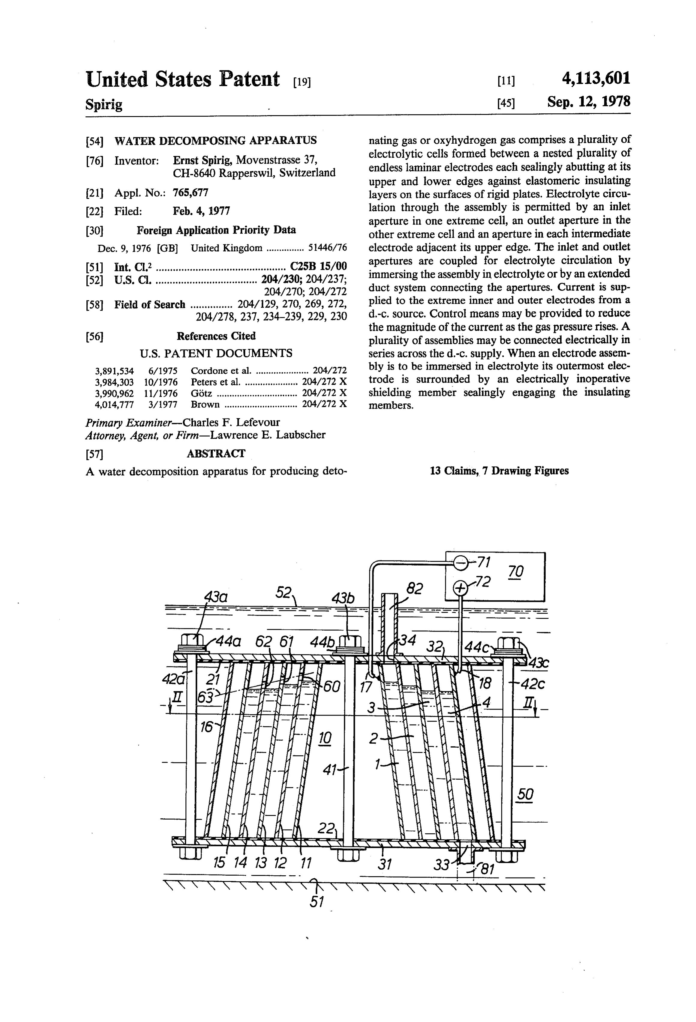
54) waTER DECOMPOSING APPARATUS nating gas or oxyhydrogen gas comprises a plurality of 76 Inventor: Ernst Spirig, Movenstrasse 37, electrolytic cells formed between a nested plurality of CH-8640 Rapperswil, Switzerland endless laminar electrodes each sealingly abutting at its upper and lower edges against elastomeric insulating 21 Appl. No.: 765,677 layers on the surfaces of rigid plates. Electrolyte circu 22 Filed: Feb. 4, 1977 lation through the assembly is permitted by an inlet (30) Foreign Application Priority Data aperture in one extreme cell, an outlet aperture in the other extreme cell and an aperture in each intermediate
Dec. 9, 1976 GB United Kingdom ............... 51446/76 electrode adjacent its upper edge. The inlet and outlet 51) int. Cl.’.................................... ::::: C25B 15/00 apertures are coupled for electrolyte circulation by 52 U.S. C. ............................... 204/230; 204/237; immersing the assembly in electrolyte or by an extended 204/270; 204/272 duct system connecting the apertures. Current is Sup 58) Field of Search ............ 204/129, 270, 269, 272, plied to the extreme inner and outer electrodes from a 204/278, 237,234-239, 229, 230 d-c. source. Control means may be provided to reduce
the magnitude of the current as the gas pressure rises. A plurality of assemblies may be connected electrically in
3,891,534 6/1975 Cordone et al. .................... 204/272 bly is to be immersed in electrolyte its outermost elec 3,984,303 10/1976 Peters et al. ..................... 204/272 X trode is surrounded by an electrically inoperative 3,990,962 11/1976 Götz ................................ 204/272 X shielding member sealingly engaging the insulating 4,014,777 3/1977 Brown ............................. 204/272 X members.
Primary Examiner-Charles F. Lefevour
Attorney, Agent, or Firm-Lawrence E. Laubscher
A water decomposition apparatus for producing deto 13 Claims, 7 Drawing Figures
SSSSAAN NASAYSS
Page 2
Drawing sheet — no readable text.
Page 3
Drawing sheet — no readable text.
Page 4
Drawing sheet — no readable text.
Page 5
DESCRIPTION OF THE PREFERRED
wATER DECOMPOSINGAPPARATUS EMBODIMENTS
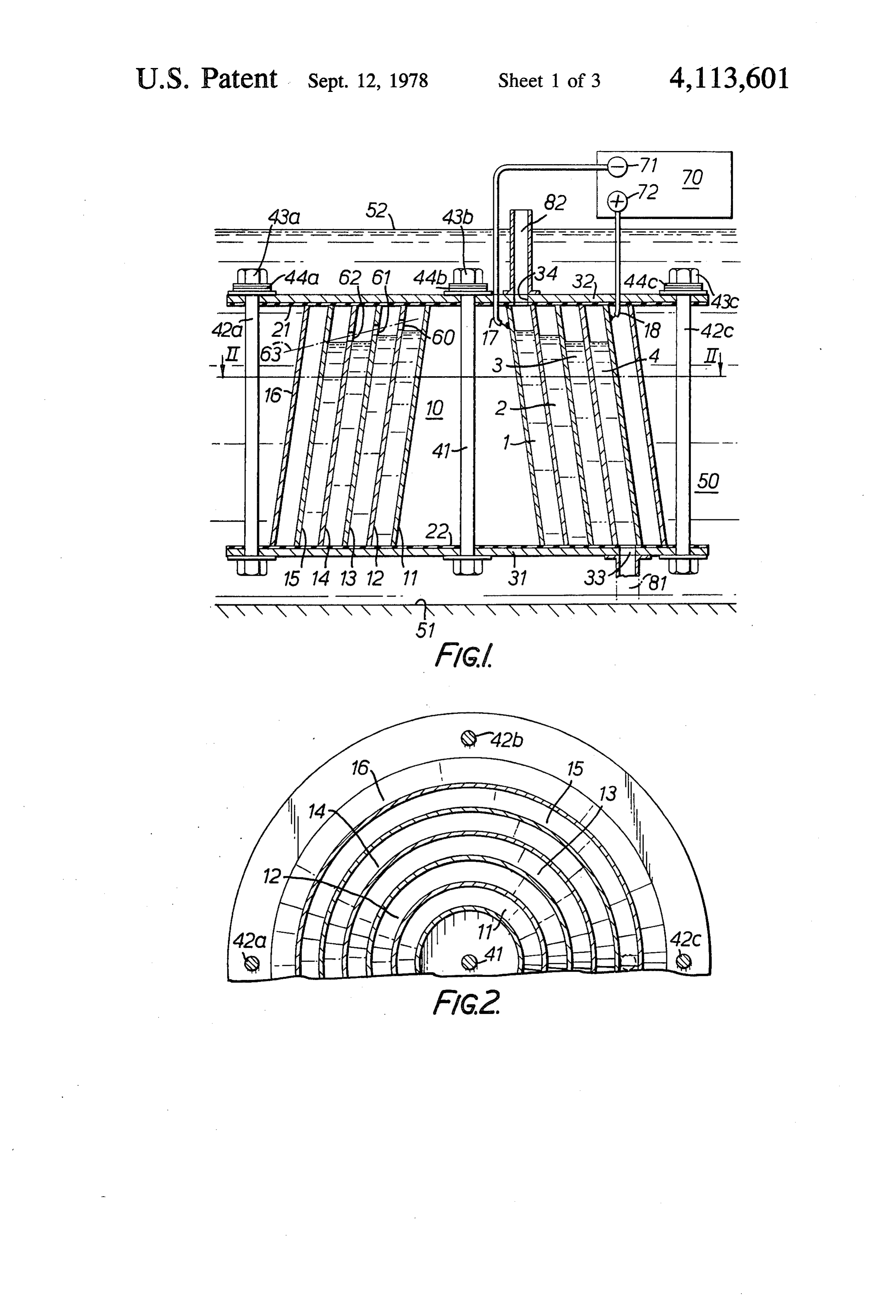
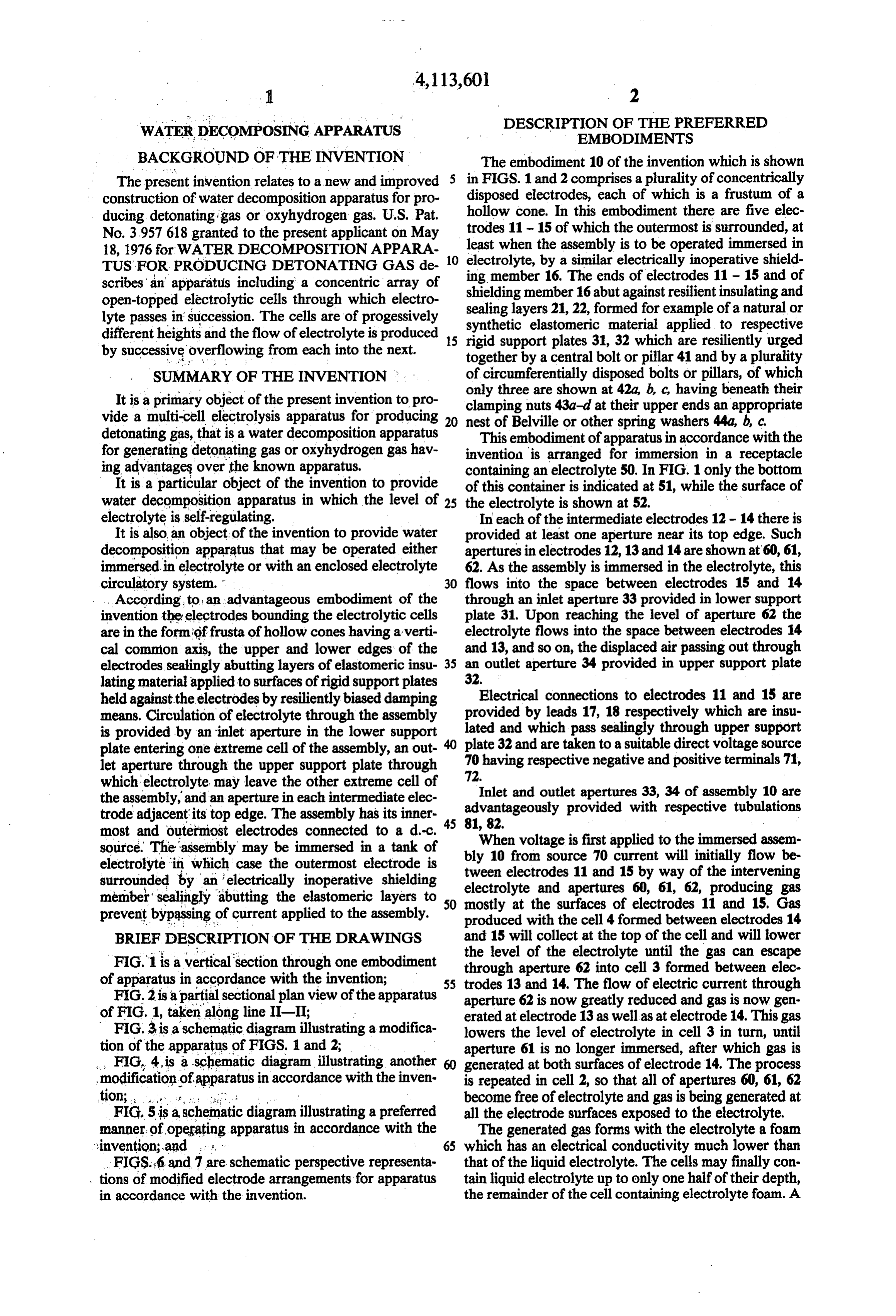
BACKGROUND OF THE INVENTION The embodiment 10 of the invention which is shown The present invention relates to a new and improved 5 in FIGS. 1 and 2 comprises a plurality of concentrically construction of water decomposition apparatus for pro disposed electrodes, each of which is a frustum of a ducing detonating gas or oxyhydrogen gas. U.S. Pat. hollow cone. In this embodiment there are five elec No. 3957618 granted to the present applicant on May trodes 11 - 15 of which the outermost is surrounded, at 18, 1976 for WATER DECOMPOSITION APPARA least when the assembly is to be operated immersed in TUS FOR PRODUCING DETONATING GAS de 10 electrolyte, by a similar electrically inoperative shield scribes an apparatus including a concentric array of ing member 16. The ends of electrodes 11 - 15 and of open-topped electrolytic cells through which electro shielding member 16 abut against resilient insulating and sealing layers 21, 22, formed for example of a natural or lyte passes in succession. The cells are of progessively synthetic elastomeric material applied to respective different heights and the flow of electrolyte is produced 15 rigid support plates 31, 32 which are resiliently urged by successive overflowing from each into the next. together by a central bolt or pillar 41 and by a plurality SUMMARY OF THE INVENTION of circumferentially disposed bolts or pillars, of which only three are shown at 42a, b, c, having beneath their
It is a primary object of the present invention to pro clamping nuts 43a-d at their upper ends an appropriate vide a multi-cell electrolysis apparatus for producing detonating gas, that is a water decomposition apparatus 20 nestThisofembodiment
Belville or other spring washers 44a, b, c.
of apparatus in accordance with the for generating detonating gas or oxyhydrogen gas hav invention is arranged for immersion in a receptacle ing advantages over the known apparatus. containing an electrolyte 50. In FIG. 1 only the bottom It is a particular object of the invention to provide of this container is indicated at 51, while the surface of water decomposition apparatus in which the level of 25 the electrolyte is shown at 52.
electrolyte is self-regulating. In each of the intermediate electrodes 12-14 there is It is also an object, of the invention to provide water provided at least one aperture near its top edge. Such decomposition apparatus that may be operated either apertures in electrodes 12, 13 and 14 are shown at 60, 61, immersed in electrolyte or with an enclosed electrolyte 62. As the assembly is immersed in the electrolyte, this circulatory system. " 30 flows into the space between electrodes 15 and 14 . . According, to an advantageous embodiment of the through an inlet aperture 33 provided in lower support invention the electrodes bounding the electrolytic cells plate 31. Upon reaching the level of aperture 62 the are in the formigffrusta of hollow cones having averti electrolyte flows into the space between electrodes 14 cal common axis, the upper and lower edges of the and 13, and so on, the displaced air passing out through electrodes sealingly abutting layers of elastomeric insu 35 an outlet aperture 34 provided in upper support plate lating material applied to surfaces of rigid support plates 32.
held against the electrodes by resiliently biased damping Electrical connections to electrodes 11 and 15 are means. Circulation of electrolyte through the assembly lated and by provided leads 17, 18 respectively which are insu which pass sealingly through upper support is provided by an inlet aperture in the lower support plate entering one extreme cell of the assembly, an out- 40 plate 32 and are taken to a suitable direct voltage source let aperture through the upper support plate through 70 having respective negative and positive terminals 71, which electrolyte may leave the other extreme cell of 72.Inlet and outlet apertures 33, 34 of assembly 10 are the assembly, and an aperture in each intermediate elec advantageously provided with respective tubulations trode adjacent its top edge. The assembly has its inner 5 81, 82.
most and outermost electrodes connected to a d-c. 4. When voltage is first applied to the immersed assem source. The assembly may be immersed in a tank of bly 10 from source 70 current will initially flow be electrolyte in which case the outermost electrode is surrounded by an electrically inoperative shielding tween electrodes 11 and 15 by way of the intervening member'sealingly abutting the elastomeric layers to 5 electrolyte and apertures 60, 61, 62, producing gas 0 mostly at the surfaces of electrodes 11 and 15. Gas prevent bypassing of current applied to the assembly. produced with the cell 4 formed between electrodes 14 BRIEF DESCRIPTION OF THE DRAWINGs and 15 will collect at the top of the cell and will lower the level of the electrolyte until the gas can escape
FIG.1 is a vertical section through one embodiment through aperture 62 into cell 3 formed between elec of apparatus in accordance with the invention;
FIG. 2 is apartial sectional plan view of the apparatus 55 trodes 13 and 14. The flow of electric current through aperture 62 is now greatly reduced and gas is now gen of FIG. 1, taken along line II-II;
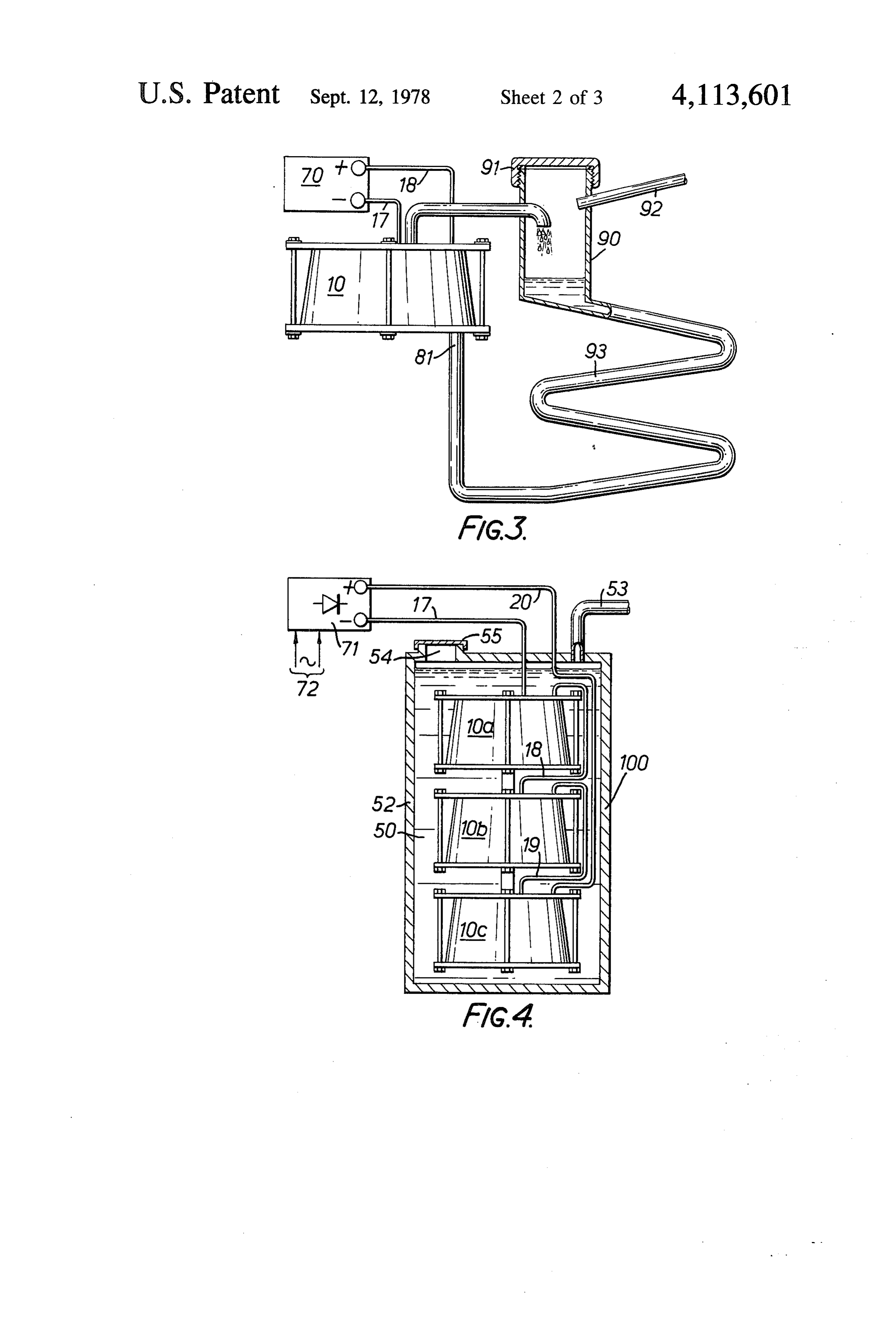
FIG. 3 is a schematic diagram illustrating a modifica erated at electrode 13 as well as at electrode 14. This gas lowers the level of electrolyte in cell 3 in turn, until tion of the apparatus of FIGS. 1 and 2; aperture 61 is no longer immersed, after which gas is FIG, 4, is a schematic diagram illustrating another 60 generated at both surfaces of electrode 14. The process modification of apparatus in accordance with the inven is repeated in cell 2, so that all of apertures 60, 61, 62 tion; : . . . . . . . . . it. become free of electrolyte and gas is being generated at FIG. 5 is a schematic diagram illustrating a preferred all the electrode surfaces exposed to the electrolyte. manner of operating apparatus in accordance with the The generated gas forms with the electrolyte a foam invention; and , , 65 which has an electrical conductivity much lower than FIGS. 6 and 7 are schematic perspective representa that of the liquid electrolyte. The cells may finally con , tions of modified electrode arrangements for apparatus tain liquid electrolyte up to only one half of their depth, in accordance with the invention. the remainder of the cell containing electrolyte foam. A
Page 6
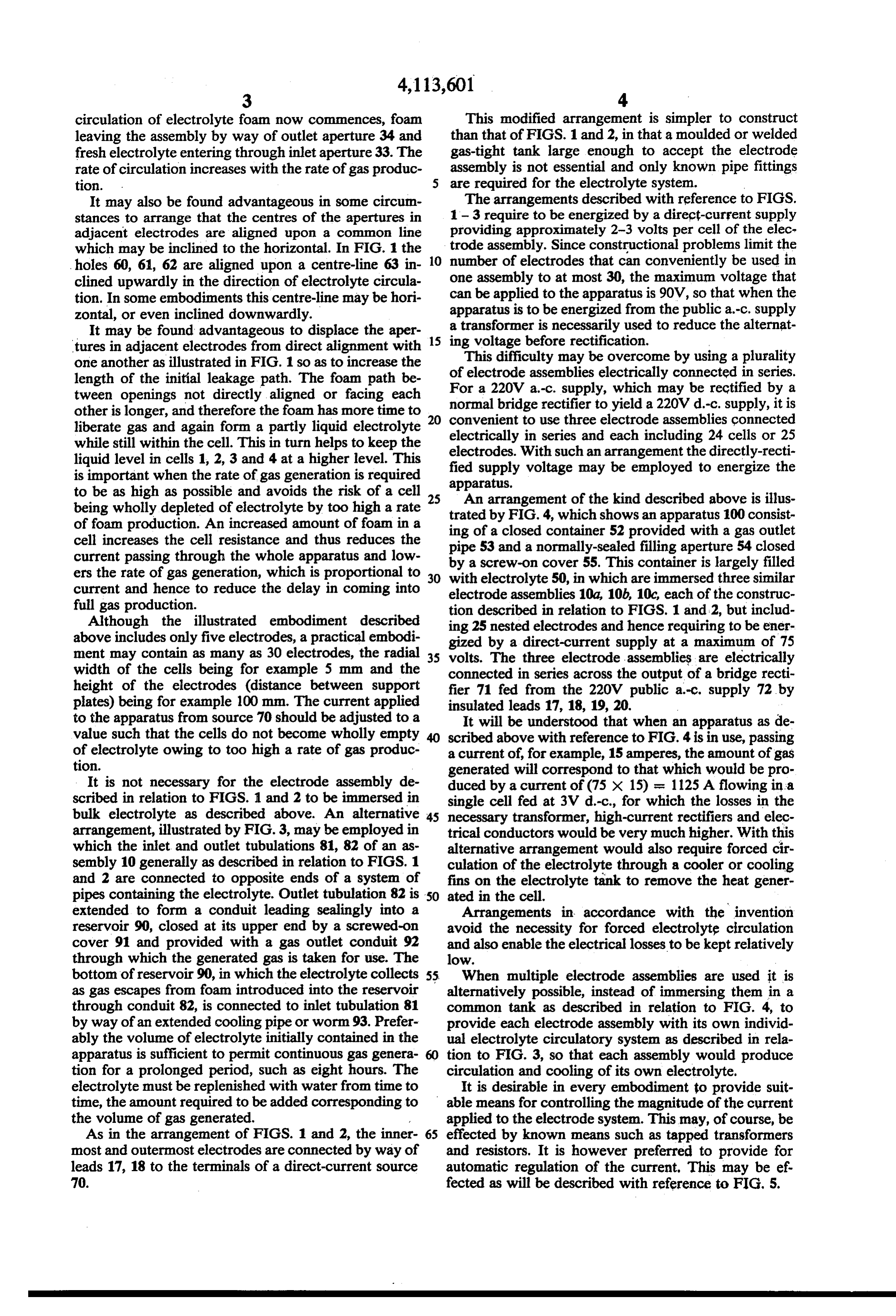
circulation of electrolyte foam now commences, foam This modified arrangement is simpler to construct leaving the assembly by way of outlet aperture 34 and than that of FIGS. 1 and 2, in that a moulded or welded fresh electrolyte entering through inlet aperture 33. The gas-tight tank large enough to accept the electrode rate of circulation increases with the rate of gas produc assembly is not essential and only known pipe fittings tion. are required for the electrolyte system. It may also be found advantageous in some circum The arrangements described with reference to FIGS. stances to arrange that the centres of the apertures in 1-3 require to be energized by a direct-current supply adjacent electrodes are aligned upon a common line providing approximately 2-3 volts per cell of the elec which may be inclined to the horizontal. In FIG. 1 the O trode assembly. Since constructional problems limit the holes 60, 61, 62 are aligned upon a centre-line 63 in number of electrodes that can conveniently be used in clined upwardly in the direction of electrolyte circula one assembly to at most 30, the maximum voltage that tion. In some embodiments this centre-line may be hori can be applied to the apparatus is 90V, so that when the apparatus is to be energized from the public a.-c. supply zontal, or even inclined downwardly.
It may be found advantageous to displace the aper a transformer is necessarily used to reduce the alternat tures in adjacent electrodes from direct alignment with 15 ingThis voltage before rectification.
difficulty may be overcome by using a plurality one another as illustrated in FIG. 1 so as to increase the length of the initial leakage path. The foam path be of electrode assemblies electrically connected in series. tween openings not directly aligned or facing each For a 220V a.-c. supply, which may be rectified by a normal bridge rectifier to yield a 220V d.-c. supply, it is other is longer, and therefore the foam has more time to 20 convenient liberate gas and again form a partly liquid electrolyte electrically to use three electrode assemblies connected in series and each including 24 cells or 25 while still within the cell. This in turn helps to keep the electrodes. With such an arrangement the directly-recti liquid level in cells 1, 2, 3 and 4 at a higher level. This is important when the rate of gas generation is required fied supply voltage may be employed to energize the to be as high as possible and avoids the risk of a cell 25 apparatus.
An arrangement of the kind described above is illus being wholly depleted of electrolyte by too high a rate trated of foam production. An increased amount of foam in a ing of by FIG. 4, which shows an apparatus 100 consist a closed container 52 provided with a gas outlet cell increases the cell resistance and thus reduces the pipe 53 and a normally-sealed filling aperture 54 closed current passing through the whole apparatus and low by ers the rate of gas generation, which is proportional to 30 witha screw-on electrolyte cover 55. This container is largely filled 50, in which are immersed three similar current and hence to reduce the delay in coming into electrode assemblies 10a, 10b, 10c, each of the construc full gas production. tion described in relation to FIGS. 1 and 2, but includ Although the illustrated embodiment described ing 25 nested electrodes and hence requiring to be ener above includes only five electrodes, a practical embodi gized by a direct-current supply at a maximum of 75 ment may contain as many as 30 electrodes, the radial 35 volts. The three electrode assemblies are electrically width of the cells being for example 5 mm and the connected in series across the output of a bridge recti height of the electrodes (distance between support fier 71 fed from the 220V public a-c, supply 72 by plates) being for example 100 mm. The current applied insulated leads 17, 18, 19, 20.
to the apparatus from source 70 should be adjusted to a It will be understood that when an apparatus as de value such that the cells do not become wholly empty scribed above with reference to FIG. 4 is in use, passing of electrolyte owing to too high a rate of gas produc a current of, for example, 15 amperes, the amount of gas tion. generated will correspond to that which would be pro It is not necessary for the electrode assembly de duced by a current of (75 x 15) = 1125A flowing in a scribed in relation to FIGS. 1 and 2 to be immersed in single cell fed at 3V d.-c., for which the losses in the bulk electrolyte as described above. An alternative 45 necessary transformer, high-current rectifiers and elec arrangement, illustrated by FIG. 3, may be employed in trical conductors would be very much higher. With this which the inlet and outlet tubulations 81, 82 of an as alternative arrangement would also require forced cir sembly 10 generally as described in relation to FIGS. 1 culation of the electrolyte through a cooler or cooling and 2 are connected to opposite ends of a system of fins on the electrolyte tank to remove the heat gener pipes containing the electrolyte. Outlet tubulation 82 is 50 ated in the cell.
extended to form a conduit leading sealingly into a Arrangements in accordance with the invention reservoir 90, closed at its upper end by a screwed-on avoid the necessity for forced electrolyte circulation cover 91 and provided with a gas outlet conduit 92 and also enable the electrical losses to be kept relatively through which the generated gas is taken for use. The low.
bottom of reservoir 90, in which the electrolyte collects 55. When multiple electrode assemblies are used it is as gas escapes from foam introduced into the reservoir alternatively possible, instead of immersing them in a through conduit 82, is connected to inlet tubulation 81 common tank as described in relation to FIG. 4, to by way of an extended cooling pipe or worm 93. Prefer provide each electrode assembly with its own individ ably the volume of electrolyte initially contained in the ual electrolyte circulatory system as described in rela apparatus is sufficient to permit continuous gas genera tion to FIG. 3, so that each assembly would produce tion for a prolonged period, such as eight hours. The circulation and cooling of its own electrolyte. electrolyte must be replenished with water from time to It is desirable in every embodiment to provide suit time, the amount required to be added corresponding to able means for controlling the magnitude of the current the volume of gas generated. applied to the electrode system. This may, of course, be As in the arrangement of FIGS. 1 and 2, the inner 65 effected by known means such as tapped transformers most and outermost electrodes are connected by way of and resistors. It is however preferred to provide for leads 17, 18 to the terminals of a direct-current source automatic regulation of the current, This may be ef. 70. fected as will be described with reference to FIG. 5.
Page 7
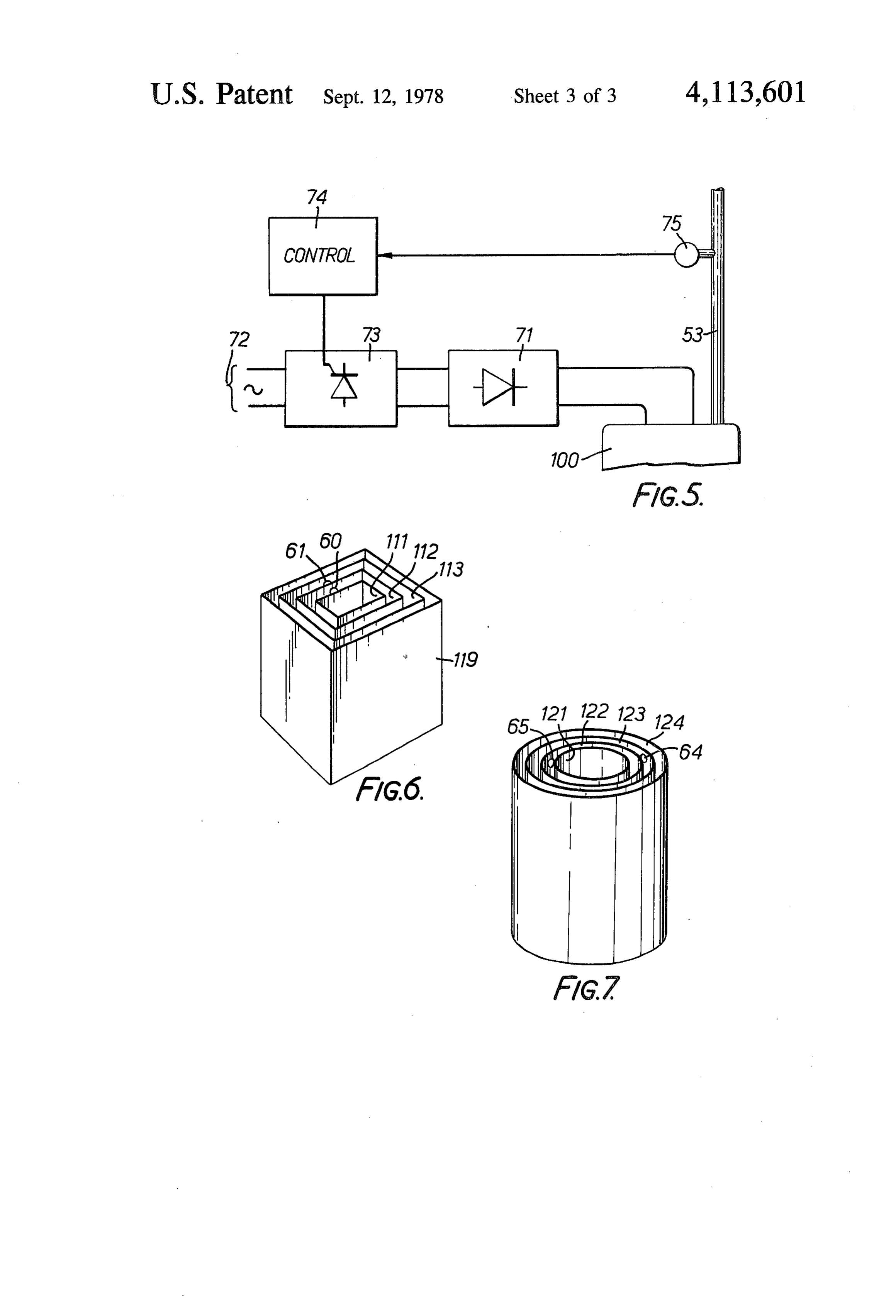
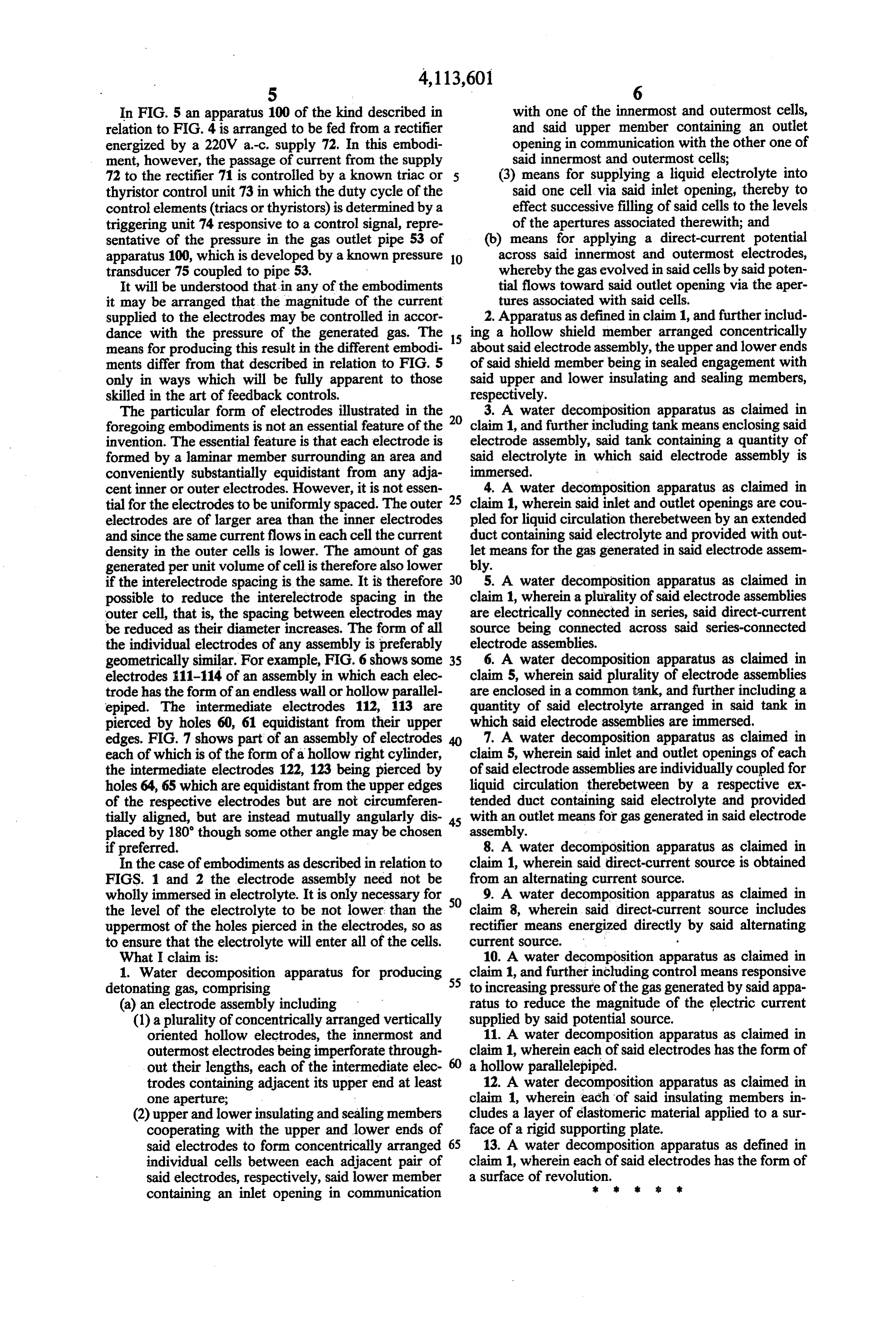
In FIG. 5 an apparatus 100 of the kind described in with one of the innermost and outermost cells, relation to FIG. 4 is arranged to be fed from a rectifier and said upper member containing an outlet energized by a 220V a-c, supply 72. In this embodi opening in communication with the other one of ment, however, the passage of current from the supply said innermost and outermost cells; 72 to the rectifier 71 is controlled by a known triac or 5 (3) means for supplying a liquid electrolyte into thyristor control unit 73 in which the duty cycle of the said one cell via said inlet opening, thereby to control elements (triacs or thyristors) is determined by a effect successive filling of said cells to the levels triggering unit 74 responsive to a control signal, repre of the apertures associated therewith; and sentative of the pressure in the gas outlet pipe 53 of (b) means for applying a direct-current potential apparatus 100, which is developed by a known pressure 10 across said innermost and outermost electrodes, transducer 75 coupled to pipe 53. whereby the gas evolved in said cells by said poten It will be understood that in any of the embodiments tial flows toward said outlet opening via the aper it may be arranged that the magnitude of the current tures associated with said cells. supplied to the electrodes may be controlled in accor 2. Apparatus as defined in claim 1, and further includ dance with the pressure of the generated gas. The 15 ing a hollow shield member arranged concentrically means for producing this result in the different embodi about said electrode assembly, the upper and lower ends ments differ from that described in relation to FIG. 5 of said shield member being in sealed engagement with only in ways which will be fully apparent to those said upper and lower insulating and sealing members, skilled in the art of feedback controls. respectively.
The particular form of electrodes illustrated in the 20 3. A water decomposition apparatus as claimed in foregoing embodiments is not an essential feature of the claim 1, and further including tank means enclosing said invention. The essential feature is that each electrode is electrode assembly, said tank containing a quantity of formed by a laminar member surrounding an area and said electrolyte in which said electrode assembly is conveniently substantially equidistant from any adja immersed.
cent inner or outer electrodes. However, it is not essen 4. A water decomposition apparatus as claimed in tial for the electrodes to be uniformly spaced. The outer 25 claim 1, wherein said inlet and outlet openings are cou electrodes are of larger area than the inner electrodes pled for liquid circulation therebetween by an extended and since the same current flows in each cell the current duct containing said electrolyte and provided with out density in the outer cells is lower. The amount of gas let means for the gas generated in said electrode assem generated per unit volume of cell is therefore also lower bly.
if the interelectrode spacing is the same. It is therefore 30 5. A water decomposition apparatus as claimed in possible to reduce the interelectrode spacing in the claim 1, wherein a plurality of said electrode assemblies outer cell, that is, the spacing between electrodes may are electrically connected in series, said direct-current be reduced as their diameter increases. The form of all source being connected across said series-connected the individual electrodes of any assembly is preferably electrode assemblies.
geometrically similar. For example, FIG. 6 shows some 35 6. A water decomposition apparatus as claimed in electrodes 11-114 of an assembly in which each elec claim 5, wherein said plurality of electrode assemblies trode has the form of an endless wall or hollow parallel are enclosed in a common tank, and further including a epiped. The intermediate electrodes 112, 113 are quantity of said electrolyte arranged in said tank in pierced by holes 60, 61 equidistant from their upper which said electrode assemblies are immersed. edges. FIG. 7 shows part of an assembly of electrodes 40 7. A water decomposition apparatus as claimed in each of which is of the form of a hollow right cylinder, claim 5, wherein said inlet and outlet openings of each the intermediate electrodes 122, 123 being pierced by of said electrode assemblies are individually coupled for holes 64, 65 which are equidistant from the upper edges liquid circulation therebetween by a respective ex of the respective electrodes but are not circumferen tended duct containing said electrolyte and provided tially aligned, but are instead mutually angularly dis 45 with an outlet means for gas generated in said electrode placed by 180 though some other angle may be chosen assembly.
if preferred. 8. A water decomposition apparatus as claimed in In the case of embodiments as described in relation to claim 1, wherein said direct-current source is obtained FIGS. 1 and 2 the electrode assembly need not be from an alternating current source.
wholly immersed in electrolyte. It is only necessary for 50 9. A water decomposition apparatus as claimed in the level of the electrolyte to be not lower than the claim 8, wherein said direct-current source includes uppermost of the holes pierced in the electrodes, so as rectifier means energized directly by said alternating to ensure that the electrolyte will enter all of the cells. Current SOurce.
What I claim is: 10. A water decomposition apparatus as claimed in 1. Water decomposition apparatus for producing 55 claim 1, and further including control means responsive detonating gas, comprising to increasing pressure of the gas generated by said appa (a) an electrode assembly including ratus to reduce the magnitude of the electric current (1) a plurality of concentrically arranged vertically supplied by said potential source.
oriented hollow electrodes, the innermost and 11. A water decomposition apparatus as claimed in outermost electrodes being imperforate through claim 1, wherein each of said electrodes has the form of out their lengths, each of the intermediate elec a hollow parallelepiped.
trodes containing adjacent its upper end at least 12. A water decomposition apparatus as claimed in one aperture; claim 1, wherein each of said insulating members in (2) upper and lower insulating and sealing members cludes a layer of elastomeric material applied to a sur cooperating with the upper and lower ends of face of a rigid supporting plate.
said electrodes to form concentrically arranged 65 13. A water decomposition apparatus as defined in individual cells between each adjacent pair of claim 1, wherein each of said electrodes has the form of said electrodes, respectively, said lower member a surface of revolution.
containing an inlet opening in communication k . sk
Provenance
- Collection
- Cited prior art
- Original PDF
- patentimages.storage.googleapis.com →
- Filed
- 1977-02-04
- Pages
- 7
- Method
- pdftotext (the PDF's own text layer) + pdftoppm 300dpi page scans
- Source
- Google Patents bibliographic record
- Granted
- 1978-09-12
- Inventors
- Ernst Spirig
- Transcribed from
- patentimages.storage.googleapis.com →