patent · US5053659A
Centrifugal force magnetic field variator
1 October 1991
Page 1 — bibliographic record
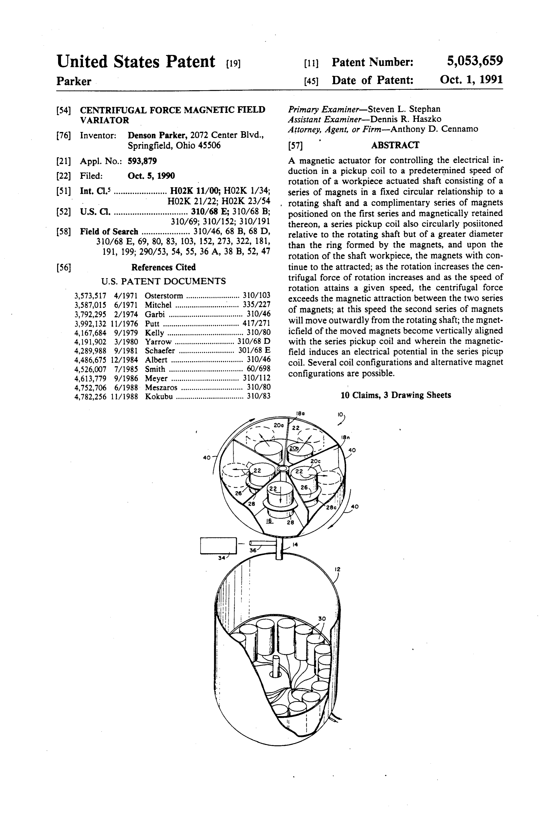
United States Patent (19) (11) Patent Number: 5,053,659 Parker (45) Date of Patent: Oct. 1, 1991 54 CENTRIFUGAL FORCE MAGNETIC FIELD Primary Examiner-Steven L. Stephan VARATOR Assistant Examiner-Dennis R. Haszko Attorney, Agent, or Firm-Anthony D. Cennamo 76 Inventor: Denson Parker, 2072 Center Blvd.,
Springfield, Ohio 4.5506 (57) ABSTRACT (21) Appl. No.: 593,879 A magnetic actuator for controlling the electrical in 22 Filed: Oct. 5, 1990 duction in a pickup coil to a predetermined speed of rotation of a workpiece actuated shaft consisting of a 51) Int. Cl........................ HO2K11/00; HO2K 1/34; series of magnets in a fixed circular relationship to a . HO2K 21/22; H02K 23/54 rotating shaft and a complimentary series of magnets (S2) U.S. C. ................................ 310/68 E; 310/68 B; positioned on the first series and magnetically retained 310/69; 310/152; 310/191 thereon, a series pickup coil also circularly positioned 58) Field of Search ..................... 310/46, 68 B, 68 D, relative to the rotating shaft but of a greater diameter 310/68 E, 69, 80, 83, 103, 152, 273, 322, 181, than the ring formed by the magnets, and upon the 191, 199; 290/53, 54, 55, 36A, 38 B, 52, 47 rotation of the shaft workpiece, the magnets with con (56 References Cited tinue to the attracted; as the rotation increases the cen
rotation attains a given speed, the centrifugal force 3,573,517 4/1971 Osterstorm ......... 310/103 exceeds the magnetic attraction between the two series 3,587,015 6/1971 Mitchel ............................... 335/227 of magnets; at this speed the second series of magnets 3,792,295 2/1974 Garbi .................................... 310/46 3,992,132 11/1976 Putt ..................................... 417/271 will move outwardly from the rotating shaft; the mgnet 4,167,684 9/1979 Kelly ..................................... 310/80 icfield of the moved magnets become vertically aligned 4,191,902 3/1980 Yarrow ....... ... 30/68 D with the series pickup coil and wherein the magnetic 4,289,988 9/1981 Schaefer . ... 301/68 E field induces an electrical potential in the series picup 4,486,675 12/1984 Albert ................................... 310/46 coil. Several coil configurations and alternative magnet 4,526,007 7/1985 Smith .................................... 60/698 configurations are possible.
4,613,779 9/1986 Meyer ................................. 310/112 4,752,706 6/1988 Meszaros .............................. 310/80 4,782,256 11/1988 Kokubu ................................. 310/83 10 Claims, 3 Drawing Sheets
Page 2
Drawing sheet — no readable text.
Page 3
Drawing sheet — no readable text.
Page 4
Drawing sheet — no readable text.
Page 5
tor; a principle of its operation is a sacrifice of power
CENTRIFUGAL VARATOR
FORCE MAGNETICFIELD but a sacrifice at the low velocity winds of inefficient electrical power generation rather than at the high effi ciency high velocity winds.
Another object of the invention is directed further to . Field of the Invention a device providing for a first and second series of per The invention relates to an improved centrifugal manent magnets rotationally positioned in a ring about force to magnetic field variator, converter brake, and the rotating shaft; the first series of magnets are magnet method for its manufacture, and more particularly the ically attracted to the fixedly positioned second series of invention is directed to a series of magnets positioned on O magnets; a series pickup coil is non-rotationally posi a rotational disc having a plurality of pickup coils posi tioned in a ring relative to the rotating shaft, but how tioned on the periphery of the disc, the opposing fields ever with an initial diameter greater than that of the pair of the magnets causing the magnets to center them of series of magnets.
selves and upon rotation of the magnets, a sufficient 15 Also an object of the invention is to provide appara rotational centrifugal force must be generated to cause tus which in operation performs wherein the speed of the magnets to overcome the attractive force of the opposing fields; hence the greater the speed of rotation, rotation of the shaft increases, the centrifugal force the further out the magnets may move from the center, exerted upon the non-fixed magnets proportionally in and electrical pickup coils positioned at an outermost 20 creases. As the centrifugal force exceeds the magnetic periphery have induced therein an electrical potential attraction force, the second series of magnets will move by the moving electrical field and again the greater the outwardly to a position directly above the ring pickup speed then the greater the relative closeness of the posi coil; at this position the magnetic field emanating from tion of the magnets and the electrical pickup windings. the ring of magnets will traverse the ring of pickup coils Wind, wave or other motion convertors or such actu and thereby induce an electrical potential therein. ated electrical generators are well known in the art and 25 Another object of the invention is to provide a novel have been used to generate electricity solely from wind and improved method of selectively providing mag or other power. Unfortunately the cost of the apparatus netic parameters and the weight of the magnets are so when equated to the electrical power generated far controlled to permit movement of the magnets at a exceeds the normal cost of any amount of electrical predetermined speed of rotation of the rotating shaft. power. The required sophistication of the apparatus is a 30 primary cost factor, more specifically the wind force is It is a principle object of the present invention to not readily calculated and there may at times be no provide apparatus and means for controlling the utiliza wind or waves, or there may be winds or waves at gale tion of a rotation shaft to a determined speed of rotation, forces. As a practical matter then, the generator must be wherein the force of the rotating shaft is utilized above capable to respond to velocities of almost no miles per 35 a predetermined speed and sacrificed below a predeter hour to velocities of fifty or more miles per hour, a neat mined speed, wherein the magnetic force of a pair of feat. The expedient mostly used is to utilize brakes of attracted permanent magnets are equated against the one form or another to dampen the speed of rotation centrifugal force of the rotating shaft, and wherein the when the wind velocity exceeds a given range; particu electrical power generated by the rotating shaft is uti larly an apparatus arranged to permit operation of a lized at higher speeds of rotation. wind generator at very low velocities is very sophisti cated and subject to damage at high wind velocities. which will becomewith
These together other objects and advantages subsequently apparent reside in the
Accordingly, the high velocity winds are being sacri details of the process and operation thereof as more ficed for the low velocity winds in complete contradis fully hereinafter are described and claimed, reference tinction to the economy of the apparatus, and, to a point 45 being had to the accompanying drawings forming a part of the system, the greater the velocity the greater the amount of electrical power generated. hereof, wherein like numerals refer to like parts 2. Description of the Prior Art throughout.
Various prior brake or impedance energy conversion applicator devices and magnetic actuators for control 50 DESCRIPTIONTHE OF THE SEVERAL VIEWS OF
DRAWINGS
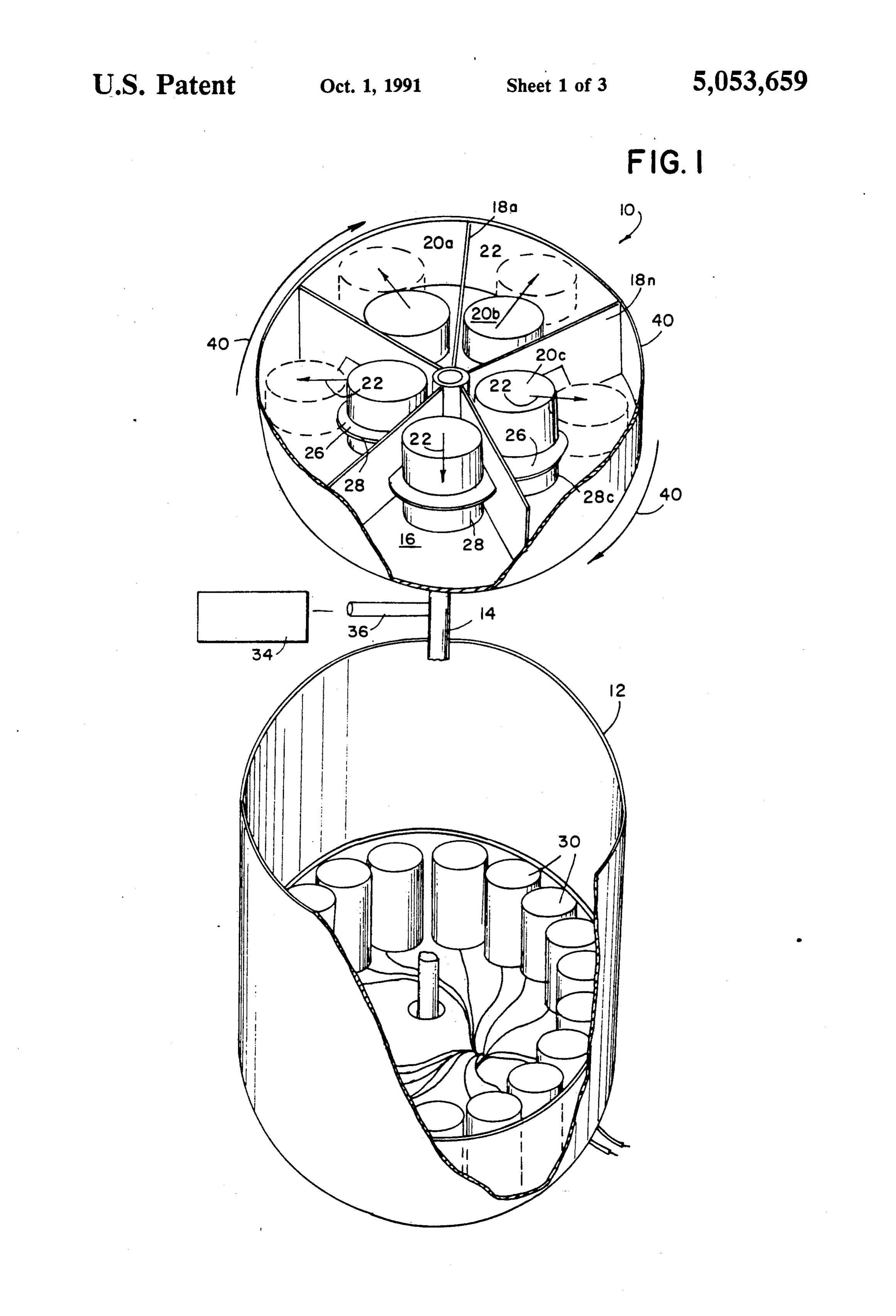
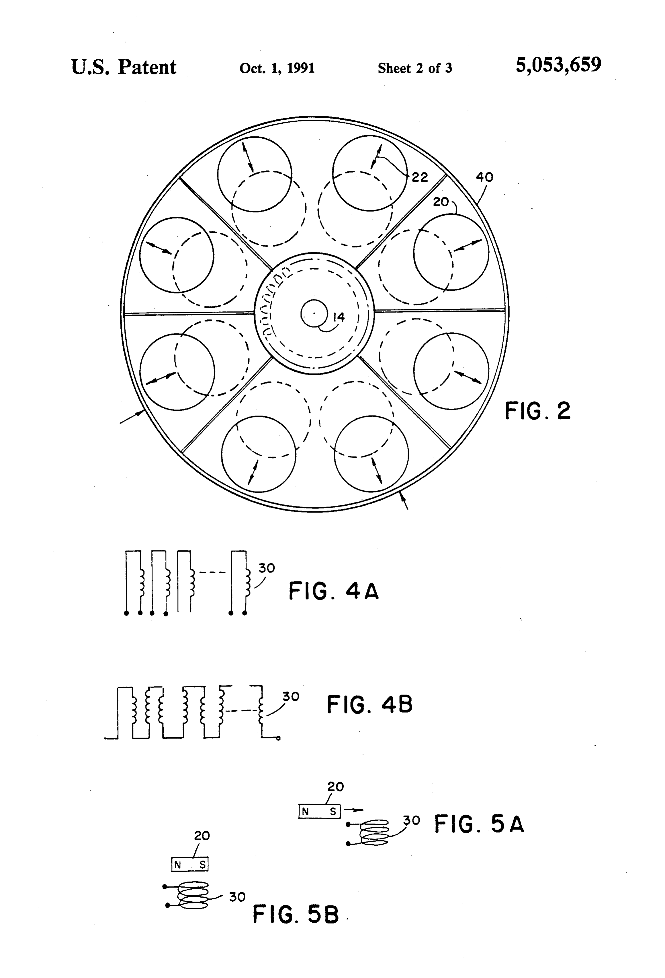
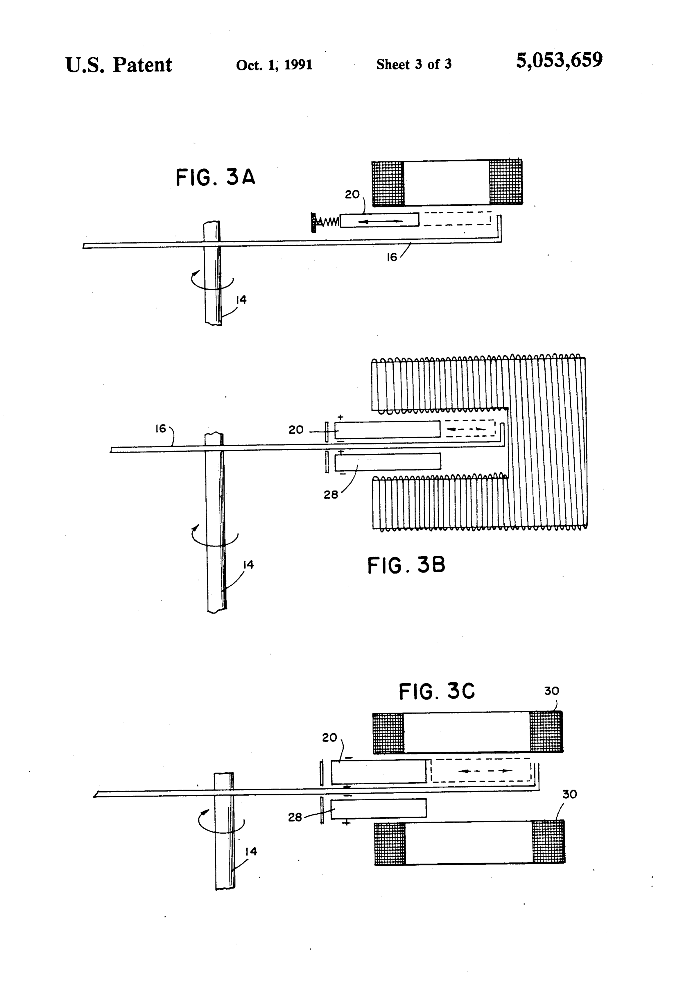
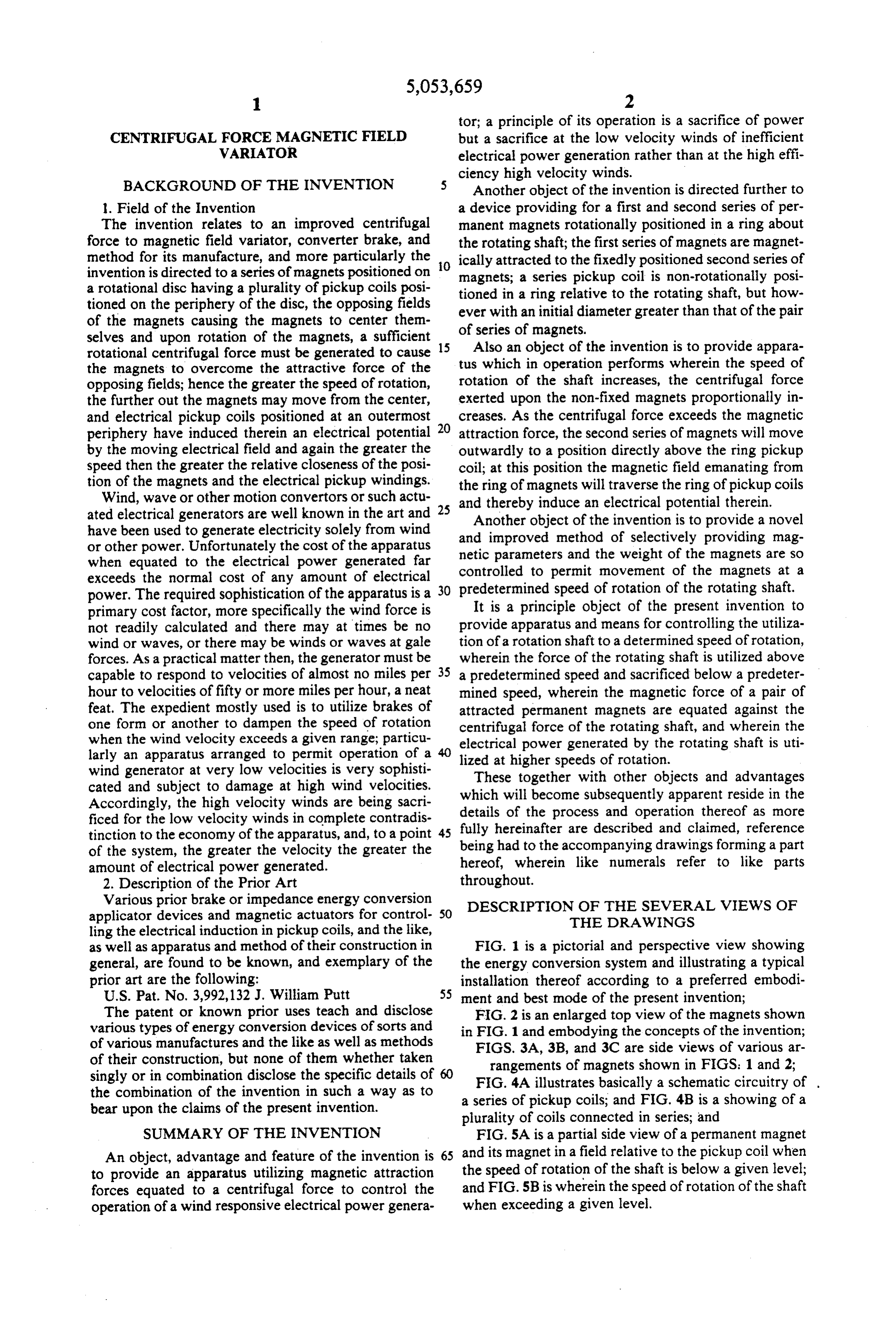
ling the electrical induction in pickup coils, and the like, as well as apparatus and method of their construction in FIG. 1 is a pictorial and perspective view showing general, are found to be known, and exemplary of the the energy conversion system and illustrating a typical prior art are the following: installation thereof according to a preferred embodi U.S. Pat. No. 3,992,132.J. William Putt 55 ment and best mode of the present invention; The patent or known prior uses teach and disclose FIG. 2 is an enlarged top view of the magnets shown various types of energy conversion devices of sorts and in FIG. 1 and embodying the concepts of the invention; of various manufactures and the like as well as methods FIGS. 3A, 3B, and 3C are side views of various ar of their construction, but none of them whether taken rangements of magnets shown in FIGS. 1 and 2; singly or in combination disclose the specific details of 60 FIG.
the combination of the invention in such a way as to a series 4A of illustrates basically a schematic circuitry of .
pickup coils; and FIG. 4B is a showing of a bear upon the claims of the present invention. plurality of coils connected in series; and SUMMARY OF THE INVENTION FIG. 5A is a partial side view of a permanent magnet An object, advantage and feature of the invention is 65 and its magnet in a field relative to the pickup coil when to provide an apparatus utilizing magnetic attraction the speed of rotation of the shaft is below a given level; forces equated to a centrifugal force to control the and FIG. 5B is wherein the speed of rotation of the shaft operation of a wind responsive electrical power genera when exceeding a given level.
Page 6
DESCRIPTION OF A PREFERRED The first series of magnets 20 magnetically attract the EMBODIMENT OF THE INVENTION second series of magnets 28, the attraction being suffi cient force to prevent the magnetic field thereof to
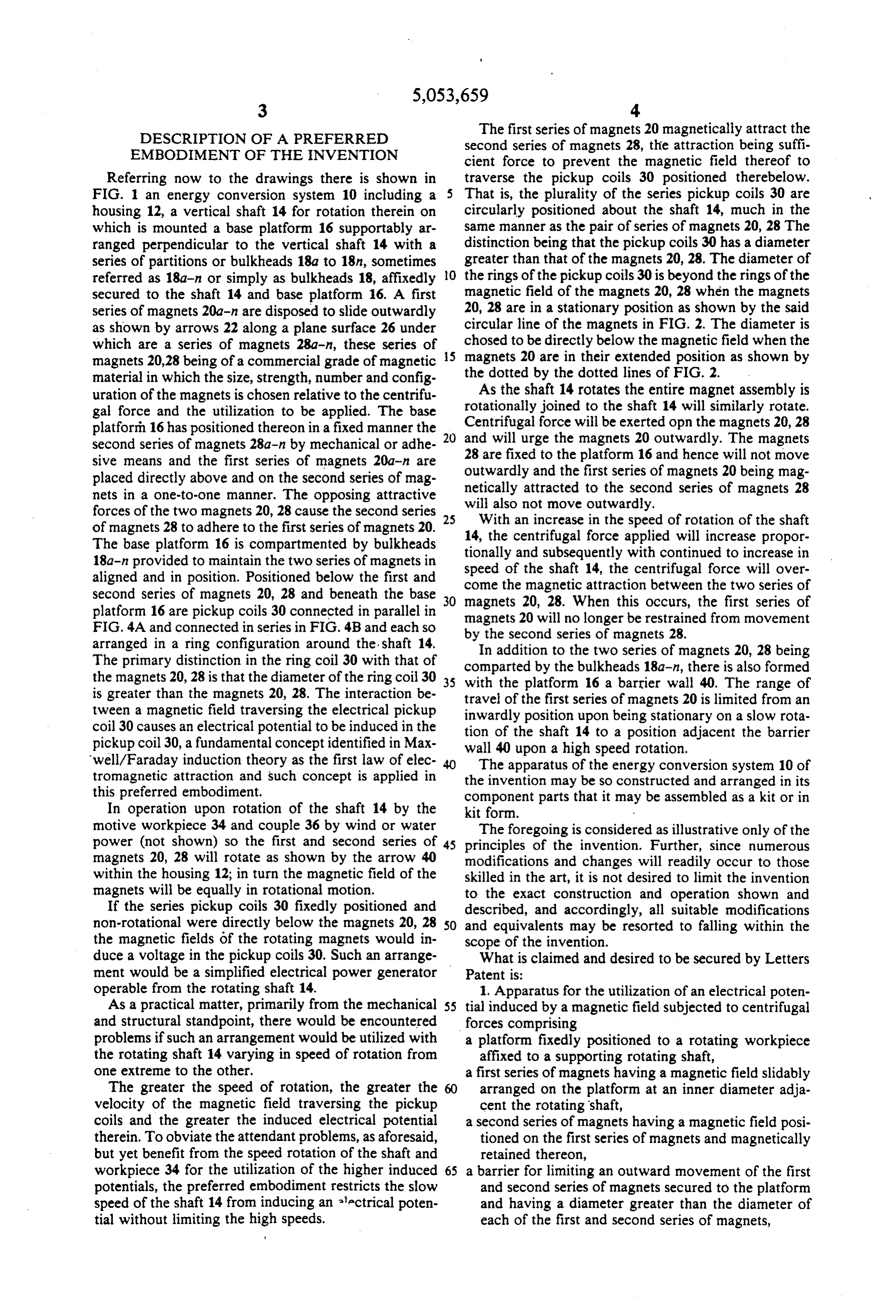
Referring now to the drawings there is shown in traverse the pickup coils 30 positioned therebelow. FIG. 1 an energy conversion system 10 including a That is, the plurality of the series pickup coils 30 are housing 12, a vertical shaft 14 for rotation therein on circularly positioned about the shaft 14, much in the which is mounted a base platform 16 supportably ar same manner as the pair of series of magnets 20, 28 The ranged perpendicular to the vertical shaft 14 with a distinction being that the pickup coils 30 has a diameter series of partitions or bulkheads 18a to 18n, sometimes greater than that of the magnets 20, 28. The diameter of referred as 18a-n or simply as bulkheads 18, affixedly O the rings of the pickup coils 30 is beyond the rings of the secured to the shaft 14 and base platform 16. A first magnetic field of the magnets 20, 28 when the magnets series of magnets 20a-n are disposed to slide outwardly 20, 28 are in a stationary position as shown by the said as shown by arrows 22 along a plane surface 26 under circular line of the magnets in FIG. 2. The diameter is which are a series of magnets 28a-n, these series of 5 chosed to be directly below the magnetic field when the magnets 20,28 being of a commercial grade of magnetic magnets 20 are in their extended position as shown by material in which the size, strength, number and config the dotted by the dotted lines of FIG. 2. As the shaft 14 rotates the entire magnet assembly is uration of the magnets is chosen relative to the centrifu rotationally gal force and the utilization to be applied. The base joined to the shaft 14 will similarly rotate. platforth 16 has positioned thereon in a fixed manner the and will urge thewill
Centrifugal force be exerted opn the magnets 20, 28 second series of magnets 28a-n by mechanical or adhe 28 are fixed to the platform 20 magnets outwardly. The magnets sive means and the first series of magnets 20a-n are outwardly and the first series16ofand hence will not move magnets 20 being mag placed directly above and on the second series of mag netically attracted to the second series of magnets 28 nets in a one-to-one manner. The opposing attractive forces of the two magnets 20, 28 cause the second series 25 willWith also not move outwardly.
an increase in the speed of rotation of the shaft of magnets 28 to adhere to the first series of magnets 20. 14, the centrifugal force applied will increase propor The base platform 16 is compartmented by bulkheads tionally and subsequently 18a-n provided to maintain the two series of magnets in speed of the shaft 14, thewith continued to increase in centrifugal force will over aligned and in position. Positioned below the first and come the magnetic attraction between the two series of second series of magnets 20, 28 and beneath the base 30 magnets 20, 28. When this occurs, the first series of platform 16 are pickup coils 30 connected in parallel in magnets 20 will no longer be restrained from movement FIG. 4A and connected in series in FIG. 4B and each so arranged in a ring configuration around the shaft 14. byIntheaddition second series of magnets 28. The primary distinction in the ring coil 30 with that of comparted by tothethe two series of magnets 20, 28 being bulkheads 18a-n, there is also formed the magnets 20, 28 is that the diameter of the ring coil 30 35 with the platform 16 a barrier wall 40. The range of is greater than the magnets 20, 28. The interaction be travel of the first series of magnets 20 is limited from an tween a magnetic field traversing the electrical pickup inwardly position upon being stationary on a slow rota coil 30 causes an electrical potential to be induced in the tion of the shaft 14 to a position adjacent the barrier pickup coil 30, a fundamental concept identified in Max wall 40 upon a high speed rotation.
well/Faraday induction theory as the first law of elec The apparatus of the energy conversion system 10 of tromagnetic attraction and such concept is applied in the invention may be so constructed and arranged in its this preferred embodiment. component parts that it may be assembled as a kit or in In operation upon rotation of the shaft 14 by the kit form. m motive workpiece 34 and couple 36 by wind or water The foregoing is considered as illustrative only of the power (not shown) so the first and second series of 45 principles of the invention. Further, since numerous magnets 20, 28 will rotate as shown by the arrow 40 modifications and changes will readily occur to those within the housing 12; in turn the magnetic field of the skilled in the art, it is not desired to limit the invention magnets will be equally in rotational motion. to the exact construction and operation shown and If the series pickup coils 30 fixedly positioned and described, and accordingly, all suitable modifications non-rotational were directly below the magnets 20, 28 50 and equivalents may be resorted to falling within the the magnetic fields of the rotating magnets would in scope of the invention.
duce a voltage in the pickup coils 30. Such an arrange What is claimed and desired to be secured by Letters ment would be a simplified electrical power generator Patent is:
operable from the rotating shaft 14. 1. Apparatus for the utilization of an electrical poten As a practical matter, primarily from the mechanical 55 tial induced by a magnetic field subjected to centrifugal and structural standpoint, there would be encountered forces comprising problems if such an arrangement would be utilized with a platform fixedly positioned to a rotating workpiece the rotating shaft 14 varying in speed of rotation from affixed to a supporting rotating shaft, one extreme to the other. a first series of magnets having a magnetic field slidably The greater the speed of rotation, the greater the arranged on the platform at an inner diameter adja velocity of the magnetic field traversing the pickup cent the rotating shaft, coils and the greater the induced electrical potential a second series of magnets having a magnetic field posi therein. To obviate the attendant problems, as aforesaid, tioned on the first series of magnets and magnetically but yet benefit from the speed rotation of the shaft and retained thereon, workpiece 34 for the utilization of the higher induced 65 a barrier for limiting an outward movement of the first potentials, the preferred embodiment restricts the slow and second series of magnets secured to the platform speed of the shaft 14 from inducing an 'ectrical poten and having a diameter greater than the diameter of tial without limiting the high speeds. each of the first and second series of magnets,
Page 7
pickup coil means fixedly positioned beneath the plat 3. The apparatus of claim 1 wherein the magnets of the first and second series are greater in number than form and having a diameter greater than the diameter said pickup coils.
of the first and second series of magnets but less than 4. The apparatus of claim 1 wherein the housing cy the diameter of the barrier, lindrical.
5. The apparatus of claim 1 wherein the series of the first series of magnets being forced outwardly to a magnets and pickup coils are cylindrically arranged and position impacting the barrier in response to centrifu the first series of magnets are retained by a spring to a first position adjacent the shaft.
gal force of the rotating workpiece exceeding the 1O 6. The apparatus of claim 1 wherein the coils are force of the magnetic field of attraction between the connected in series.
first and second series of magnets, and 7. The apparatus of claim 1 wherein the coils are the first series of magnets being extended to the mag connected in parallel.
8. The apparatus of claim 1 wherein the the barrier netic fields thereof to attain a vertical alignment with 15 wall is cylindrical.
the pickup coil means thereby inducing therein the 9. The apparatus of claim 1 wherein the shaft is verti electrical potential. cally disposed.
10. The apparatus of claim 1 wherein the series of 2. The apparatus of claim 1 wherein the apparatus is magnets are separated by a bulkhead.
in a housing.
Provenance
- Collection
- Patents citing this work
- Pages
- 7
- Method
- pdftotext (the PDF's own text layer) + pdftoppm 300dpi page scans
- Patent office record
- patents.google.com →
- Source
- Google Patents citing-documents table
- Assignee
- Denson Parker
- Inventors
- Denson Parker
- Published
- 1991-10-01
- Transcribed from
- patentimages.storage.googleapis.com →