patent · US4191902
Rotary electric machines
4 March 1980
Page 1 — bibliographic record
United States Patent (19) 11 4,191,902 Yarrow 45 Mar. 4, 1980
(54) ROTARY ELECTRIC MACHINES (56) References Cited
75 Inventor: Christopher J. Yarrow, Bradford, 3,335,348 8/1967 Gossel ................................ 310/68 X England 3,509,447 4/1970 Wharton ............................ 310/68 X 3,723,794 3/1973 Spisak et al. . ... 310/68 D 3,902,774 9/1975 Gronholm 0 0 000 so w8 e o a wo 310/68 X 73 Assignee: Lucas Industries Limited, Primary Examiner-Donovan F. Duggan Birmingham, England
(21) Appl. No.: 859,128 In a rotary electric machine having a winding and a rectifier arrangement which rotate in unison, the recti fier comprises a plurality of diodes each having a termi 22 Filed: Dec. 9, 1977 nal lug extending parallel to the rotor axis, and electri cal connections between the winding and rectifier ar 30 Foreign Application Priority Data rangement are provided by connectors which extend Dec. 11, 1976 GB United Kingdom ............... 51816/76 between the respective terminal lugs and locations on the winding which are generally diametrally opposite the lugs, whereby the combination of the centrifugal 51) Int. C.’............................................. HO2K11/00 forces on each lug and connector prevents distortion of 52 U.S. Cl. .................................... 310/68 D; 310/71 the lugs.
Page 2
Drawing sheet — no readable text.
Page 3
Drawing sheet — no readable text.
Page 4
winding 13 at a terminal point 24 thereon diametrically
ROTARY ELECTRIC MACHINES opposite that lug 20.
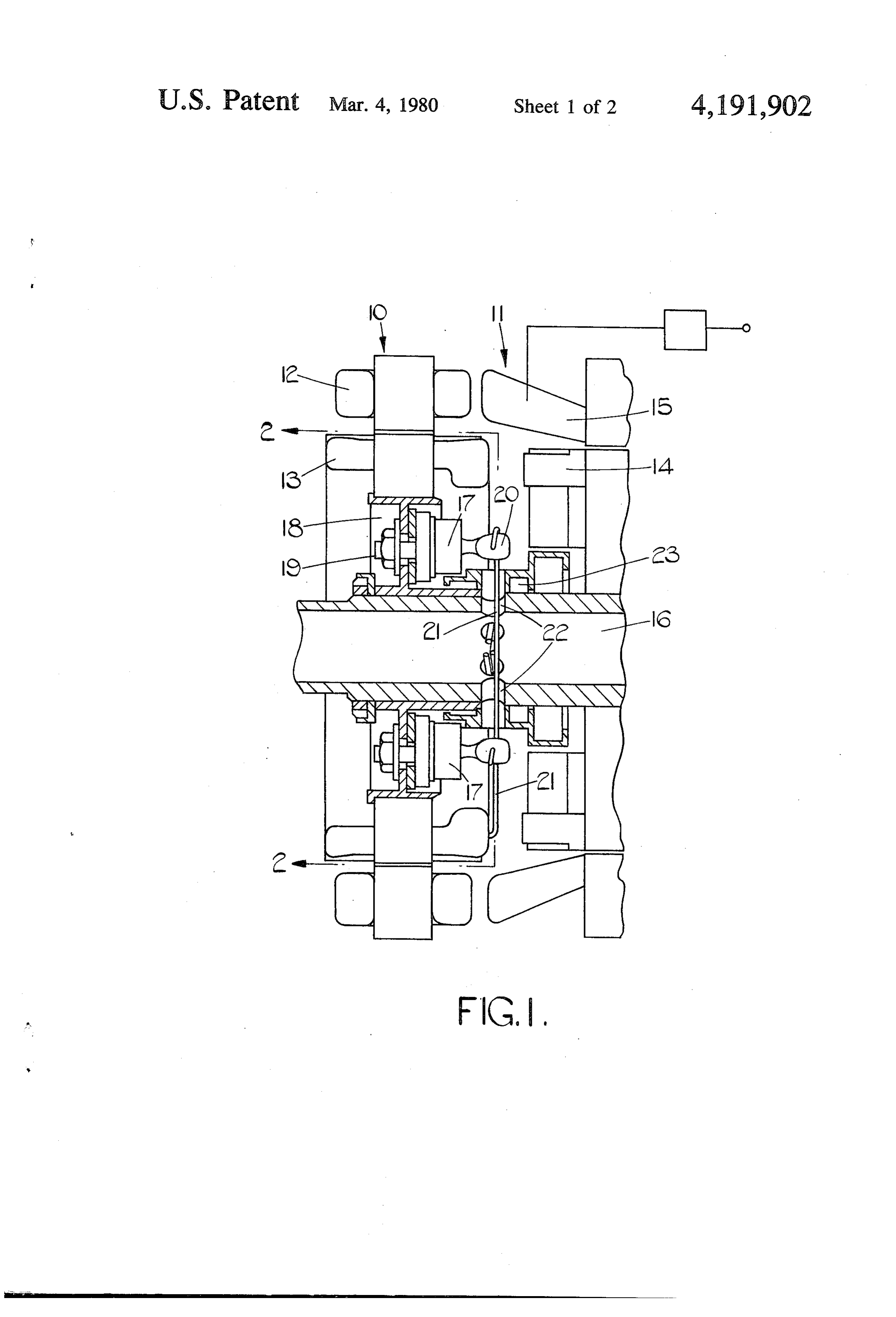
The diameters of the wires 21 and the radial distances
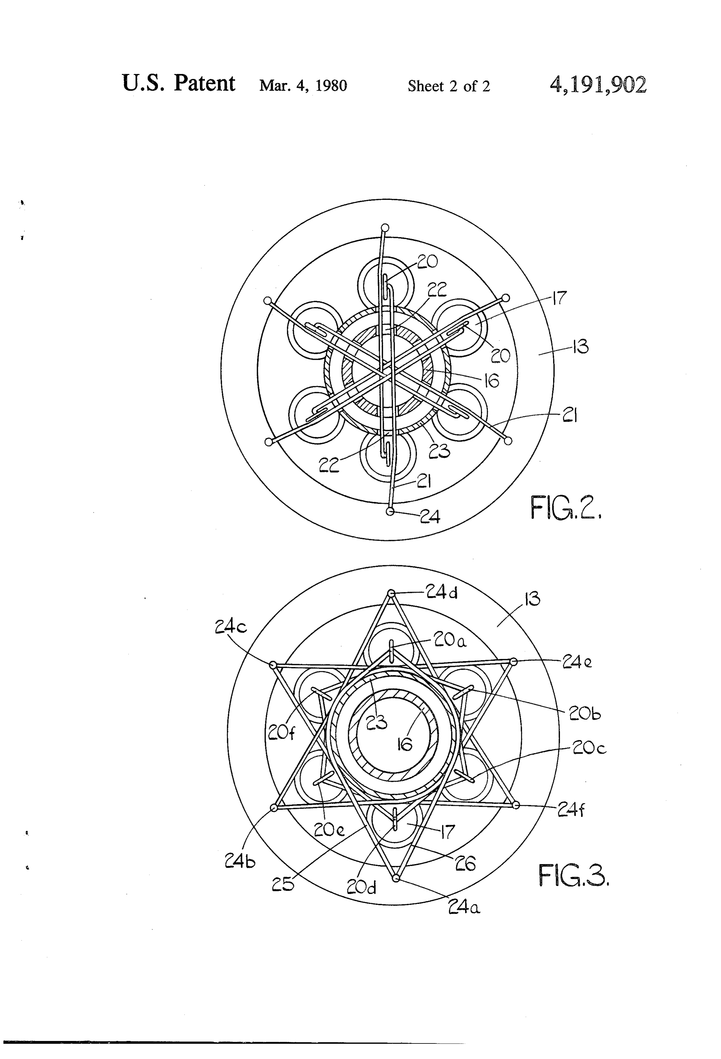
This invention relates to rotary electric machines, of the points 24 from the axis of the shaft 16, and hence It is known to provide electric generators having first 5 the lengths of the wires 21, are selected so that the sum and second alternators driven by a single shaft, the of the centrifugal forces acting on each lug 20 and the alternating output of a first one of the alternators being portion of the wire 21 adjacent that lug 20 on one side rectified by rectifiers which rotate with the shaft, and of the axis of the shaft 16 is balanced by the centrifugal the rectifier current then being used to provide a supply force acting on the portion of the wire 21 on the other to a rotating winding of the second alternator. For 10 side of the axis of the shaft 16. Tendency of the lugs 20 reasons of space the rectifiers are stud-mounted diodes to bend radially outwards under the effect of centrifugal with the axes of the mounting studs and terminal lugs forces is thus resisted by the tension in the wires 21, but parallel to the axis of the drive shaft.
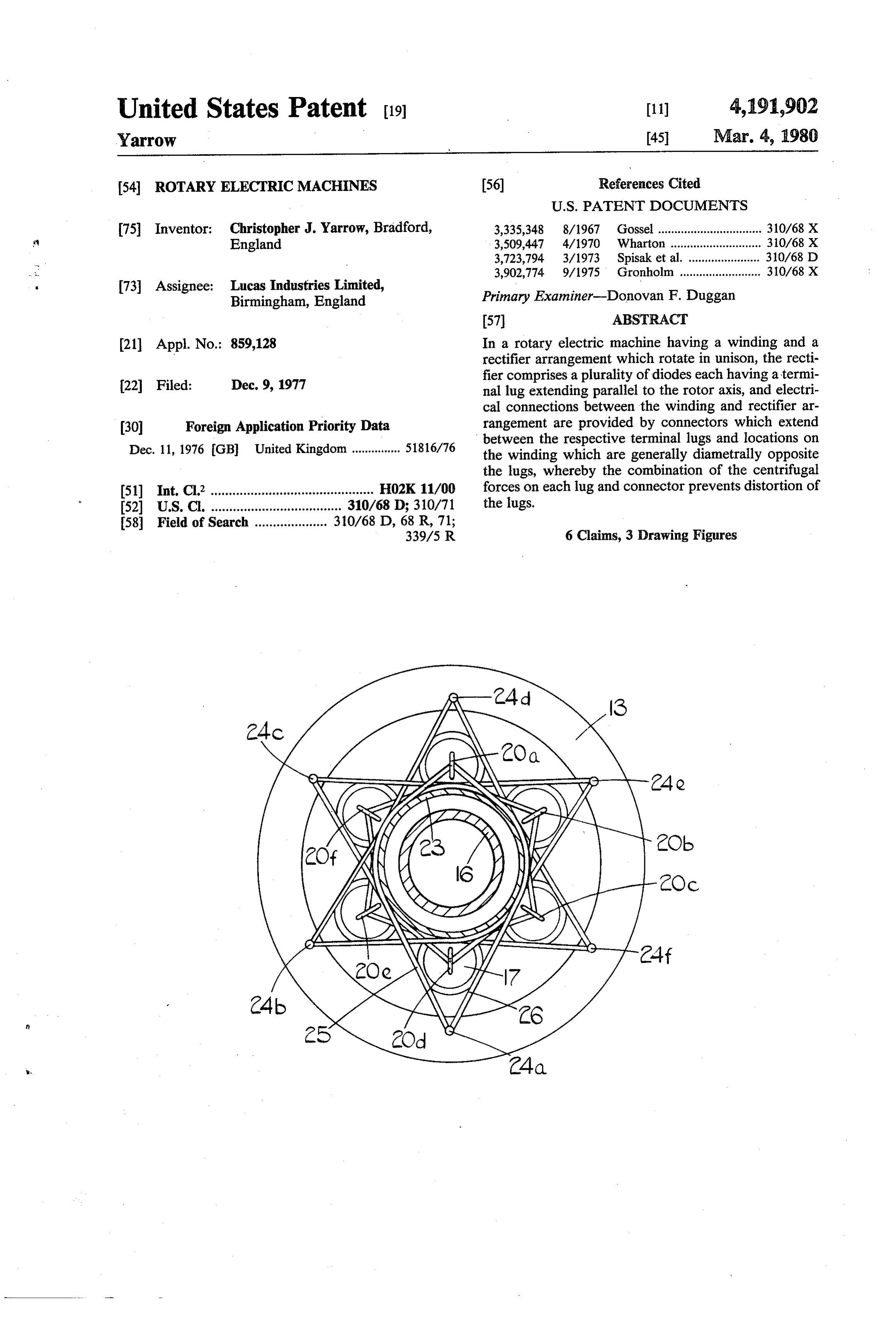
It has been proposed, in particular for generators to thisIntension is not applied to the terminal points 24. be carried on aircraft, to provide a two-pole rotor, and 15 20a is connected toembodiment the alternative shown in FIG.3 a lug a diametrically opposite terminal to rotate the generator at 24,000 rpm, the frequency of point the resultant output being 400 Hz. It has been found that around24aopposite by identical insulated wires 25, 26 which pass at these speeds centrifugal forces acting on the diodes through the shaftsides of the collar 23, instead of passing can cause damage thereto, particularly by distorting the wires 25, 26 are selected aslengths 16. The and diameters of the above described, so that the terminal lugs. 20 sum of the centrifugal forces acting on the lug 20a and
It is an object of the present invention to provide a the portions of the wires 25, 26 adjacent thereto are rotary electric machine of the foregoing type in which equal and opposite to the centrifugal forces acting on damage to the diodes from this cause may be reduced. the portions of the wires 25, 26 adjacent the terminal According to the invention a rotary electric machine point 24a. The provision of two wires 25, 26 has the includes a shaft, a winding mounted for rotation with 25 said shaft, a stud-mounted diode carried by said shaft for effect that a centrifugal force on the wire 25, acting to rotation therewith, a terminal lug of the diode extending urge the by lug 20a to the left, as seen in the drawing, is substantially parallel to the shaft axis, and an electric opposed urge the lug a centrifugal force on the wire 26 acting to 20a to the right.
connector between said lug and a location on said wind ing generally diametrally opposite said lug, the arrange 30 The lugs 20b, 20c, 20d, 20e, and 20f are similarly ment being such that, in use, the sum of the centrifugal connected to diametrically opposite terminal points 24b, forces acting on said lug and on a portion of said con 24c,I claim: 24d, 24e, and 24f nector adjacent thereto on one side of the shaft axis is substantially equal in magnitude and opposite in direc 1. A rotary electric machine including a shaft, a wind tion to the centrifugal force acting on the portion of said 35 ing mounted for rotation with said shaft, a stud connector on the other side of the shaft axis. In a pre mounted diode carried by said shaft for rotation there ferred embodiment there is provided a plurality of said with radially inwardly of said winding, a terminal lug of diodes and a plurality of said connectors between the the diode extending substantially parallel to the shaft lugs on respective ones of said diodes and generally axis, and an electric connector between said lug and a diametrally opposite portions of said winding. location on said winding generally diametrically oppo Embodiments of the invention will now be described site said lug, the arrangement being such that, in use, the by way of example only and with reference to the ac centrifugal forces acting on said lug and on a first por companying drawings in which: tion of said connector adjacent thereto on one side of FIG. 1, is a section through part of a brushless elec the shaft axis is opposed by the centrifugal force acting tric generator, 45 on a second portion of said connector on the other side FIG. 2, is a section on line 2-2 in FIG. 1, and of the shaft axis.
FIG. 3, is a view, corresponding to FIG. 2, and show 2. A machine as claimed in claim 1 in which said pair ing an alternative connector arrangement. of connectors extend round said shaft on opposite sides The generator of FIG. 1, is of a known type having thereof.
first and second alternators 10, 11. The alternator 10 has 50 3. A machine as claimed in claim 1 which includes a a stationary field winding 12 and a rotor winding 13. plurality of said diodes and a plurality of connectors The alternator 11 has a rotor winding 14 and a station between the lugs on respective ones of said diodes and ary winding 15. The windings 13, 14 are carried on a generally diametrally opposite portions of said winding. common shaft 16, of the generator. The alternator 10 is 4. A machine as claimed in claim 3 which includes a arranged so that when the winding 12 is separately 55 plurality of said diodes and plurality of pairs of connec excited and the shaft 16 is driven, the output of the tors between the lugs on respective ones of said diodes alternator 10 is a three-phase current. The output of the and generally diametrically opposite portions of said alternator 10 is supplied to the alternator 11 via a recti winding.
fier arrangement comprising six power-rectifying di 5. A machine as claimed in claim 1 in which said odes 17 mounted on a flange 18 forming part of the shaft 60 connector extends around the periphery of said shaft 16. between said lug and said winding location. The diodes 17 are stud-mounted so that the axes of 6. A machine as claimed in claim 1 in which the ar the studs 19 and of the terminal lugs 20 of the diodes rangement is such that said sum of the centrifugal forces extend parallel to the axis of the shaft 16. The respective on said lug and said first connector portion is substan lugs 20 are electrically connected to the winding 13 by 65 tially equal in magnitude and opposite in direction to insulated wires 21. Each of the wires 21 extends the centrifugal force acting on said second connector through apertures 22, in the shaft 16 and a surrounding portion.
collar 23, so that each of the lugs 20 is connected to the : 3 a sk
Provenance
- Collection
- Cited prior art
- Original PDF
- patentimages.storage.googleapis.com →
- Filed
- 1977-12-09
- Pages
- 4
- Method
- pdftotext (the PDF's own text layer) + pdftoppm 300dpi page scans
- Source
- Google Patents bibliographic record
- Granted
- 1980-03-04
- Inventors
- Christopher J. Yarrow; Lucas Industries Ltd
- Transcribed from
- patentimages.storage.googleapis.com →