patent · US4486675
Direct current magnetic motor
4 December 1984
Page 1 — bibliographic record
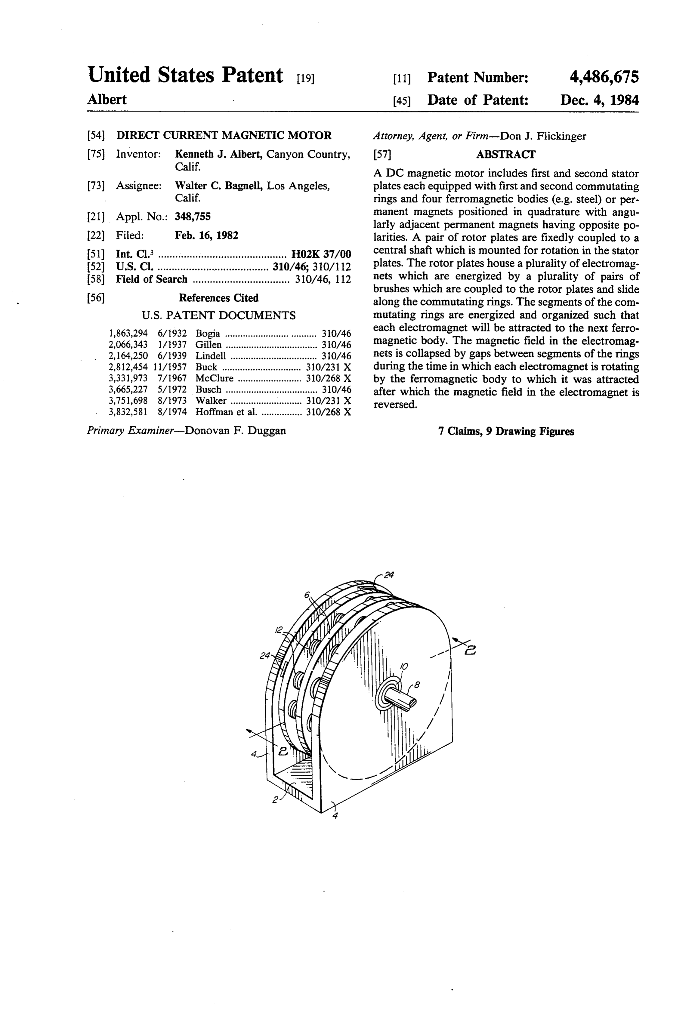
United States Patent (19) 11) Patent Number: 4,486,675 Albert 45) Date of Patent: Dec. 4, 1984 54 DIRECT CURRENT MAGNETIC MOTOR Attorney, Agent, or Firm-Don J. Flickinger 75 Inventor: Kenneth J. Albert, Canyon Country, (57) ABSTRACT Calif.
A DC magnetic motor includes first and second stator 73) Assignee: Walter C. Bagnell, Los Angeles, plates each equipped with first and second commutating Calif. rings and four ferromagnetic bodies (e.g. steel) or per (21) Appl. No.: 348,755 manent magnets positioned in quadrature with angu larly adjacent permanent magnets having opposite po 22 Filed: Feb. 16, 1982 larities. A pair of rotor plates are fixedly coupled to a 51) int. Cl. ............................................. HO2K 37/00 central shaft which is mounted for rotation in the stator 52 U.S. Cl. ....................................... 310/46; 310/112 plates. The rotor plates house a plurality of electromag 58) Field of Search .................................. 310/46, 112 nets which are energized by a plurality of pairs of
brushes which are coupled to the rotor plates and slide along the commutating rings. The segments of the com
1,863,294 6/1932 Bogia ................................... 310/46 each electromagnet will be attracted to the next ferro 2,066,343 1A1937 Gillen ..... ... 310/46 magnetic body. The magnetic field in the electromag 2,164,250 6/1939 Lindell .................................. 31.0/46 nets is collapsed by gaps between segments of the rings 2,812,454 1 1/1957 Buck ....... . 31.0/2.31 X during the time in which each electromagnet is rotating 3,331,973 7/1967 McClure 310/268 X by the ferromagnetic body to which it was attracted 3,665,227 5/1972 Busch .................................... 30/46 after which the magnetic field in the electromagnet is 3,751,698 8/1973 Walker ............... 310/23 X reversed.
Primary Examiner-Donovan F. Duggan 7 Claims, 9 Drawing Figures
Page 2
Drawing sheet — no readable text.
Page 3
Drawing sheet — no readable text.
Page 4
magnetic fields to produce the continuous motive
DIRECT CURRENT MAGNETIC MOTOR power.
BACKGROUND OF THE INVENTION SUMMARY OF THE INVENTION 1. Field of the Invention It is an object of the present invention to provide an This invention relates generally to direct current improved It is a
DC magnetic motor.
further object of the present invention to pro
(DC) magnet motors and, more particularly, to a mag vide a DC magnet netic motor system utilizing a plurality of ferromagnetic means on a stator motor plate which includes commutator for alternating the magnetic bodies (e.g. steel) on a stator which magnetically inter O fields of electromagnets housed act with a larger plurality of electromagnets on a rotor ery of a pair of rotor plates. proximate the periph to turn a shaft, the electromagnets being energized in a It is a still further object of the present invention to predetermined sequence by commutator means on the provide an apparatus for applying DC potentials of Stato.
2. Description of the Prior Art alternating polarity to the coil terminals of an electro 15 magnet.
It is well known that two magnetic poles of opposite According to a broad aspect of the invention, there is polarity will attract each other. Furthermore, subject to provided certain restrictions, two magnetic poles of similar polar least one astator direct current magnetic motor comprising at plate; at least one ferromagnetic body ity will repel each other with a force which is directly mounted on the stator plate; first and second commutat proportional to the product of the individual pole 20 ing rings, each including strengths, and inversely proportional to the square of mounted on the stator plate; aat plurality of segments the distance separating them. The force is affected by plurality of electromagnets mounted on the rotorplate; least one rotor a plate;
the permeability of the medium through which the and means coupled to the electromagnets and to the force acts which, for ordinary air, is nearly unity. rings for sequentially producing in the electromagnets a It is also well known that if any electric current is 25 first magnetic field therein, collapsing the first magnetic passed through a coil which is wrapped around a ferro field, and reversing the magnetic field. magnetic core, the core will exhibit magnet properties According to a further aspect of the invention, there in accordance with the direction of current flow. That is provided a direct current magnetic motor comprising is, the magnetic poles of the core may be reversed by 30 a pair of stator plates; a pair of rotor plates mounted for reversing the direction of current flow in the coil rotation; a plurality of ferromagnetic bodies mounted Permanent magnets and electromagnets are en on each of the stator plates; a pair of commutating rings ployed in motors and their forces of attraction and re each including a plurality of segments mounted on each pulsion utilized to impose a force upon the motor's of the stator plates; a plurality of electromagnets armature to cause rotation or to cause the armature to mounted near the peripheral of the rotor plates; and be linearly displaced. In the case of a rotating armature, 35 means coupled to the rotor plates and engaging the a problem must be overcome which may be simply commutating rings and coupled to the plurality of elec described as follows. Assume that first and second bar tromagnets for energizing each of the electromagnets to magnets, each having a north pole and a south pole, are first be attracted to one of the ferromagnetic bodies for mounted for rotation adjacent each other. The bar mag then collapsing the magnetic field in the electromagnet nets will align themselves parallel to each other due to as it rotates by the permanent magnetic to which it was the substantially equal forces of repulsion between like previously attracted, and for reversing the magnetic poles. If the force of repulsion between a first pair of field of the electromagnet.
like poles were converted to a force of attraction, as by According to a still further aspect of the invention, insertion of a ferromagnetic material therebetween, the 45 there is provided an apparatus for applying different first pair of poles would rotate towards each other potentials to a utilization device comprising a seg while the remaining pair of like poles would rotate mented ring wherein each segment comprises an electri away from each other. Thus, the forces of attraction cally conductive ramp portion and a non-conductive and repulsion have been utilized to create rotation. step portion; means coupled to each of the ramp por Unfortunately, when the first pair of poles (which now 50 tions for applying a DC potential thereto, the potentials may be considered opposite poles since they are at applied to adjacent ramp portions being different; car tracted to each other) arrive at a position most proxi rier means mounted over the ring; and an electrically mate each other, the system will lock up and, unless conductive plunger resiliently mounted within the car additional steps are taken, further rotation is impossible. rier and coupled to the utilization device, the plunger The same problem exists in the case of an electromag 55 sequentially engaging each of the conductive ramp net rotating past a ferromagnetic body (such as steel) or portions when there is relative movement between the a permanent magnet of a polarity which attracts the ring and the carrier in a predetermined direction. electromagnet. When the electromagnet reaches a posi The above and other objects, features and advantages tion most proximate the ferromagnetic body or the of the present invention will be apparent from the fol permanent magnet, the forces of attraction will be the 60 lowing detailed description taken in conjunction with strongest and will resist further rotation. the accompanying drawings, in which: Referring again to motors employing permanent BRIEF DESCRIPTION OF THE DRAWINGS magnets and electromagnets, it has been necessary to provide additional magnetic interaction at the lock-up FIG. 1 is an isometric view of a DC magnetic motor points to achieve continuous and uninterrupted rota 65 in accordance with a first embodiment of the present tion. In some cases, this is accomplished using elaborate invention;
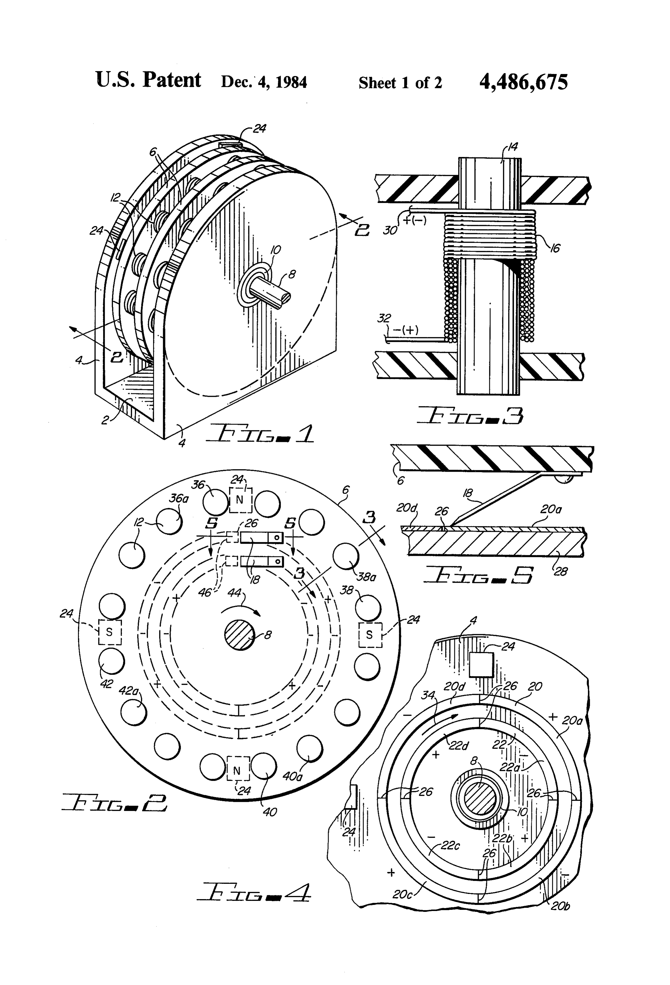
and complex switching means to control the energiza FIG. 2 is a cross-sectional view of the motor shown tion of the electromagnets and the orientation of the in FIG. 1 taken along line 2-2;
Page 5
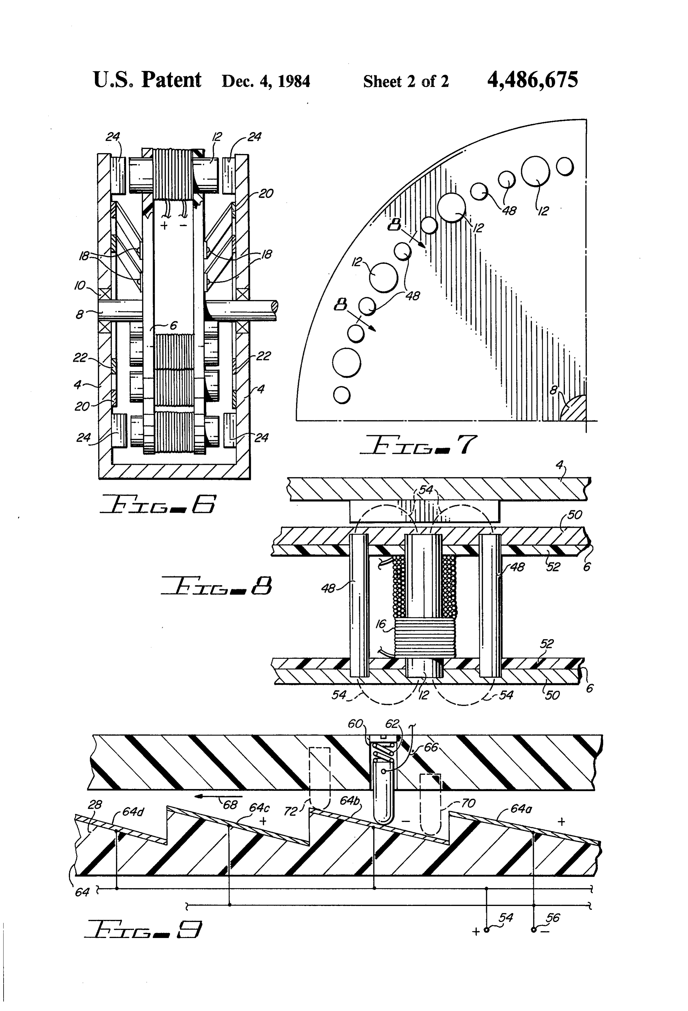
FIG. 3 is a partial cross-sectional view of one of the be coupled to a positive potential while segments 20b, sixteen electromagnets positioned within the rotor 20d, 22a and 22c may be coupled to a negative potential. plates of the motor shown in FIG. 1; The sources of opposite electric potentials may simply FIG. 4 is a cross-sectional view illustrating commu be DC batteries; however, a variety of circuit means tating rings and ferromagnetic bodies or permanent would be obvious to the skilled practitioner for cou magnets fixed to the interior surface of a stator plate pling potentials of the required polarity to the appropri within the motor shown in FIG. 1; ate segments of the commutator rings 20 and 22. FIG. 5 is a cross-sectional view taken along line 5-5 Between each angularly adjacent segment of rings 20 of FIG. 2 illustrating one of the motor's brushes and 22 (for example, 20d and 20a) there is a gap 26 mounted on a rotor plate and sliding along a commutat O shown in more detail in FIG. 5. While each of the seg ing. ring on a stator plate; ments is made of an electrically conductive material, it FIG. 6 is a cross-sectional view of the DC magnetic should be clear that the material 28 beneath the rings motor shown in FIG. 1; and in contact therewith, must be a non-conducting FIG. 7 is a cross-sectional view of a portion of a rotor material so as not to short the ring segments together. plate within a DC magnetic motor in accordance with a 15 Thus, as brush 18 slides from segment 20d to segment second embodiment of the present invention; 20a, there will be a reversal in potential of the brush 18, FIG. 8 is a partial cross-sectional view of one of the and just prior to the reversal (while the tip of brush 18 electromagnets housed within the rotor plate of FIG.7; is over gap 26) there will be no potential applied to and brush 18.
Referring again to FIG. 3, coil 16 wrapped around
FIG. 9 is a cross-sectional view of an alternate stator 20 commutator and rotor brush assembly. ferromagnetic core 14 has two ends 30 and 32 which are DESCRIPTION OF THE PREFERRED coupled to first and second brushes of a pair of brushes EMBODIMENTS 18. If, for example, the first brush is contacting segment 22d of ring 22 and the second brush is contacting seg
FIGS. 1 and 6 are isometric and cross-sectional 25 ment 20d of ring 20, then a positive potential will be views, respectively, of a DC magnetic motor embody applied to coil end 30 while a negative potential is ap ing the teachings of the present invention. A stator plied to coil end 32. As a result, current will flow in coil comprises a base member 2 and first and second up 16 from terminal 30 to terminal 32 producing a magnet wardly extending stator plates 4, each of which has an field in core 14 of a first polarity. When the first and upward extending semicircular periphery. A pair of 30 second brushes reach gap 26 as a result of traveling in circular rotor plates 6 are fixedly coupled to a central the direction shown by arrow 34 in FIG. 4, no current shaft 8 which is in turn mounted for rotation within will flow in coil 16 since the potential difference be stator plates 4 by means of bearing assemblies 10. Rotor tween coil ends 30 and 32 has been removed thus de plates 6 have positioned therein a plurality (e.g. sixteen) stroying the magnetic field. Finally, when the first and of electromagnets 12, each of which comprise a ferro 35 second brushes reach segments 22a and 20a, respec magnetic core 14 and a coil 16 wrapped around core 14 tively, coil end 30 will be coupled to a negative poten for carrying electric current as is more specifically tial while coil end 32 is coupled to a positive potential. shown in FIG. 3. Obviously, rotor plates 6 must be As a result, current will again flow in coil 16 but this non-ferromagnetic so as not to short out the magnetic time from coil end 32 to coil end 30. Core 14 will again circuit. Also coupled to rotor plates 6 are a plurality of 40 be magnetized but this time the polarity of the magnetic pairs of current conducting brushes 18 (typically four field will be reversed.
pairs) only two pairs of which are shown in FIG. 6. Having explained the individual principles upon Each brush 18 is rigidly mounted to a rotor plate 6 and which the present invention is based, the operation of has a contact end which slides along one of two com the motor will now be discussed. FIG. 2 illustrates the mutating rings 20 and 22 on the interior surface of the 45 relative positions of electromagnets 12, ferromagnetic adjacent stator plate 4. Also coupled to the interior bodies 24, commutator rings 20 and 22, gaps 26, and a surface of each stator plate 4 are four bodies of ferro single pair of brushes 18. If permanent magnets are magnetic material (e.g. steel) or permanet magnets 24 employed, assume that the upper and lower permanent positioned in quadrature; i.e., spaced 90' around each magnets exhibit a north polarity and that the left and stator plate 4. If permanent magnets 24 are employed, 50 right permanent magnets exhibit a south polarity. Fur the magnets are chosen such that diametrically opposed ther assume that the rotor plate 6 is turning in a clock permanent magnets 24 on each stator plate 4 present wise direction as indicated by arrow 44. Dotted por similar pole face polarities to electromagnets 12 while tions 46 of brushes 18 indicate the positions of the angularly adjacent permanent magnets 24 on each stator brushes 18 just prior to reaching gap 26. In this position, plate 4 present opposite pole face polarities. Further 55 electromagnets 36 and 40 are energized by the poten more, permanent magnets 24 occupying corresponding tials on rings 20 and 22 via brushes 18 to exhibit a south positions in the first and second stator plates 4 must be magnetic pole while electromagnets 38 and 42 are ener of opposite polarities since they face opposite poles of gized by the potentials on rings 20 and 22 via brushes 18 the electromagnets 12. to exhibit a north magnetic pole. Electromagnets 36,38, FIG. 4 illustrates more clearly the interior surface of 60 40 and 42 are attracted towards ferromagnetic bodies 24 each stator plate 4. As can be seen, each of the rings 20 in a clockwise direction. When electromagnets 36, 38, and 22 is divided into four quadrature segments (20a, 40 and 42 reach positions most adjacent permanent 20b, 20c, 20d and 22a, 22b, 22c, 22d, respectively) with magnets 24, the contacts of brushes 18 will reach gap 26 angularly adjacent segments in each ring coupled to destroying the magnetic fields in electromagnets 36, 38, electric potentials of opposite polarity. Furthermore, 65 40 and 42. This permits electromagnets 36, 38, 40 and 42 radially adjacent segments of commutating rings 20 and to easily rotate past bodies 24 at which point the 22 are also coupled to potentials of opposite polarity. contacts of brushes 18 make contact with the next angu Thus, for example, segments 20a, 20c, 22b and 22d may larly adjacent segments of rings 20 and 22. This reverses
Page 6
the magnet fields in electromagnets 36, 38, 40 and 42; corresponds to that time when its associated electro i.e., electromagnets 36 and 40 exhibit a north magnetic magnets are passing by the permanent magnets on the pole while electromagnets 38 and 42 exhibit a south stator plates 4.
magnetic pole. If bodies 24 are permanent magnets with The above description of preferred embodiments is the polarities described above, then electromagnets 36, 5 given by way of example only. Various changes and 38, 40 and 42 will be repelled in a clockwise fashion. If modifications to the embodiments herein chosen for bodies 24 are not permanent magnets and there is no purposes of illustration will readily occur to those repelling force, the flywheel action of the rotating sta skilled in the art. To the extent that such modifications tor is sufficient to overcome any tendency to lock up. and variations do not depart from the spirit of the inven Furthermore, electromagnets 36, 38, 40 and 42 have O tion, they are intended to be included within the scope moved sufficiently past bodies 24 to render the forces of thereof which is assessed only by a fair interpretation of attraction between electromagnets 36a, 38a, 40a, and the following claims.
42a controlling. This magnetic pole reversal procedure Having fully described and disclosed the present is repeated each time brushes 18 cross a gap 26; i.e., first invention in such clear and concise terms as to enable the magnetic field is collapsed and then reproduced 15 those skilled in the art to understand and practice the with opposite poles. Each of the remaining three sets of same, the invention claimed is:
quadrature electromagnets undergo a similar pole re 1. A direct current magnetic motor comprising: versal process via a separate pair of brushes 18 each (A) a pair of stator plates disposed parallel to and time the brushes reach a gap 26. The end result is effi aligned with one another; cient rotation of rotor plates 6 and therefore, shaft 8 to 20 (B) a plurality of permanent magnets mounted on produce high torque motive power. inside faces of each of said stator plates such that FIG. 7 and 8 illustrate an alternate rotor/electromag diametrically opposed permanent magnets on each net assembly suitable for use in the inventive DC mag stator plate are of the same polarity, circumferen netic motor. In order to increase magnetic flux density tially adjacent permanent magnets on each stator and therefore the forces of attraction and repulsion, 25 plate are of opposite polarity, and facing magnets each main electromagnetic core 12 has associated there are of opposite polarity; with two secondary cores 48. Furthermore, each rotor (C) a rotor assembly including: plate 6 now comprises a ferromagnetic layer 50 and a 1. a pair of rotor plates; non-ferromagnetic layer 52. The flux path through core 2. a central shaft fixedly coupled to said pair of 12, layers 50, ferromagnetic body 24 and secondary rotor plates and mounted for rotation in said pair cores 48 is illustrated by dotted lines 54. As a result of of stator plates; and the increased magnetic forces which are due to the 3. a plurality of electromagnets mounted proximate greater flux density, the torque of the motor is in the periphery of said pair of rotor plates; creased. (D) a concentric pair of segmented commutator rings FIG. 9 illustrates an alternate commutator/brush 35 mounted on each of said stator plates, each of said assembly. Each brush consists of a conductive plunger segments in each of said pair of commutator rings 58 mounted within a chamber 60 in rotor plate 6 and being separated from circumferentially adjacent coupled to appropriate electromagnets via wire 66. The segments by a non-conductive gap; plunger is biased by spring 62 into contact with the (E) at least one pair of electrically conductive brush commutating segments of a ring 64. For the purposes of 40 means carried by said rotor plates, each brush explanation, ring 64 is linearly represented although it means of said pair slideably engaging one of said should be clear that in practice it will be circular and segmented commutator rings; that conductive segments 64a, 64b, 64c, and 64d are (F) said brush means being coupled to said plurality actually 90' circular segments. As was the case previ of electromagnets for:
ously, material 28 is a non-conductive material, and 45 1. first, energizing at least one of said plurality of each adjacent segment is coupled to sources of opposite electromagnets to be attracted to one facing pair potential, for example, at terminals 54 and 56. As of said plurality of permanent magnets; shown, each segment includes a ramp portion and a step 2. second, collapsing the magnetic field of said at ortion. The step portions are positioned as were gaps 26 least one of said plurality of electromagnets as it in FIGS. 2 and 4. 50 rotates by said one facing pair of magnets and as If it is assumed that rotor plate 6 is moving to the left said brush means impinges non-conductive gaps as indicated by arrow 68 while slip ring 64 remains in said commutator rings; and stationary, plunger 58 will contact each conductive 3. third, energizing said at least one of said plurality segment, for example 64b, at a low point on the ramp as of electromagnets to be repulsed from said one indicated by the dotted representation 70 of plunger 58. 55 facing pair of said plurality of permanent mag Plunger 58 will slide along the segment until it reaches ets.
the uppermost point indicated by dotted representation 2. The direct current motor of claim 1 in which said 72. All during this time, a negative potential has been plurality of permanent magnets comprises four perma applied to the electromagnet terminals coupled to nent magnets positioned in quadrature on each of said plunger 58. As plunger continued its movement to the 60 pair of said stator plates.
left, it will fall off segment 64b. After a brief period of 3. The direct current motor of claim 1 in which said time during which plunger 58 is falling, it will contact plurality of electromagnets comprises sixteen electro segment 64c. During the time in which plunger 58 is magnets mounted on said pair of rotor plates, said elec falling, no current flows in its associated electromagnet tromagnets being selectively coupled to four pairs of coils and the magnetic fields therein collapse. When 65 said brush means.
plunger 58 contacts segment 64c, magnetic fields of 4. The direct current motor of claim 3 wherein each opposite polarity will be produced in the plunger's asso of said segments comprises a conductive ramp portion ciated electromagnets. The fall time of the plunger and a non-conductive step portion.
Page 7
6. The direct current motor of claim 1 in which each 5. The direct current motor of claim 4 in which each rotor plate is made of a non-ferromagnetic material. of said electrically conductive brushes comprises a 7. The direct current motor of claim 1 in which each rotor plate comprises a first layer of ferromagnetic ma plunger which is resiliently mounted within one of said 5 terial and a second layer of non-ferromagnetic material. rotor plates. k is is k k
Provenance
- Collection
- Cited prior art
- Original PDF
- patentimages.storage.googleapis.com →
- Filed
- 1982-02-16
- Pages
- 7
- Method
- pdftotext (the PDF's own text layer) + pdftoppm 300dpi page scans
- Source
- Google Patents bibliographic record
- Granted
- 1984-12-04
- Inventors
- Kenneth J. Albert
- Transcribed from
- patentimages.storage.googleapis.com →