patent · US3792295
Electromagnetic drive system
12 February 1974
Page 1 — bibliographic record
United States Patent (19) [11] 3,792,295 Garbi (45) Feb. 12, 1974 54 ELECTROMAGNETC DRIVE SYSTEM Primary Examiner-D. F. Duggan 76 Inventor: Frank Garbi, 48-21 40th St., Long
Island City, N.Y. 11 104 57 ABSTRACT 22 Filed: May 2, 1972 A machine for generating compressive energy from 21 Appl. No.: 249,560 kinetic energy, comprising a plurality of weights mounted for rotation on a shaft which is disposed at 52 U.S. Cl...................................... 310/46,310/82 an angle with respect to the axis of rotation. The shaft, 51 . Int. Cl....................................................... HO2k and the weights mounted thereon, are driven about
the axis of rotation by an electromagnetic drive com prising a segmented annular electromagnet, each seg 310/157, 75, 67, 46 ment of which is energized in advance of a magneti 56 References Cited cally sensitive element on the shaft to rotate the ele
UNITED STATES PATENTS
ment, shaft and the weights about the axis. By suitable crankshaft linkage, the rotational motion is transmit
R22,549 9/1944. Plensler.... ... . . . . . . . . . . . . 310/82 ted to linear motion of pistons which yield the com 2,378,668 6/1945 Vickers................................. 310/46 pressive energy to be generated. 3,595, 103 7, 1971 Wildhaber............................ 741800 6 Claims, 5 Drawing Figures
Page 2
Drawing sheet — no readable text.
Page 3
Drawing sheet — no readable text.
Page 4
Drawing sheet — no readable text.
Page 5
ELECTROMAGNETIC DRIVE SYSTEM Segmented electromagnet 20 is mounted in a collar. 24 supported on base 18 by a plurality of wheels 26
BACKGROUND OF THE INVENTION which permit collar 24 to rotate axially. A portion of The invention arises from the need to convert rela the circumference of collar 24 is provided with gear tively moderate but continuous quantities of electrical teeth 28 and is in engagement with a shaft-mounted energy into kinetic and thence into compressive energy worm 30. Worm shaft 32, mounted on base 18, is pro capable of exerting relatively large forces for certain vided with a with handle 34 to permit the worm to rotate in durations of time. The invention is intended for large engagement position of collar gear section 28 whereby the annular 24 and segmented electromagnet 20 scale use wherein the dimensions of sizes and weight O are such that very large amounts of kinetic energy are may be adjusted.
Extending upwardly through and within segmented stored in the high speed rotation of the weights, ready electromagnet to be extracted in linear motion of compression piston to the said axis20 is and disposed at an angle with respect a shaft 36 having a magnetic element pumps.
38 mounted thereon in close proximity to the inner an
SUMMARY OF THE INVENTION 15 nular surface of segmented electromagnet 20. Shaft 36 The present invention comprises an electromagnetic is supported from below by a knuckle joint support 40 drive for a system of extended weights whereby the and is supported near its upper end by a roller follower weights are rotated at substantial speeds, yielding large 42 which rides against an annular horizontal track 44 amounts of kinetic energy which may be tapped by a magneticinelement secured platform 16. The entire assembly of shaft 36, 38 and roller follower 42 rotate as a suitable crankshaft linkage which connects to pump unit about a vertical pistons. The electromagnetic drive consists of a seg axis of annular track axis 44 of rotation which is also the and annular segmented elec mented annular electromagnet, each segment of which tromagnet 20. The juncture between is energized in front of an advancing magnetic element. shaft 36 and knuckle joint support 40the is bottom end of also on the axis
The magnetic element is part of a primary crank system 25 of rotation as is a crankshaft 46 which is connected to having means to restrict its motion to rotation about an and extends below knuckle joint support 40. axis. Such rotation is effected by continuing attraction of the magnetic element as it advances about the elec 50.Secured While to shaft 36 are a plurality of weights 48 and two weights are shown in the drawing, it is tromagnet. clear that any number of weights greater than one may Rotational motion about the axis includes a system of weights extended from the axis whereby substantial be provided although care must be taken that they counterbalance each other within the limits discussed amounts of kinetic energy and inertia are generated.
A secondary crank system converts the rotational herein. In particular, at least one weight 48 should ex tend on the same side of shaft 36 as does roller follower motion to reciprocating linear motion of pump pistons 42, this being this side of the shaft which faces away which may be used in any suitable manner. 35 from the axis of rotation. Weight 48 should be greater BRIEF DESCRIPTION OF THE DRAWING than weight 50 which lies on the opposite side of shaft 36. The weight differential between weights 48 and 50
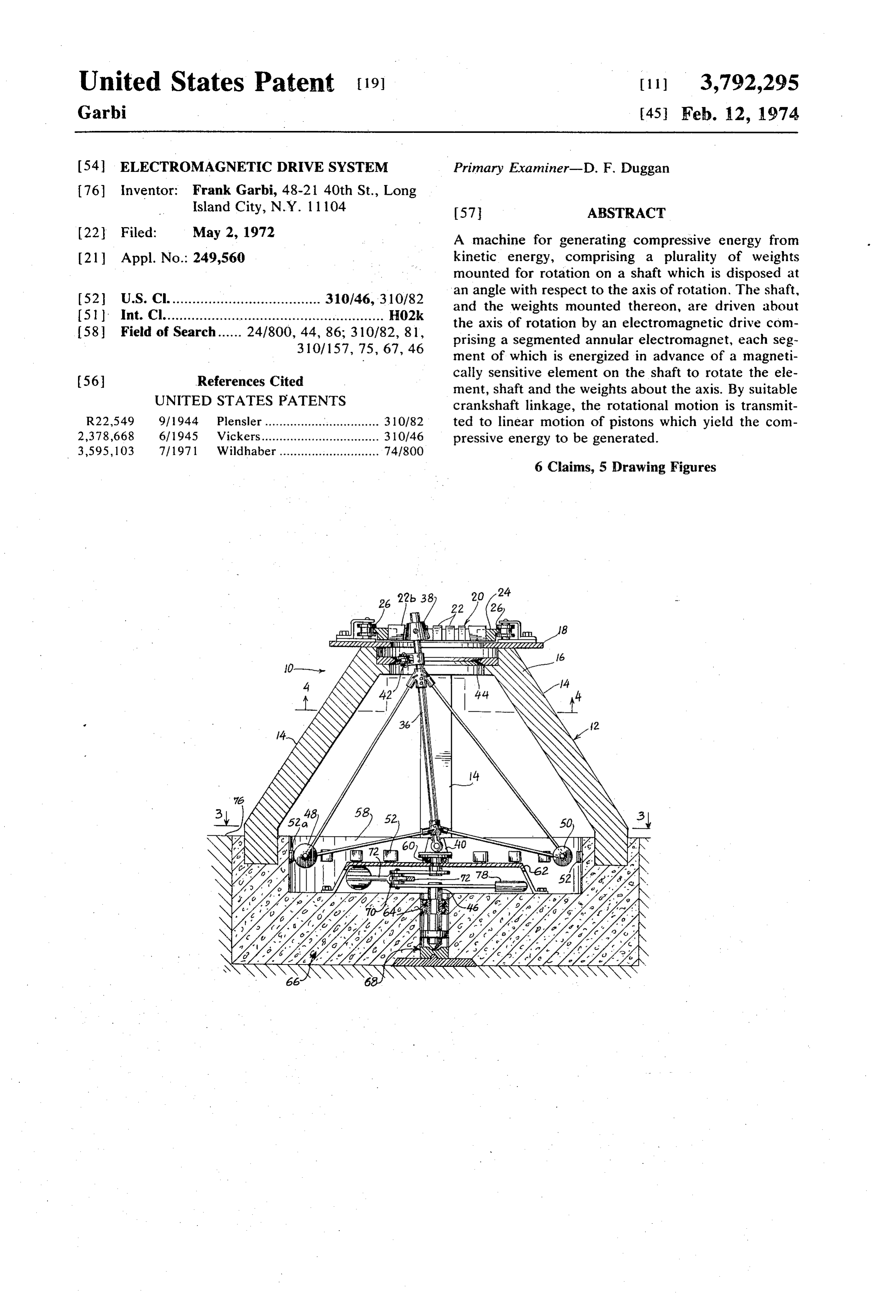
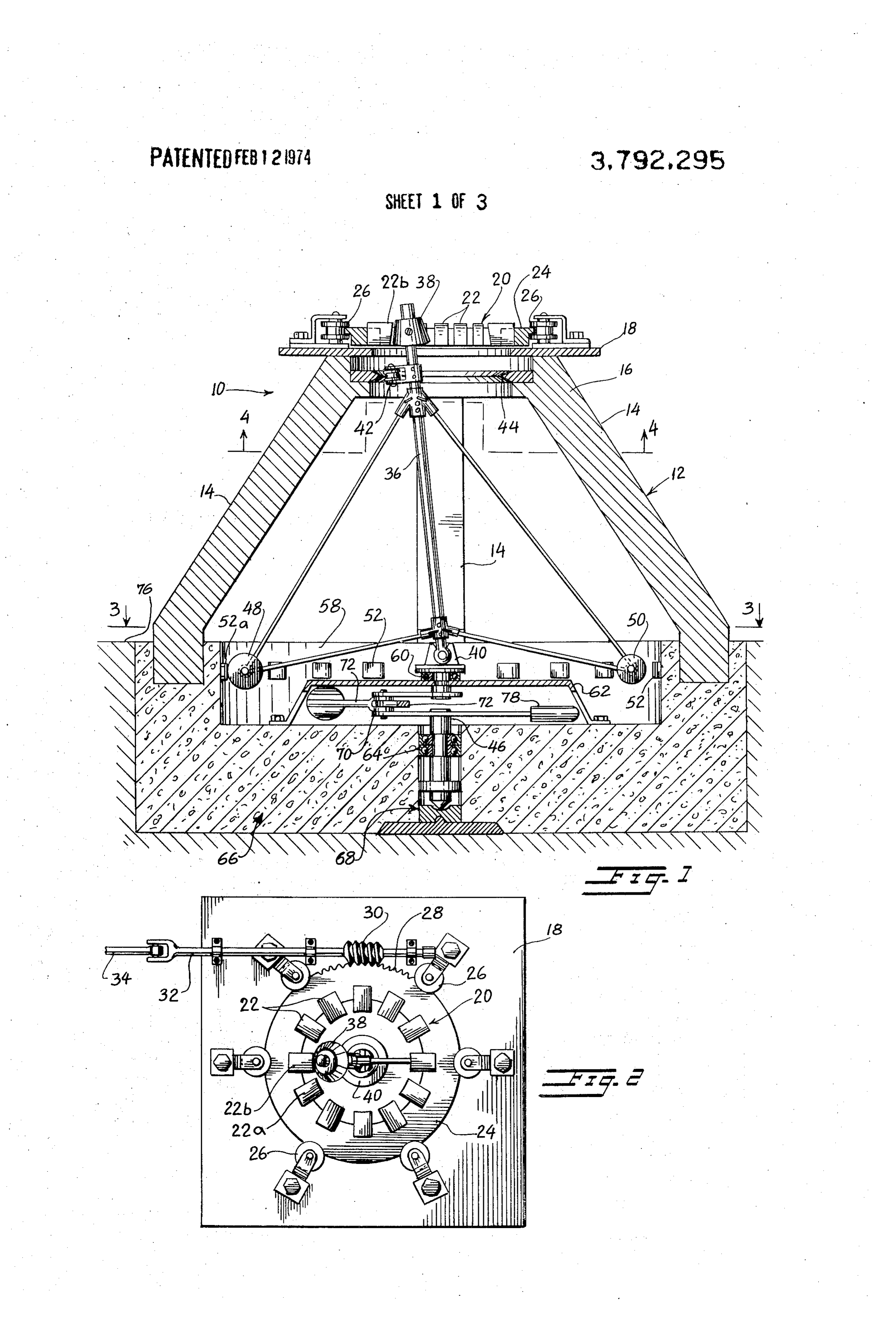
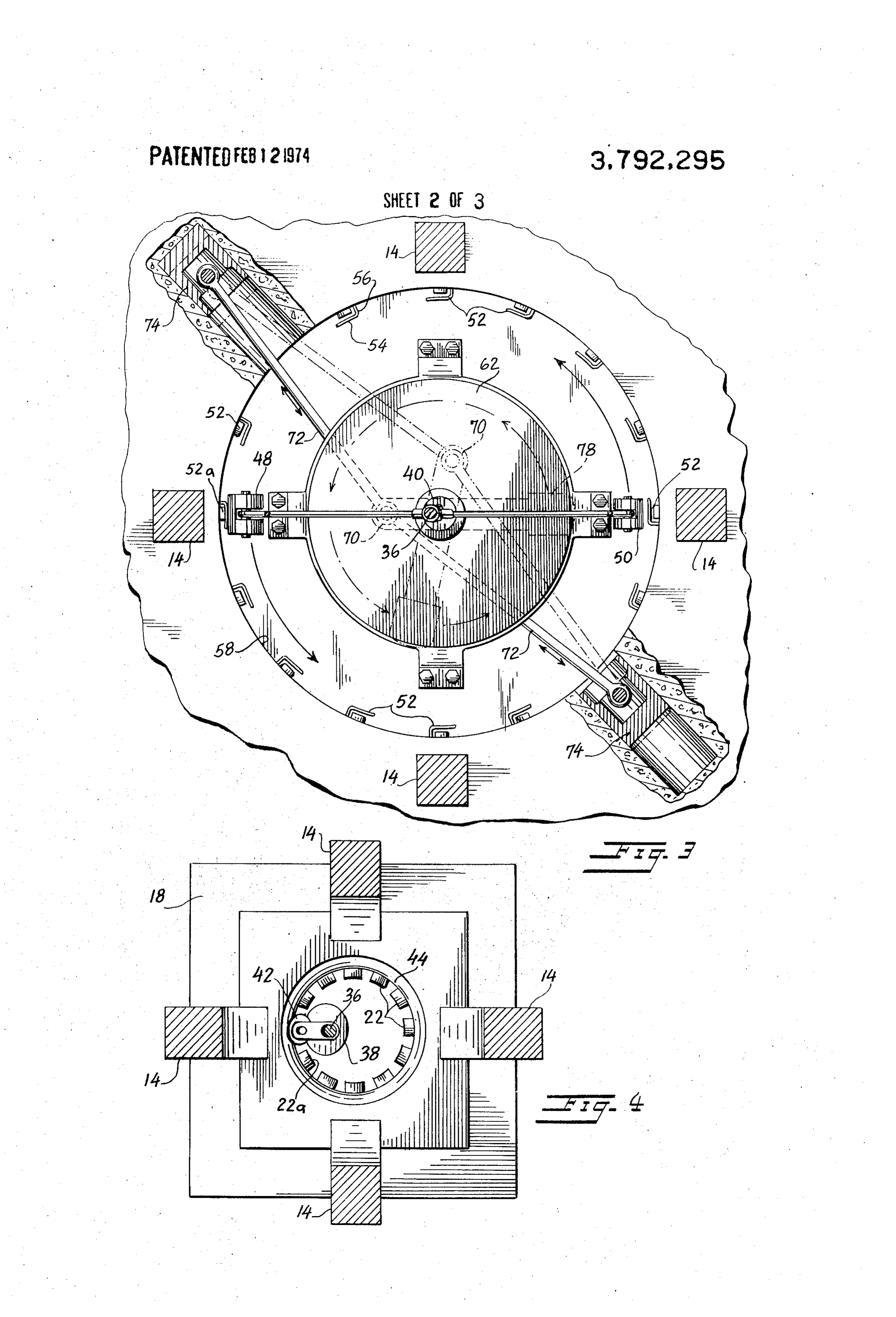
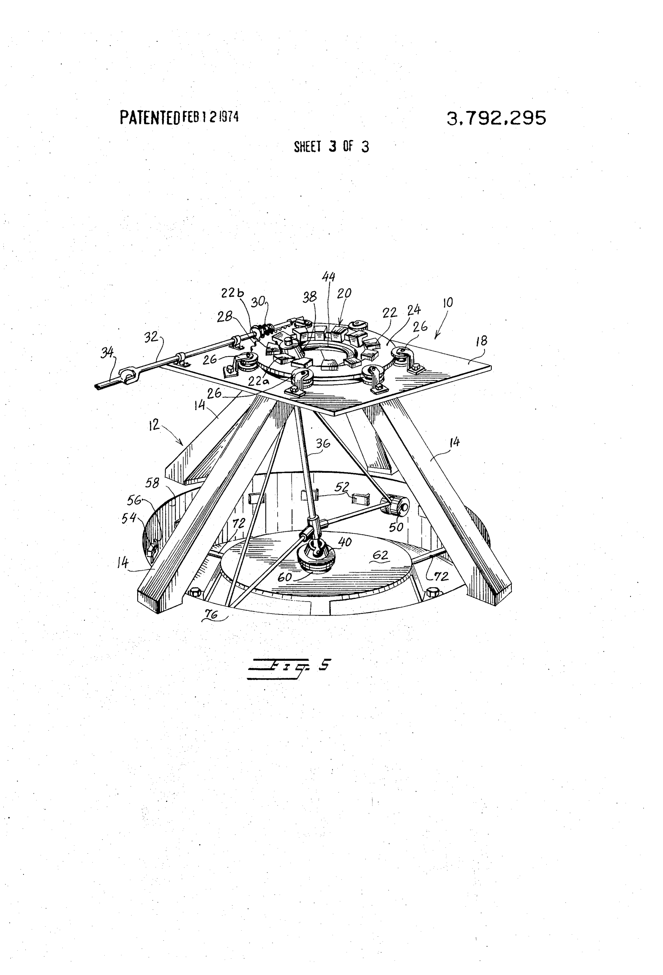
FIG. 1 is a front view, partly in section, of the kinetic should be sufficient to hold roller follower 42 in con power system of the present invention showing the stant engagement against annular track 44 as shaft 36, electromagnetic drive, the rotating weights and angled 40 together with the roller follower and the weights, rotate shaft, the crankshaft and the supporting structure. about the axis of rotation. FIG. 2 is a top view of the kinetic power system of the The operation of the invention may now be under present invention showing the segmented electromag stood. A particular electromagnetic segment 22 is ener net and the angled shaft. gized and attracts magnetic element 38 which moves FIG. 3 is a cross-sectional view taken across line 3-3 45 toward the energized segment. As magnetic element 38 of FIG. 1 showing the crankshaft pump piston linkage. approaches the energized segment 22, that segment is de-energized and the next succeeding segment in the
FIG. 4 is a cross-sectional view taken across line 4-4 direction of travel of magnetic element 38 is energized, of FIG. 1 showing the annular track and the roller fol 50 resulting in magnetic element 38 constantly being ad lower mounted on the angled shaft. vanced by the attraction of energized segments 22. FIG. 5 is a perspective view of the kinetic power sys Magnetic element 38 together with its shaft 36 are ac tem of the present invention. cordingly magnetically driven by segmented electro DESCRIPTION OF A PREFERRED EMBODIMENT magnet speed of 20 to rotate about the axis of rotation. The rotation may easily be controlled by changing
the angular distance between an energized segment 22
Referring to the drawing, the kinetic power system and magnetic element 38. Such adjustment is easily 10 of the present invention comprises a ground provided by rotation of collar 24 by means of worm 30. mounted support 12 having a plurality of reinforced The speed of rotation may be reduced by reduction in concrete or structural steel legs 14 joined at the top by 60 that angular distance, and a braking force may be ap a horizontal platform 16. In the preferred embodiment plied by locating the energized segment behind the the structure will be required to absorb great strain and magnetic element.
should be suitably strong, Mounted on platform 16 is It is the opinion of the inventor that the invention a base 18 for an annular electromagnet 20 having a plu makes use of the force of gravity to assist electromag rality of magnetic sections 22. Annular electromagnet 65 net 20 in rotating weights 48 and 50 thereby reducing 20 is horizontally disposed about a vertical axis which, the magnetic strength necessary to rotate the weights, as will be seen, is the axis of rotation of the major rotat The mechanism by which this is achieved is believed by ing elements of the invention, the inventor to be the following. When at rest weight
Page 6
48 occupies the lowest position possible by reason of Crankshaft 46 in the preferred embodiment is pro gravity. This position is in a vertical plane extending vided with a single crank 70 to which is joined opposed from magnetic element 38. As magnetic element 38 is piston rods 72 connecting two opposed piston 74, pref initially displaced a fractional amount by the action of erably located in recess in wall 58. It is obvious that ro electromagnetic segment 22, weights 48 and 50 are 5 tation of crankshaft 46 will operate opposed pistons 74 prevented by inertial forces from immediately follow and the pistons may then be used in any conventional ing. that rotational displacement. As a consequence, manner as pump pistons or the like and the output of weight 48 rises and weight 50 drops because of the dis each piston would be controlled by suitable and normal placement of magnetic element 38 with respect to connections, not shown in the drawing.
weight 48. The force of gravity now acts upon weight 10 In summary, the invention provides a machine fo 48 to bring it again to its lowest position vertically be converting electromagnetic energy into the kinetic en neath magnetic element 38 but since magnetic element ergy of rotation of weights 48 and 50 which is then 38 has been advanced weight 48 must rotate to attain transmitted through suitable crankshaft and piston rod its lowest position. Moreover, because magnetic ele connections to pump pistons 74 which provide a work ment 38 continually advances slightly ahead of weights 15 output.
48 and 50, weights 48 and 50 are in a constant state of In the preferred embodiment the kinetic power sys trying to catch up to the position of magnetic element tem 10 of the present invention would approximate 30 38, constantly trying to reach a low point. Thus, it is the feet high and 40 feet wide at its maximum width. Wall inventor's belief that rotation of the weights is accom 20 58, which could be formed as part of reinforced con plished in large part by the force of gravity. crete base 66, forms a cylindrical excavation some 6 Control of energizing and de-energizing the appropri feet deep and approximately 20 feet in diameter. ate electromagnetic segments 22 is easily provided by Weight 48 in the preferred embodiment is approxi a plurality of switches 52 mounted about the outermost mately 200 pounds and weight 50 is approximately 150 limits of the circular travel of weight 48. Each switch pounds. The speed of rotation is on The order of 180 is connected to the appropriate electromagnetic seg 25 RPM. Because of the large dynamic forces which ments 22 such that as weight 48 passes a given switch would be generated by over 350 pounds rotating at a segment 22 in advance of magnetic element 38 is en such a speed, it is desirable to construct the system ergized and the electromagnetic element 22 which is such that the weights are below ground level 76. In the adjacent magnetic element 38 is de-energized. For ex 30 unlikely event that a weight becomes disconnected and ample, consider FIGS. 2 and 3 which illustrates a given flies off tangentially to the circle of rotation, retaining position for shaft 36 and its associated elements. wall 58 and the earthen embankment behind would Weight 48 is passing switch 52a and has actuated the provide suitable security.
same. Actuation of switch 52a energizes electromag If the radial distance from the axis of rotation to the netic segment 22a and de-energizes electromagnetic 35 center of mass of each weight is 15 feet, rotation at 180 segment 22b. In the top view provided in FIGS. 2 and RPM results in the weights travelling a a velocity of 3 the direction of rotation is counterclockwise. Note, some 283 feet/second which is approximately 193 as shown in FIG. 1, that weight 50, a secondary and miles per hour. If kinetic energy E be determined by smaller weight, does not extend as great a radial dis the formula E = % mv where mass m = wig, v is veloc tance from the axis of rotation as does weight 48, which 40 ity in feet/second, w is weight in pounds and g is the is the primary and larger weight. Accordingly it is only gravitational constant of 32.174 feet/second, then, weight 48 and not weight 50 which contacts switches ergy using the dimensions and velocity stated, a kinetic en 52. of approximately 436,000 foot-pounds is attained. Each switch 52 has a cover flap 54 which is secured at one end 56 only to a wall 58, the opposite end of While the foregoing is illustrative of a preferred em cover 54 being unrestrained. The end 56 of cover 54 bodiment of the invention, it is clear that other embodi which is secured to wall 58 is that in the direction of ap ments may be had within the teachings hereof. For ex proach of weight 48 which, as seen in FIG. 3, rotates ample, the system may be used to drive rotary pumps in a counterclockwise direction. As weight 48 passes such as impeller or propeller pumps. This would avoid a switch 52 it engages cover 54 and depresses the same 50 the complication of pistons, piston rods and crankshaft. thereby closing the switch. This condition is shown at It should be noted that the complication of a crankshaft switch 52a in FIGS. 1 and 3. As weight 48 passes a includes a suitable counterweight 78.
given switch the switch returns to its normal off posi What is claimed is:
tion. 1. A machine which utilizes electromagnetic energy Switches 52 are described as being mechanically ac- 5 to generate kinetic energy, comprising: tuated. They may also be photoelectric switches, prox a rotating means;
imity switches or any other suitable switching medium. b. magnetic element means, said magnetic element means being mounted on said rotating means off
Knuckle joint support 40 turns about the axis of rota the axis of rotation; and tion on a bearing 60 which is in turn supported by a 60 c. electromagnetic means, said electromagnetic bearing support framework 62. Extending from means being situated adjacent said magnetic ele knuckle joint support 40 downwardly through bearing ment means, 60 and bearing support 62 is crankshaft 46 located at d. said electromagnetic means comprising at least its upper end by bearing 60 and intermediate its ends one segmented electromagnet, each segment of by bearing 64 secured in a ground member or rein 65 which may be individually energized to drive said forced concrete base 66. The bottom of crankshaft 46 magnetic element means, rests on a thrust bearing 68 which has suitable support e. whereby selective energization of said electromag in base 66. netic means rotationally drives said magnetic ele
Page 7
S 6 ment means and said rotating means about said axis to generate kinetic energy in accordance with claim 4, of rotation, wherein: - f. said segments of said electromagnetic means being said shaft is supported at said angle with respect to disposed in circular orientation upon a platform; said axis of rotation by a circular track supported g. said platform being rotatable about said axis of ro adjacent said electromagnetic means, said track tation, to increase or decrease the angular distance being co-axial with said axis of rotation, a roller fol from an individually energized segment to said lower mounted on said shaft engaging said track. magnetic element means and accordingly increase 6. A machine which utilizes electromagnetic energy or decrease the speed of rotation of said magnetic to generate kinetic energy, comprising:
element means, O a. rotating means, said rotating means being adapted h. said rotating means being connected to suitable to rotate about an axis of rotation and having a cen drive means. tral shaft drive element off the axis of rotation; 2. A machine which utilizes electromagnetic energy b. a weight, said weight being coupled to said rotating to generate kinetic energy in accordance with claim 1, means in continuous rotating motion initiated by wherein: 15 changes of position of said central shaft and the said rotating means comprises a shaft supported at an consequent changes of position of said weight; angle with respect to the axis of rotation. c. electromagnetic drive means, said electromagnetic 3. A machine which utilizes electromagnetic energy drive means initially displacing said drive element to generate kinetic energy in accordance with claim 2, from a first position about said axis of rotation, wherein said rotating means additionally comprises: 20 whereat said weight is at a lower level, to a second at least one weight is supported on said shaft at a dis position about said axis of rotation, whereat said tance from said axis of rotation.
4. A machine which utilizes electromagnetic energy weight is at a higher level due to initial inertial re to generate kinetic energy in accordance with claim 3, sistance of the weight to rotation about said axis of additionally comprising: 25 rotation; and a. a plurality of switches, said switches being disposed d. said continuous rotating motion being sustained along the path of rotation of said weight, said partly by said electromagnetic drive means and switches being electrically connected to said elec partly by the force of gravity which reacts to the tromagnetic means and being actuated by said higher level of said weight, weight, 30 e. whereby the force of gravity tends to lower said b. whereby said electromagnetic means is selectively weight to said low level thereby causing rotation of energized by the position of said weight with re said weight and said rotating means coupled spect to said switches. thereto.
5. A machine which utilizes electromagnetic energy
Provenance
- Collection
- Cited prior art
- Original PDF
- patentimages.storage.googleapis.com →
- Filed
- 1972-05-02
- Pages
- 7
- Method
- pdftotext (the PDF's own text layer) + pdftoppm 300dpi page scans
- Source
- Google Patents bibliographic record
- Granted
- 1974-02-12
- Inventors
- F Garbi
- Transcribed from
- patentimages.storage.googleapis.com →