patent · US4526007
Electromagnetic turbine system
2 July 1985
Page 1 — bibliographic record
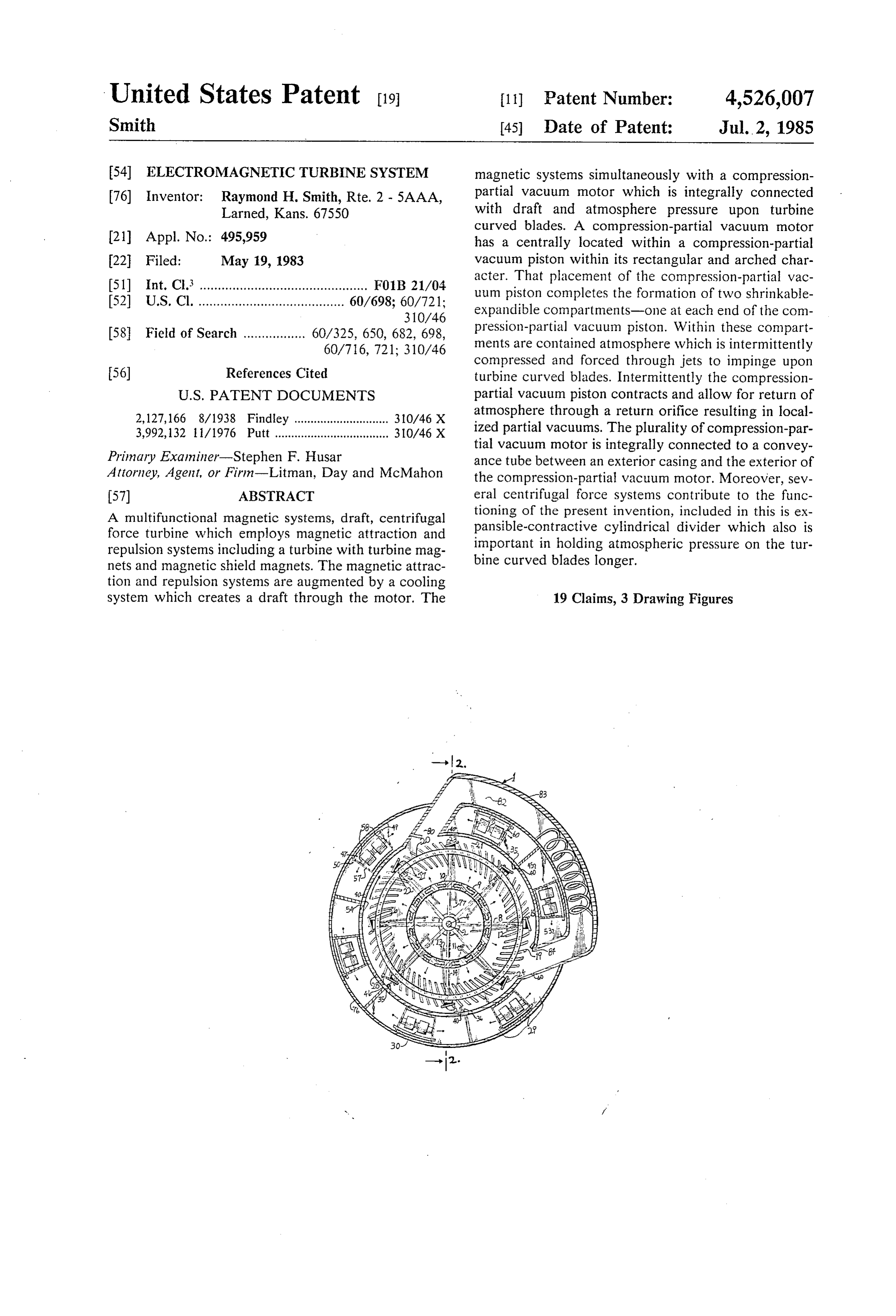
United States Patent (19) 11) Patent Number: 4,526,007 Smith (45) Date of Patent: Jul. 2, 1985 54 ELECTROMAGNETICTURBINE SYSTEM magnetic systems simultaneously with a compression 76) Inventor: Raymond H. Smith, Rte. 2 - 5AAA, partial vacuum motor which is integrally connected Larned, Kans. 67550 with draft and atmosphere pressure upon turbine curved blades. A compression-partial vacuum motor 21 Appl. No.: 495,959 has a centrally located within a compression-partial 22 Filed: May 19, 1983 vacuum piston within its rectangular and arched char (51 int. Cl. .............................................. FOB 21/04 acter. That placement of the compression-partial vac (52) U.S. Cl. ........................................ 60/698; 60/721: uum piston completes the formation of two shrinkable 310/46 expandible compartments-one at each end of the com 58. Field of Search ................. 60/325, 650, 682, 698, pression-partial vacuum piston. Within these compart 60/716, 721; 310/46 ments are contained atmosphere which is intermittently compressed and forced through jets to impinge upon 56) References Cited turbine curved blades. Intermittently the compression
2,127,166 8/1938 Findley ............................. 310/46X atmosphere through a return orifice resulting in local 3,992,132 11/1976 Putt ................................... 310/46X ized partial vacuums. The plurality of compression-par tial vacuum motor is integrally connected to a convey
Primary Examiner-Stephen F. Husar ance tube between an exterior casing and the exterior of Attorney, Agent, or Firm-Litman, Day and McMahon the compression-partial vacuum motor. Moreover, sev (57) ABSTRACT eral centrifugal force systems contribute to the func A multifunctional magnetic systems, draft, centrifugal tioning of the present invention, included in this is ex force turbine which employs magnetic attraction and pansible-contractive cylindrical divider which also is repulsion systems including a turbine with turbine mag important in holding atmospheric pressure on the tur nets and magnetic shield magnets. The magnetic attrac bine curved blades longer. tion and repulsion systems are augmented by a cooling system which creates a draft through the motor. The 19 Claims, 3 Drawing Figures
Page 2
Drawing sheet — no readable text.
Page 3
Drawing sheet — no readable text.
Page 4
Drawing sheet — no readable text.
Page 5
sion motors, and a guidance arrangement for each atmo
ELECTROMAGNETIC TURBINE SYSTEM spheric compression motor. Thus, the present invention is much more energy efficient than the two operating
BACKGROUND OF THE INVENTION separately. Moreover, the present invention, which 1. Field of the Invention enhance other systems, including draft, cooling, three The present invention relates generally to motors and centrifugal force systems, and compressing systems, to in particular to a motor utilizing a magnetic attraction perform cooperatively for central purposes. Moreover, and repulsion, centrifugal draft, and compression and generally the inputs have more than one purpose, and partial vaccum for improved performance. generally each component has more than one function A compression-partial vacuum motor comprising of a 10 in the proper functioning of the present invention. compression-partial vacuum piston disposed within the There is no known arrangement of components that central portion of the compression-partial vacuum have the particular arrangement of components nor the motor in a manner to form two opposite compartments. combined purposes, objects, and purposes conceivable A pair of magnets disposed within the compression-par from provoked cognition by this invention and Patent tial vacuum piston, each connect to diametrically oppo 15 Application.
site slidable sections of the component, and having con The development of efficient motors is particularly fronting poles of like polarity. The confronting magnets important due to the finite limitations on the world's are electromagnets. Thus, they repel one another when supply of fossil fuels.
electric current is supplied to the electromagnets, in order to extend the compression-partial vacuum piston SUMMARY OF THE INVENTION to compress atmosphere in the compartments. One of In the practice of the present invention, a motor is each of a set of electromagnets is permanently acti provided with push and pull electromagnetic systems vated. The second electromagnet of the set is intermit. and compression and localized partial vacuum systems. tently energized. By automatically discontinuing the The operation of the magnetic systems is augmented by electric current, the atmosphere in the opposite com 25 a draft which is created within the motor by a refrigera partments of the compression-partial vacuum motor tion system and heat by-products from a plurality of compresses the compression-partial vacuum piston; electromagnetic coils and jets of compressed atmo thus, resulting in a localized partial vacuum in a turbine sphere. A cooling unit functions to enhance a draft duct.
2. History of Prior Art 30 through a turbine duct. Magnetic shields are utilized in Motors utilizing magnetic repulsion and attraction conjunction operation.
with the magnets to further enhance their
Compressed atmosphere intermittently func systems are well known and a variety of such motors tion with localized partial have been developed in an attempt to maximize output ing with the other systemsvacuum and integrally cooperat physical factors and and operating efficiency. Also, the use of wind currents mechanical principals.
and drafts for imparting a rotary motion is well known 35 In addition, there is a commonly employed device on in wind mills, wind turbines and the like. Similarly, devices for compressing atmosphere are known which internal combustion engines, a coil, to enhance an elec are very efficient. tric current which is similarly employed in this inven A prior invention related hereto has been applied for tion.
by the present inventor. The previous apparatus is enti 40 Centered within a compression-partial vacuum motor tled Magnetic-Hydraulic Pump, Ser. No. 06/466,667 (atmospheric compression motor) is a compression-par and with a filing date of Feb. 15, 1983, now abandoned. tial vacuum piston containing a set of multipurpose Heretofore there has not been available a motor electromagnets to create compression and partial vacu which utilizes the principles of magnetic repulsion and ums. Within created end compartments is atmosphere. attraction and compression and localized partial vac 45 The compression-partial vacuum piston is connected uum augmented by a draft caused by a cooling system in intermittently with a turbine duct by an inlet and by an conjunction with heat, which is employed to advantage atmospheric jet directed into the turbine duct. before being discharged, from a plurality of electromag It, also, comprises the compression-partial vacuum netic coils. Reference must be made to the present in chamber and magnetic valves. The magnetic compres ventor's Magnetic Centrifugal Draft Motor, U.S. patent SO sion-partial vacuum piston has multipurpose electro application Ser. No. 448,624, filed Dec. 10, 1982. magnets with confronting poles of like polarity, The present invention is the result of fourteen years whereby the well-known repelling effect between like of thought and development on progressive apparatus, magnetic poles intermittently urges the poles apart to experimenting, and study in relation to magnetic mo furnish a compressing force on atmosphere. With the tors, and two years working with an efficient atmo 55 discontinuation of electricity to an intermittent multi spheric compression motor. A magnetic motor and an purpose electromagnet, compression springs and re atmospheric compression motor, with substantial varia turning atmosphere help urges the contraction of the tions, improvements, omissions, and additions. Some compression-partial vacuum piston.
additional components include turbine curved blades, One of the differences between the present inventor's expansible-contractive cylindrical divider, bowed at 60 invention and his previous invention, magnetic centrifu tachment (a component to lessen friction as the appara gal draft motor, is the arrangement of electromagnets. tus functions), and a conveyance tube (of the atmo In the former invention a push and pull stationary elec spheric compression motor). They are combined into tromagnet were situated to influence a plurality of tur one apparatus employing a single arrangement of mag bine magnets with opposing polarity in relation to one nets. The present invention functions in different ways 65 another. In the present invention, multipurpose electro from the inventor's previous inventions, including rear magnets, with the same polarity, attract and repel tur rangement of electromagnets, expansion and compres bine magnets in unison while also performing a second sion functioning of a plurality of atmospheric compres function of compressing atmosphere and forcing it
Page 6
through a plurality of atmospheric jets to increment the ued; furthermore, electric current intermittently acti flow of draft and directly influence a turbine. (When the vates a cooling unit. Magnetism is diminished by in electrical current is intermittently discontinued to one creased temperature; thus, there is better magnetic per of a set of multipurpose electromagnets, atmosphere is meability between cooler magnets. pulled into compression chambers and results in local Other objects and advantages of this invention will ized partial vacuum in a turbine duct in a manner and become apparent from the following description taken positioning that results in incrementing the movement in conjunction with the accompanying Drawings of the turbine.) Thus, the multipurpose electromagnets wherein are set forth by way of illustration and exam are increasing the movement of the turbine through a ple, certain embodiments of this invention. more efficient arrangement and additional purposes. 10 The Drawings constitute a part of this specification The principal objects of the present invention are: to and include exemplary embodiments of the present provide a turbine which may be used in place of con invention and illustrate various objects and features ventional electric motors, internal combustion engines, thereof.
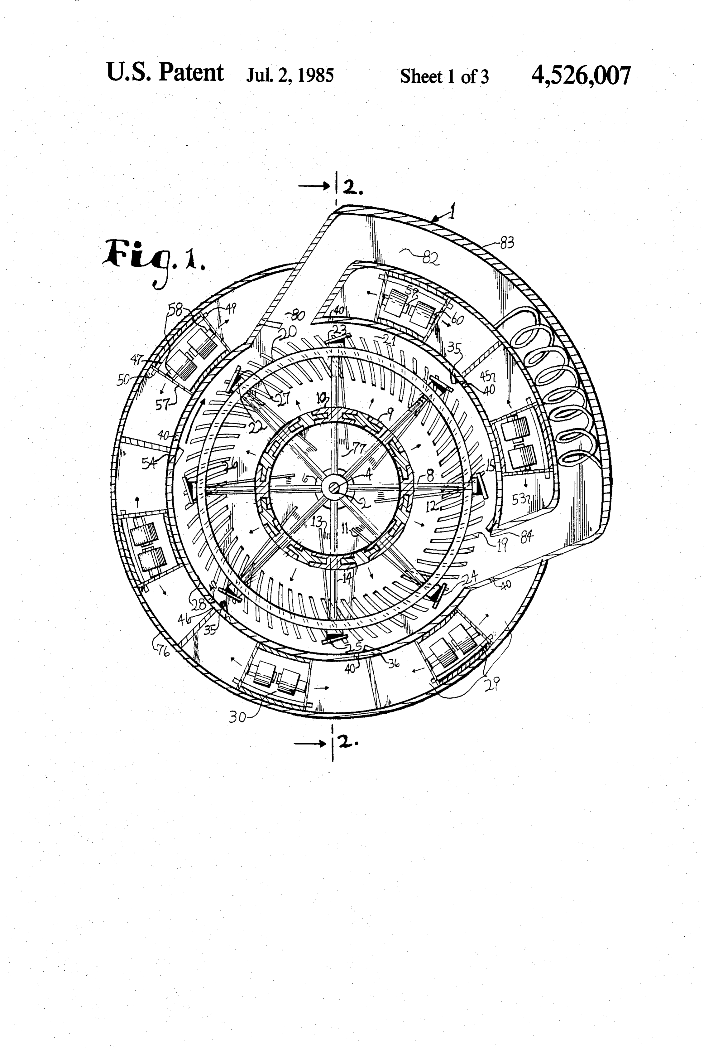
and steam engines; to provide such a motor which may be used for transporation, industry, emergency power 15 BRIEF DESCRIPTION OF THE DRAWINGS devices and the like; to provide such a turbine in con Other and further features of the present invention junction with other machinery to produce electricity; to will hereinafter more fully appear in connection with a provide such a turbine in conjunction with other equip detailed description of the drawings in which: ment to produce heat as for homes and buildings; to FIG. 1 is a cross-sectional view of a multifunctional provide such a turbine which is not reliant on fossil fuels 20 magnetic systems, draft, centrifugal force turbine em including petroleum, coal, and the like; to provide such bodying the present invention.
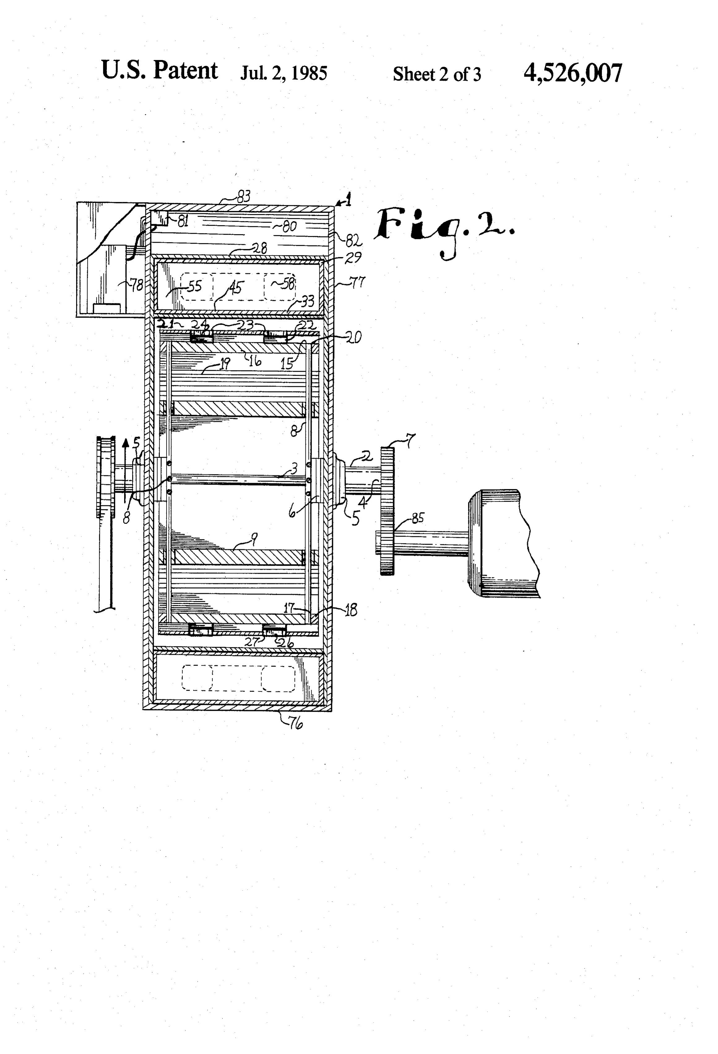
a turbine which is more versatile and less restrictive in FIG. 2 is a cross-sectional view, with parts broken utilization than conventional electric motors, internal away, of the apparatus taken generally along line 2-2 combustion engines, steam engines, atomic reactors and in FIG. 1.
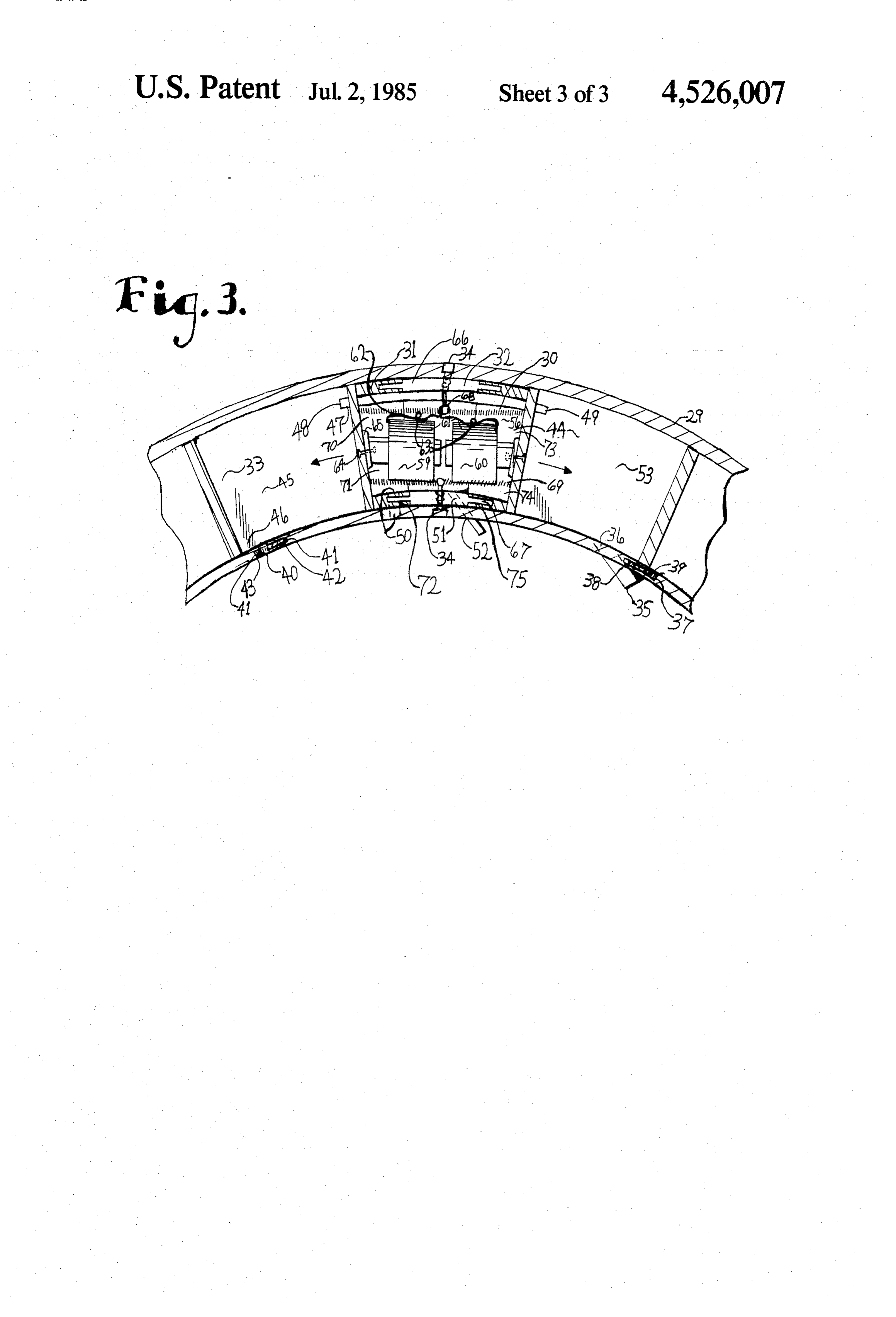
the like because of fuel requirements; to provide such a 25 FIG. 3 is an enlarged fragmented cross-sectional turbine which contributes considerably less to air and view primarily of the compression-partial vacuum water pollution than comparable internal combustion motor of the apparatus.
engines; to provide such a turbine which does not re DETALED DESCRIPTION OF THE quire extensive emissions controls; to provide such a PREFERRED EMBODIMENTS turbine which is adaptable for a wide variety of applica 30 tions with particular power, speed, and purpose require As required, detailed embodiments of the present ments; and to provide such a turbine which is economi invention are disclosed herein, however, it is to be un cal to manufacture, efficient in operation, capable of a derstood that the disclosed embodiments are merely long operating life and particularly well adapted for the exemplary of the invention which may be embodied in proposed usage thereof. 35 various forms. Therefore, specific structural and func (There are a number of ways to create more speed tional details disclosed herein are not to be interpreted and power from the apparatus. Among these are: (1) as limiting, but merely as a basis for the claims and as a improving placement and increase the number and representative basis for teaching one skilled in the art to strength of turbine magnets and multipurpose electro variously employ the present invention in virtually any magnets, (2) increasing the strength of turbine magnets, 40 appropriately detailed structure. (3) adding more rows of multipurpose electromagnets Referring to the Drawings in more detail, like refer and turbine magnets, and (4) improving the efficiency of ence numerals are applied to similar parts throughout the electrical system.) the several views. The numeral 1 generally designates a According to McGraw-Hill's Encyclopedia of Energy, multifunctional magnetic systems, draft, centrifugal 1976: Within the U.S. during the 1990s, gas and petro 45 force turbine embodying the present invention. The leum resources will begin disappearing as major compo reference numeral 76 designates an outer casing for the nents in the national energy system. Conversely, as apparatus 1. The outer casing 76 allows for the advanta noted in other sources, magnets are being improved geous housing of the various components thereof to frequently and have been particularly since the 1930s. produce the power and speed desired for a particular Moreover, as noted on page 69 of Hellman's High SO application of the apparatus 1. In particular, the outer Energy Physics. “Since the photons are not lost to the casing 76 is designed to secure and be a part of a plural particles involved, there is no energy loss which is why ity of compression-partial vacuum motors 29. a magnet does not expand energy in holding up an iron Similarly, most of the inputs contribute to the func bar, and why two charges can attract or repel each tioning of the apparatus 1 in more than one way. For other forever.' 55 instance, a plurality of permanent turbine magnets 22 An input of the present invention is permanent mag help create better permeability with coinciding multi nets, being man-made and energized power source. The purpose electromagnets 59 and 60 and contribute to plurality of permanent magnets interacting with multi total magnetic force influencing a turbine 20; the plural purpose electromagnets also improves magnetic perme ity of turbine magnets 22 contribute to centrifugal force ability. Second, an input is a refrigerant. A third input is 60 while the apparatus 1 is energized. electric current, which is regenerated by the invention Furthermore, an important aspect of this invention is and enhanced by the ignition coil. The electric current that most of the components have more than one func contributes to magnetic systems, contributes to a by tion. For example, multipurpose electromagnets 59 and product of heat from electromagnetic coils, contributes 60 are a key component in attracting and repelling the to initiate compressed atmosphere force through atmo 65 turbine 20 and for compressing atmosphere to be re spheric jets to enhance draft and impingement on the leased through atmospheric jets 35 disposed in a plural turbine. Moreover, it is important to initiating localized ity of heat atmospheric chambers 53 to influence the partial vacuums while the flow of current is discontin turbine 20 and to contribute to draft. The atmospheric
Page 7
discharge jets 35 impart atmospheric force against a The supports 8 weight considerably less than the turbine curved blades 19 and a plurality of magnetic crosspieces 16, attachments thereto and support con shields 23. Also, multipurpose electromagnets 59 and 60 nectors 18 comprises a first centrifugal force system. contribute to centrifugal force systems, and influence This relative difference in weight facilitates the centrif the proper functioning of a plurality of return orifice ugal force which enhances the operation of the appara permanent magnetic valves 42, and multipurpose elec tus 1 and provides a flywheel effect for smoother per tromagnets 59 and 60 are important to cause localized formance.
partial vacuum. Another centrifugal force system which enhances the The operation of the multifunctional magnetic sys operation of the motor comprises a constant increment tems, draft, centrifugal force turbine 1 is effected by O of systematic weight variation with respect to the magnetic Systems, a cooling System, a compression sys aligned sets of adjacent supports and the crosspieces 16. tem, a localized partial vacuum system, a draft system, It also functions to maintain momentum. There is a centrifugal force systems, a number of related physical Systematic weight increment in a progressive manner properties, and mechanical factors, including overall 5 until the maximum weight components are adjacent to design of the apparatus 1. the lightest components.
The outer casing 76 comprises a nonmagnetic mate An expansible-contractive cylindrical divider 9 con rial and includes components which are suitably joined sists of a movable membrane within a sheath 10. Thus, in a detachable manner so as to allow access to compo it allows expansion while the apparatus 1 is activated, nents positioned in the interior of the outer casing. and then contracts to its former position when the appa A shaft 2 is centrally located within the apparatus 1 20 ratus 1 stops. The expansible-contractive cylindrical and includes a plurality of supports 8 which radiate divider 9 moves farther outwardly from the shaft 2 outwardly from the shaft in spaced positions whereby a while the apparatus is in incessant motion and thus spoke-like configuration is formed as shown in FIG. 1. comprising a third centrifugal force system. The supports 8 extend radially outwardly from the shaft 25 There is a component to lessen friction between ex 2 in equally spaced relation with respect to each other. pansible-contractive cylindrical divider 9 and the sup The supports 8 terminate at respective far ends 15 equi ports 8. Each support 8 has a bowed attachment 11 distance from the shaft 2. There is a different number of which is affixed and extend from an outermost end of supports 8 to the number of compression-partial vac the support 12 and to a bowed attachment spring 13 uum motors 29 to prevent potential magnetic drag oc nearer the shaft 2 on forward side to the direction of the curing at simultaneous intervals. turbine's movement 14. With the deactivation of the The far ends of the supports 15 have crosspieces 16 apparatus 1, the bowed attachment spring 13 press in connected thereto and longitudinally aligned with the wardly toward the support 8.
shaft 2. The shaft and the supports 8 comprise portions Fixedly mounted on the crosspieces 16 are permanent of the turbine 20, The shaft 2 extends through the center 35 turbine magnets 22 which are intermittently brought of the turbine 20 coaxially therewith. into proximity to multipurpose electromagnets 59 and A plurality of support connectors 18 extend in a 60 by rotation of the turbine 20. The turbine magnets 22 transverse manner relative to the shaft 2 and in a circu are bar magnets and are spaced and alternated in orien lar manner with respect to the respective supports 8 tation on each of the crosspieces 16 in a systematic which are positioned on ends 17 of respective cross 40 manner so that in relation to the movement of the tur pieces 16. The plurality of turbine curved blades 19 are bine 20, the front pole of the turbine magnets 22 are of appended from one support connector 18 to another the opposite magnetic charge of respective multipur support connector in a parallel manner to the shaft 2 pose electromagnets 59 and 60. The poles of the turbine and are effected favorably by the draft. The plurality of magnets 22 determine whether pulled or pushed at a turbine curved blades 19 are shown in FIG. I. The 45 given instance as a result of having the same polarity turbine 20 is aerodynamically designed in such a way as and opposite polarity as multipurpose electromagnets to minimize atmospheric resistance to rotation. The 59 and 60, turbine 20 is mounted within a turbine duct 21 in an One of a set of multipurpose electromagnets 58 is unrestrained manner. intermittently energized 60 and the second multipur The shaft 2 includes a central portion 3 with a lesser 50 pose electromagnet 59 is constantly energized. They are diameter than shaft end portions 4. Bearing units 5 re supplied with a source of alternating current (not ceive the end portions of the shaft 4. The shaft 2 extends shown) as long as the apparatus 1 is activated. The in an unrestrained manner through washers 6, bearings apparatus 1 is provided with a commutator for intermit units 5 and beyond end outer casings 77 which are posi tently changing the direction of current (also not tioned perpendicularly to the shaft. The washers 6 are 55 shown).
positioned between each bearing unit 5 and respective Associated with each turbine magnet 22 is the respec supports 8 about the shaft 2 to maintain appropriate tive magnetic shield 23 comprising a nonmagnetic mate spacing therebetween to allow for better movement of rial 27. A magnetic shield magnet 24 is mounted on each the shaft, magnetic shield 23. One of the main purposes of the A shaft cog 7 is attached to an end portion of the shaft 60 magnetic shield magnets 24 is to limit drag of the tur 2. The shaft cog 7 is adapted to mesh with an extrinsic bine magnets 22 in relation to the multipurpose electro component 85 which is to be driven by the multifunc magnets 59 and 60 with as little adverse effect as possi tional magnetic systems, draft, compression force tur ble. The magnetic shield magnet 24 has an inner pole, bine 1. As an alternative to the shaft cog 7, a direct drive which is opposite to the turbine magnet 22, that is to connection between the shaft 2 and the extrinsic compo 65 help reduce undesirable magnetism between the turbine nent 85 may be utilized. The extrinsic component 85 magnet 22 and the multipurpose electromagnets 59 and may comprise any of a variety of types of machinery 60. Thus, the magnetic shield magnets 24 must be rela and the like to be driven by the apparatus 1. tively weak.
Page 8
The magnetic shield magnets 24 are slanted, prefera Outer poles 25 of the magnetic shield magnets 24 are bly at an angle of less than 45 degrees in relation to the not covered by any material. Similarly, inner poles 26 of turbine magnets 22. The poles of the magnetic shield the magnetic shield magnets 24 are spaced from the magnets 24 are thus oriented so that they will be influ nonmagnetic material 27 that they are affixed to. enced by the poles of the multipurpose electromagnets The strengths of the cooperating magnets 22, 24, 59, 59 and 60 having the same polarity while preventing and 60 and the relative distances therebetween are im stronger permanent turbine magnets 22 from periodi portant as a result of adversely affecting upon one an cally reacting adversely with electromagnets 59 and 60. other, especially reversing polarity of successively Moreover, the angular orientation of the magnetic weak magnets which are incorrectly placed in a cooper shield magnets 24 functions to limit periodical interfer O ative manner with very strong magnets. The proper ence of the turbine magnets 22 and the multipurpose placement of the magnetic shield magnets 24 and their electromagnets 59 and 60. respective distances from the permanent turbine mag The magnetic shield magnets 24 are affixed to the nets 22 are as shown in FIG. 1. However, they should nonmagnetic material 27 of the magnetic shield 23 in a be in spaced relation. Preferably, the magnetic shield systematic angle with respect to the turbine magnets 22 15 magnets 24 are substantially weaker than either of the in the turbine paths thereof. The angulation of the mag multipurpose electromagnets 59 and 60. netic shield magnets 24 is determined primarily by the Within an interior of a compression-partial vacuum strengths of the multipurpose electromagnets 59 and 60, motor 44 are two mobile pins 71 and 74 which are por the turbine magnets 22 and the respective distance be 20 tions of compression-partial vacuum piston. The pans tween various magnets 22, 24, 59, and 60. Another fac 71 and 74 contour with the outer casing of the multi tor in determining the appropriate angle of orientation functional magnetic systems, draft, centrifugal force for the magnetic shield magnets 24 relates to the diame turbine 1. Also, the mobile pans 71 and 74 consisting of ter of the turbine 20. The magnetic shield 23 rotates a segment one 70 and a segment two 73 which consti with the turbine 20 in a position beyond the pheriphery 25 tutes a planar portion 57 of each segment and nonfer of permanent turbine magnets 22. rous side walls 31 and are the interior of a compression The polarity of the magnetic shield magnets 24 is the partial vacuum piston 56. A piston 30, which includes same as that of the poles of the multipurpose electro mobile arched nonferrous pans 71 and 74 and multipur magnets 59 and 60 which influence them. Thus, the pose electromagnets 59 and 60, acts to compress atmo permanent turbine magnets 22 are much less adversely 30 sphere which is present at each end of the compression affected by the multipurpose electromagnets 59 and 60 partial vacuum piston 30 in atmospheric chambers 45 which are periodically in a position beyond the periph and 53.
eral path of the turbine magnets 22. The compression-partial vacuum motor 29 is within Preferably, the magnetic shield magnets 24 are an inner casing 28 and the outer casing 76. The com weaker than the multipurpose electromagnets 59 and 60 35 pression-partial vacuum motor 29 is constructed in a and weaker than the turbine magnets 22. The magnetic curved manner to conform to the outer casing 76. The shield magnets 24 are substantially weaker than the inner casing conforms to the outer casing 76 and is permanent turbine magnets 22 in their respective mag appended to a portion of the compression-partial vac netic interaction with the multipurpose electromagnets uum motor 29 as shown in FIG. 2. The plurality of 59 and 60. 40 compression-partial vacuum motors 29 are appended to As shown in FIG. 1, the magnetic shield magnets 24 one another in a consecutive manner.
are angulated to allow the multipurpose electromagnets The compression-partial vacuum piston 30 has non 59 and 60 to influence the turbine magnets 22 in a direc ferrous side walls 31 with internal slots 72 and 75 which tion more toward the proper direction of rotation of the conform to the shape of the sides. An immobile wall turbine 20. The angulation of the magnetic shield mag 45 section 66 is primarily centered in relation to the various nets 24 is preferable to affixing them parallel with the lengths of the compression-partial vacuum piston 30, permanent turbine magnets 22 which would result in The immobile wall section 66 is attached to the correct the multipurpose electromagnets 59 and 60 exerting casing 76, 28, and to the end outer casing 77 and has forces directed radially toward the center of the turbine guides 67 within slots 72 and 75 in the nonferrous side 20, thus, slowing the motion of the turbine with the 50 walls 31 of the mobile heel arched nonferrous pan 71 multifunctional magnetic systems, draft, centrifugal and the mobile head arched nonferrous pan 74 to allow force turbine 1 in operation. expansion and contraction as shown in FIG. 3. The As noted the multipurpose electromagnets 59 and 60 internal slots 72 and 75 in the mobile heel nonferrous exert force upon the magnetic shield magnets 24 in a pan 71 and in the mobile head nonferrous pan 74 for the direction that is more complimentary to the rotary mo 55 induction of the immobile wall section of the compres tion of the turbine 20 and thus help to propel it, also, it sion-partial vacuum piston 74 to allow proper guidance contributes to helping initial starting in cooperation during expansion and compression of compressive-par with the multipurpose electromagnets 59 and 60 and tial vacuum piston. The central portion of the compres draft systems. However, before the magnetic shield sion-partial vacuum piston 32 is also the center of the magnets 24 are in their respective beneficial positions as 60 immobile wall section 66 and is attached, as by bolts 34, heretofore described, a certain amount of magnetic to the contiguous casings.
interference between the magnetic shield magnets 24 Within the interior of the compression-partial vac and the multipurpose electromagnets 59 and 60 occurs. uum piston 30 and attached to the immobile wall section This magnetic interference is considerably less than it 66 is attached an extended ring 68. As shown in FIG. 2, would be if the magnetic shield magnets 24 were re 65 there is a compression spring 69 attached to each ex placed by a diamagnetic material with all of the other tended ring 68 for each planar portion 57 of the com variables such as relative placement and distance be pression-partial vacuum piston 30; thus, allowing a tween the components being the same. more correct angle of force of the compression springs
Page 9
69 to help with contraction during the intermittent through the inner casing 28 and through the guide por operation. tion of immobile wall section 67 and there is a smaller The multipurpose electromagnets 59 and 60 of each adjoining orifice in immobile section 51 and immobile pair are energized by a supply of electric current, to its section orifice nozzle 52 which impinges heated atmo coil 6. One of the multipurpose electromagnets 60 is 5 sphere upon the turbine curved blades 19 which is sup intermittently energized and one of the multipurpose plementary to the other forces of the apparatus 1. electromagnets 59 is continuously activated by a source As shown in FIG. 1, a return orifice 40 is disposed at of alternating electrical current (not shown). Each set of the hindmost portion 46 of each heel atmospheric cham multipurpose electromagnets 58 are arranged with their ber 45 to allow the entrance of atmosphere to result in axis linear and in linear alignment of the multipurpose 10 localized partial vacuums to influence the turbine 20 electromagnets 59 and 60 being fixed to the farthest and draft in the correct manner and to ready the com planar portion of the pans 57, as by rivets 64. The elec pression-partial vacuum motor 29 for a compression tromagnet coil 61 of the multipurpose electromagnets stroke to force atmosphere through atmospheric dis 59 is so wound that the confronting poles of the multi charge jets 35 located at the forefront of the head atmo purpose electromagnet 60 are of like polarity, that is, 15 spheric chamber 54.
both north poles or both south poles. Thus, when cur Within a plurality of return orifice slots 41 in the rent is supplied to the intermittently activated multipur non-ferrous side wall 31 are a plurality of a return ori pose electromagnets 60, they repel each other, and fice permanent hence supply a force tending to extend in opposite di heel atmosphericmagnetic chamber valve 42 magnetized in the 45 in relation to the hindmost rections the compression-partial vacuum piston 30. 20 portion in relation to the progress Thus, compressing the atmosphere within a compres movement. In a related position in theof the turbine 20 sion-partial vacuum chamber 33 within each end of the chamber 53 is a jet magnetic slot 37 in theatmospheric head compression-partial vacuum motor 29. Thus, being effi side wall 31 for jet orifice permanent magnetnonferrous valves 38 cient in employing the compressive energy of the appa to open and close the valve to the atmospheric dis
Displacement of atmosphere by the compression-par charge jets 35 intermittently. tial vacuum piston 30 partially results from the size of a tialUpon the approach of the magnetic compression-par vacuum piston 30, the movable permanent magnet compression-partial vacuum piston's planar surface 55.
Current is supplied by an electric cable 62, and the valves 38 and 42 are repelled further outwardly from necessary leads to the multipurpose electromagnets 59 30 the compression-partial vacuum piston; thus, intermit and 60 are contained in the electric cable 62 which tently opening a head atmospheric chamber discharge enters body member in its immobile wall section 66 of jet fice orifice 36 and intermittently opening the return ori 40. This arrangement allows the functioning of the the compression-partial vacuum piston 30. Cable leads are provided with sufficient slack, as indicated at 63, to valves 38 and 42 regardless of the positioning of the permit extension of the compression-partial vacuum 35 apparatus 1. A return orifice permanent magnet valve piston 30. return springs 43 and a jet orifice permanent magnet In use, the compression-partial vacuum piston 30 is valve return spring 39 return the return orifice perma supported within the central portion of the compres nent magnetic valve 42 and the jet orifice permanent sion-partial vacuum motor 29, and the outermost face of magnet valve 38, respectively, into positions in relation the compression-partial vacuum piston 30 is positioned 40 to nonexpansion of the compression-partial vacuum to influence the atmosphere in opposite atmospheric piston 30.
chambers 33. The purpose of dual atmospheric cham Upon the contraction of the compression-partial vac bers 33 is to take advantage of Newton's law of opposite uum piston 30, the jet orifice permanent magnet valve and equal reactions. Thus, employing both the equal 38 and return orifice permanent magnet valve 42 con and opposite force resulting from the intermittent ex 45 tract; thus, the former valve 38 covers the jet orifice 36 pansion functioning of compression-partial vacuum and the latter valve 42 opens the return orifice 40. (An piston 30. Therefore, representing an extremely effi alternating embodiment is to employ a different type of cient manner to perform appropriately. valve, as pressure valves which would open in the de The magnetic shield magnets 24 and turbine magnets sired manner to reduce pressure.)
22 slightly distort this law in relation to the compres 50 Upon discontinuation of electrical current to one of sion-partial vacuum piston 30, as while the turbine mag the multipurpose electromagnets 59 of each set 58, the nets 22 are being attracted by multipurpose electromag compression-partial vacuum piston 30 is compressed by nets 59 and 60. While that is happening the multipur the pressure of the remaining atmosphere. Moreover, pose electromagnets 59 and 60 are toward a hindmost compression springs 69 urge contraction of the mobile portion 46 of the heel atmospheric chamber 45 than 55 heel arched nonferrous pan 71 and the mobile head they otherwise would be. arched nonferrous pan 74 of the compression-partial A conveyance tube 47 connects the head atmospheric vacuum piston 30 intermittently upon the discontinua chamber 53 and the heel atmospheric chamber 45 of one tion of the electric current to one of the set of two compression-partial vacuum motor 29. The conveyance multipurpose electromagnet 60. This action creates a tube 47 has an inlet 48 from the heel atmospheric cham 60 degree of suction and allows more atmosphere more ber 45 and an outlet 49 to the head atmospheric cham rapidly from the return orifice 40; thus, readying the ber 53. The heel atmospheric chamber 45 and head compression-partial vacuum piston 30 to again be ex atmospheric chamber 53 cooperate to force atmosphere panded.
through the atmospheric discharge jet 35 which directs The efficiency can be adjusted by the multipurpose a compressed jet of atmosphere to influence rotary 65 electromagnetic coils 61 employed as well as the size of motion and draft in the correct manner. compression-partial vacuum piston 30 and number of There is an inlet into the interior piston 50 from the raps of the multipurpose electromagnets 59 and 60 and turbine duct 21 to help cool electromagnets. The inlet is other similar factors.
Page 10
The compression-partial vacuum motor 29 can be a position to influence draft in a cooperative manner designed through conventional knowledge of whether with the movement of the turbine 20.
to perform in relation to a greater distance or a shorter An uplifting draft on the turbine 20 is created as a distance with greater force. result of a number of factors, including the cooling In operation, a compression and heat-induced draft unit's operation, design of the turbine 20, heat from the through the multifunctional magnetic systems, draft, multipurpose electromagnets 59 and 60, and magnetic centrifugal force turbine 1 assists in overcoming mag compression-partial vacuum motors 29; (also, cooler netic interference. Furthermore, during motion of the magnets function better than hot ones.) turbine 20, the centrifugal forces developed thereby The cooling unit 78 is provided with a cooling unit tend to overcome any adverse effects of magnetism. 10 thermostat 81 to activate it at a predetermined tempera Thus, the two major magnetic systems of the appara ture. The cooling unit 78 and the cooling unit channel tus 1 are attraction and repulsion of the turbine magnets 82 are designed to cool the multifunctional magnetic 22 by the multipurpose electromagnets 59 and 60. The systems, draft, centrifugal force turbine's internal atmo multipurpose electromagnets 59 and 60 are positioned sphere and components, especially the multipurpose so as to intermittently attract and intermittently repulse 15 electromagnetic coils 61 and to contribute to the draft the turbine magnets 22 which are constantly activated. which facilitates rotation of the turbine 20. It is antici The constantly activated turbine magnets 22 are inter pated that a converter may be employed in connection mittently influenced by the multipurpose electromag with the cooling unit 78.
The turbine magnets 22 may assume various shapes nets 59 and 60 while moving into the direct line of influ 20 including elCe. rectangular and the turbine magnets may be As shown in FIG. 2, U-shaped multipurpose electro electromagnets. As an additional variation, the shape of magnets 59 and 60 each influence two turbine magnets the multipurpose electromagnets 59 and 60 within the 22 on a respective crosspiece 16. The multipurpose apparatus 1 can vary in a systematic manner and there electromagnets 59 and 60 also repulse the poles of tur can be various types of multipurpose electromagnets in bine magnets 22 of the same magnetism when posi 25 different models, including E-shaped and bar shaped. The apparatus 1 employs a storage battery (not tioned adjacent in a passed position.
The multipurpose electromagnets 59 and 60 in a row shown), a coil (not shown), a generating means (not shown), a voltage regulating means (not shown), and in the apparatus 1 have the same angulation with re other spect to the inner casing 28 and to the turbine magnet 22 30 internalcomponents (not shown) employed with a typical at respective predetermined positions on the course of an additional externalengine.
combustion source
The apparatus 1 may have of electricity, especially the turbine magnets. The multipurpose electromagnets when the work load is very heavy 59 and 60 are secured by respective appendage compo 1 revolves excessively slowly. and/or the apparatus nents 65.
Magnetism is diminished by increased temperature. 35 magnetic In another variation, the turbine magnets 22 and the Thus, greater magnetic permeability within the multi plurality ofshield magnets 24 can be disposed within a functional magnetic systems, draft, centrifugal force from friction. casings to lessen heat effect resulting small turbine 1 is accomplished by maintaining a lower tem In yet another variation (not shown), a disc brake perature therein. may be provided mounted to a stationary component of In order to cool the interior of the apparatus 1, a 40 the apparatus 1. The disc of the disc brake rotates with cooling unit 78 is provided with a cooling unit coil 79. the
In operation, the cooling unit 78 helps create a draft stopsshaft the 2 while the shaft is in unhampered motion and rotation thereof while a selector of functions within the apparatus 1 which tends to cool the multipur releases and activates the disc brake. pose electromagnetic coils 61 and, furthermore, facili An alternative embodiment is to employ a direct tates rotation of the turbine 20 by the draft atmospheric 45 source of alternating electrical current; thus, making a movement which increases the rate of revolutions of the commutator unnecessary.
turbine. The augmented internal atmospheric draft is Another alternative embodiment is to employ super assisted by the head atmospheric discharge jet 35, im cooled multipurpose electromagnets 59 and 60 with the mobile section orifice nozzle 52, and turbine curved necessary alternations.
blades 19. The cooling unit 78 operates on, for example, 50 It is to be understood that while certain forms of the the same source of alternating electric current as the present invention have been illustrated and described multipurpose electromagnets 59 and 60. herein, it is not to be limited to the specific forms or A warm atmospheric inlet orifice 80 for internal at arrangement of parts described and shown. mospheric gas is shown in FIG. 1 near the top of the The following listing of components, etc. is an aid in multifunctional magnetic systems, draft, centrifugal 55 correlating terms in the claims to exemplary drawings, turbine 1 and provides an entrance to a cooling unit the terms and reference numerals are: channel 82. The cooling unit channel 82 extends from 1 multifunctional magnetic systems, draft, centrifugal the warm atmospheric inlet orifice 80 toward the bot force turbine tom of the apparatus 1 as shown in FIG. and termi 2 shaft nates at a cooler atmospheric outlet orifice 84. The 60 3 central reduced portion of shaft cooler atmospheric outlet orifice 84 is situated to allow 4 shaft end portions cooler atmosphere to impinge against the turbine 5 bearing unit curved blades 19. The cooling unit channel 82 is situ 6 washer ated in a position to influence draft in a cooperative 7 shaft cog manner with the movement of the turbine 20 while 65 8 support employing characteristics of warm and cool atmo 9 expansible-contractive cylindrical divider spheres. The cooling unit channel 82, including the 10 sheath of expansible-contractive cylindrical divider outermost cooling unit channel casing 83, is situated in 11 bowed attachment
Page 11
12 bowed attachment to the outermost end of support 74 mobile head arched nonferrous pan 13 bowed attachment spring 75 internal slot of head nonferrous pan 14 foreward side to the direction of turbine's movement 76 outer casing 15 far end of support 77 end outer casing 16 crosspiece 78 cooling unit 17 end of crosspiece 79 cooling unit coil 18 support connector 80 warm atmospheric inlet orifice 19 turbine curved blades 81 cooling unit thermostat 20 turbine 82 cooling unit channel 2 turbine duct 10 83 outermost cooling unit channel casing 22 turbine magnet 84 cooler atmospheric outlet orifice 23 magnetic shield 85 extrinsic component 24 magnetic shield magnet I claim:
25 outer poles of magnetic shield magnet 1. An electromagnetic turbine system, which com 26 inner poles of magnetic shield magnet 5 prises:
27 nonmagnetic material (a) an inner casing;
28 inner casing (b) a turbine including turbine blades rotatably 29 compression-partial vacuum motor mounted in said inner casing; 30 compression-partial vacuum piston (c) a turbine magnet mounted on said turbine; 31 nonferrous side wall of compression-partial vacuum 20 (d) an outer casing at least partly surrounding said piston inner casing;
32 central portion of compression-partial vacuum piston (e) air pump means mounted between said inner and 33 compression-partial vacuum chamber outer casings and including: 34 bolt (1) a pair of electromagnets positioned in opposed 35 atmospheric discharge jet 25 relation to each other; and 36 head atmospheric chamber discharge jet orifice (2) a piston slidably positioned between said inner 37 jet magnetic slot and outer casings and connected to at least one 38 jet orifice permanent magnet valve of said electromagnets; 39 jet orifice permanent magnet valve return spring (f) discharge and return orifices in said inner casing 40 return orifice 30 for communicating air from said air pump means to 41 return orifice slot said turbine blades; and 42 return orifice permanent magnet valve (g) means for selectively energizing at least one of 43 return orifice permanent magnet valve return spring said electromagnets.
44 interior of compression-partial vacuum motor 2. The apparatus according to claim 1, which in 45 heel atmospheric chamber of compression-partial 35 cludes:
Vacuu Otor (a) a cooling unit mounted on said outer casing and 46 hindmost portion of heel chamber having:
47 conveyance tube (1) a cooling unit channel with a warm air inlet 48 inlet of conveyance tube orifice and a cool air outlet orifice each commu 49 outlet of conveyance tube 40 nicating with said inner casing; 50 inlet into interior of compression-partial vacuum (2) cooling unit located within said cooling unit piston through inner casing and guide channel; and 51 orifice in the immobile section (3) refrigeration means for passing a fluid through 52 immobile section orifice nozzle said cooling unit coils at a temperature lower 53 head atmospheric chamber of compression-partial 45 than the ambient air temperature within said vacuum motor) System; and 54 forefront of head atmospheric chamber (b) said cooling unit being adapted to create a draft 55 compression-partial vacuum piston's planar surface from said warm air inlet orifice, through said cool 56 interior of compression-partial vacuum piston ing unit coils and from said cool air outlet orifice 57 planar portion of interior of compression-partial 50 into said inner casing whereby said draft encoun vacuum piston ters said turbine blades and facilitates the rotation 58 set of multipurpose electromagnet of said turbine.
59 constantly activated multipurpose electromagnet 3. The system according to claim 2, which includes: 60 intermittently activated multipurpose electromagnet (a) a thermostat located within said cooling unit chan 61 multipurpose electromagnetic coil 55 nel for activating said cooling unit at a predeter 62 electric cable mined temperature.
63 slack electric cable 4. The system according to claim 1, which includes: 64 rivet (a) a plurality of said permanent turbine magnets 65 appendage component (securing multipurpose elec mounted on a circumference of said turbine. tromagnets) 60 5. The system according to claim 4, which includes: 66 immobile wall section (a) a plurality of magnetic shields each comprising a 67 guide portion of immobile wall section nonmagnetic material and mounted on a respective 68 extended ring permanent turbine magnet.
69 compression spring 6. The system according to claim 5, which includes: 70 segment one 65 (a) a plurality of permanent magnetic shield magnets 71 mobile heel arched nonferrous pan each mounted on a respective magnetic shield and 72 internal slot of heel nonferrous pan angularly disposed with respect to a tangent to a 73 segment two path of revolution of said magnetic shield magnets.
Page 12
7. The system according to claim 6 wherein: (a) attachment means for said cylindrical divider (a) said turbine magnets are aligned with a tangent to including a spring adapted to facilitate the expan a path of rotation thereof; sion and contraction thereof. (b) each said magnetic shield magnet being angled 19. An electromagnetic turbine system, which em with respect to an associated turbine magnet at an is prises:
angle of 45 degrees or less, a leading edge of said (a) an inner casing;
magnetic shield magnet being located further from (b) a turbine rotatably mounted in said inner casing the turbine rotational axis than a trailing edge and including:
thereof. (1) a shaft coaxial with an axis of rotation of said 8. The system according to claim 1, which includes: O turbine;
(a) a plurality of said air pump means mounted in (2) a cylindrical divider connected to said shaft and radially spaced relation between said inner and adapted to expand radially outwardly by centrif outer casings. ugal force associated with the rotation of said 9. The system according to claim 1 wherein: turbine;
(a) said piston includes a pair of piston segments each 15 (3) a plurality of turbine blades mounted on said attached to a respective electromagnet and slidably rotor and angled with respect to a direction of disposed between said inner and outer casings. rotation of said turbine; 10. The system according to claim 9, which includes: (4) a plurality of permanent turbine magnets mounted in radially spaced relation on said tur (a) a return chamber between said inner and outer 20 bine in proximity to said blades; casings and adjacent to one of said segments, said (5) a plurality of nonmagnetic magnet shields each return chamber being selectively open at said re mounted on a respective turbine magnet; and turn orifice; and (6) a plurality of magnetic shield magnets each (b) a discharge chamber between said inner and outer mounted on a respective magnet shield; casings adjacent to said other segment, said dis- 25 (c) an outer casing at least partly surrounding said charge chamber being selectively open at said dis inner casing in radially-outwardly spaced relation charge orifice. therefrom;
11. The system according to claim 9, which includes: (d) a plurality of air pump means positioned in radi (a) said segments being interconnected by return ally spaced relation between said inner and outer springs adapted for biasing said segments toward 30 casings, each said air pump means including: each other when said electromagnets are deener (1) a piston including a pair of piston segments gized. slidably disposed between said inner and outer 12. The system according to claim 9, which includes: casings;
(a) an air conveyance tube extending through said (2) return and discharge chambers enclosed be segments and communicating said return and dis-35 tween said inner and outer casings and each charge chambers. being associated with a respective piston seg 13. The system according to claim 1, which includes: ment;
(a) a magnetic inlet valve selectively closing said inlet (3) a pair of electromagnets each mounted on a orifice; and respective piston segment in opposed relation; (b) a magnetic return valve selectively, closing said 40 (f) a plurality of discharge valves each associated return orifice. with a respective discharge chamber and including 14. The system according to claim 13, which in a discharge orifice through said inner casing and a cludes: discharge magnet member adapted for selectively (a) said return and discharge valves each having a 45 closing said discharge orifice; respective magnet member. (g) a plurality of return valves each associated with a 15. The system according to claim 14, wherein: respective return chamber and including a return (a) said magnet members are slidably received in orifice and a return valve magnet adapted for selec respective return and discharge valve slots in said tively closing return orifice; inner casing, said slots communicating with return 50 (h) a cooling unit mounted on said outer casing and and discharge orifices respectively. including:
16. The system according to claim 1, which includes: (1) a cooling unit channel with a warm air inlet orifice and a cool air outlet orifice each commu (a) an air discharge jet communicating with said dis- . nicating with said inner casing; charge orifice and angled in a direction of rotation (2) cooling coils located within said cooling unit
channels; and 17. The system according to claim 1, which includes: (3) refrigeration means for passing a fluid through (a) a cylindrical divider coaxially mounted on said Said cooling unit coils at a temperature lower turbine and adapted to expand radially outwardly than the ambient air temperature within said by centrifugal force associated with the rotation of system; and said turbine. 60 (i) means for selectively energizing said electromag 18. The system according to claim 17, which in netS.
cludes: ck k k k sk
Provenance
- Collection
- Cited prior art
- Original PDF
- patentimages.storage.googleapis.com →
- Filed
- 1983-05-19
- Pages
- 12
- Method
- pdftotext (the PDF's own text layer) + pdftoppm 300dpi page scans
- Source
- Google Patents bibliographic record
- Granted
- 1985-07-02
- Inventors
- Raymond H. Smith
- Transcribed from
- patentimages.storage.googleapis.com →