patent · US4167684
Magnetic torque multiplier
11 September 1979
Page 1 — bibliographic record
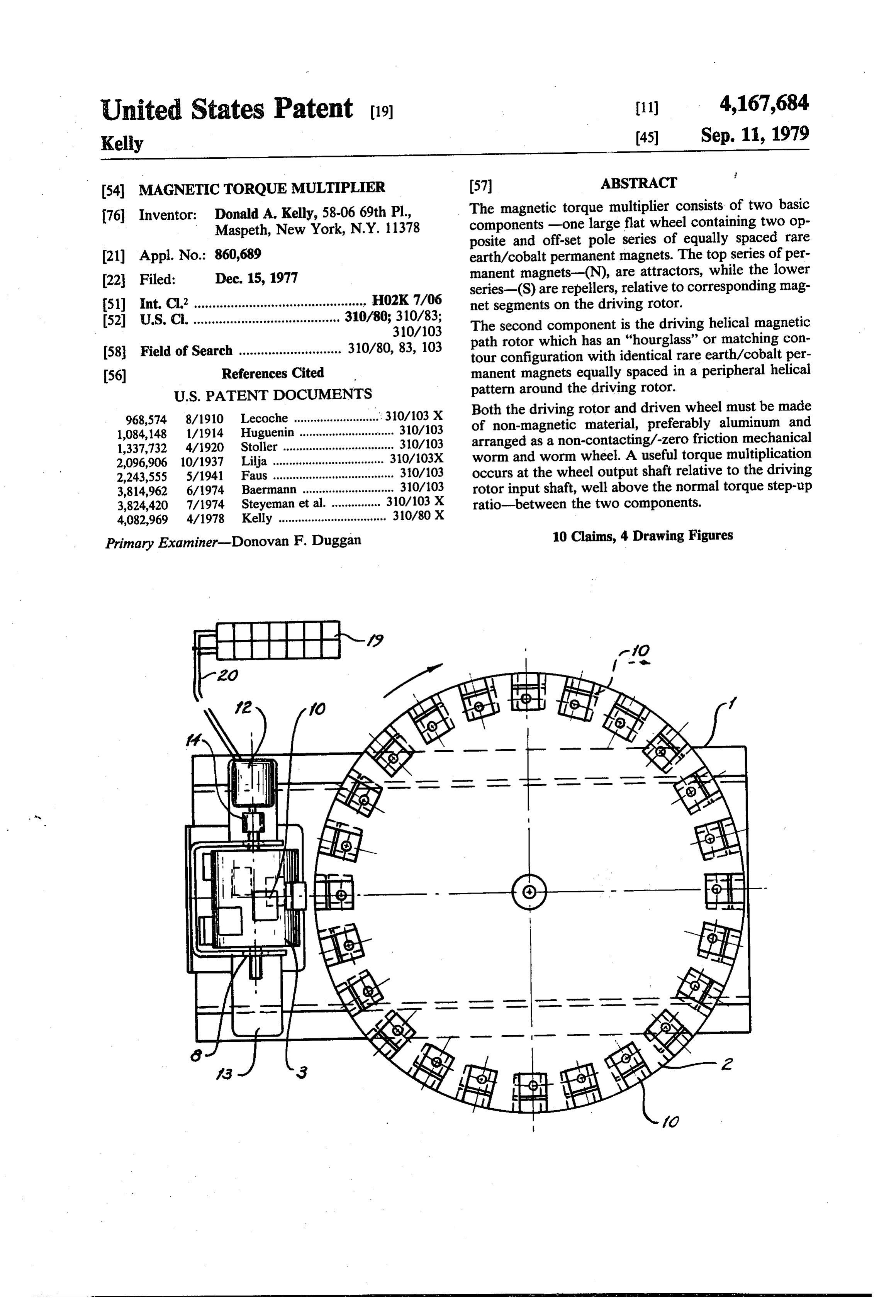
United States Patent (19) 11 4,167,684 Kelly (45) Sep. 11, 1979 54 MAGNETICTORQUE MULTIPLIER 57 ABSTRACT 76 Inventor: Donald A. Kelly, 58-06 69th Pl, The magnetic torque multiplier consists of two basic Maspeth, New York, N.Y. 11378 components -one large flat wheel containing two op posite and off-set pole series of equally spaced rare (21) Appl. No.: 860,689 earth/cobalt permanent magnets. The top series of per (22 Filed: Dec. 15, 1977 manent magnets-(N), are attractors, while the lower series-(S) are repellers, relative to corresponding mag 51) Int. C.’............................................... HO2K7/06 net segments on the driving rotor. 52 U.S. C. ........................................ 310/80; 310/83; The second component is the driving helical magnetic 310/103 path rotor which has an "hourglass' or matching con 58 Field of Search ............................ 310/80, 83, 103 tour configuration with identical rare earth/cobalt per 56) References Cited manent magnets equally spaced in a peripheral helical
968,574 8/1910 Lecoche .......................r 310/103 X Both the driving rotor and driven wheel must be made 1,084,148 1/1914 Huguenin ... ... 310/103 of non-magnetic material, preferably aluminum and 1,337,732 4/1920 Stoller .................................. 310/103 arranged as a non-contacting/-zero friction mechanical 2,096,906 10/1937 Lilja .................................. 310/103X worm and worm wheel. A useful torque multiplication 2,243,555 5/1941 Faus ..................................... 3.0/103 occurs at the wheel output shaft relative to the driving 3,814,962 6/1974 Baermann ....... . 310/103 rotor input shaft, well above the normal torque step-up 3,824,420 7/1974 Steyeman et al... . 30/103 X ratio-between the two components. 4,082,969 4/1978 Kelly ................................. 310/80 X
Primary Examiner-Donovan F. Duggan 10 Claims, 4 Drawing Figures
Page 2
Drawing sheet — no readable text.
Page 3
Drawing sheet — no readable text.
Page 4
attractive for achieving a practical magnetic torque
MAGNETICTORQUE MULTIPLIER multiplication unit. It is desirable to keep the magnet segment spacing close on the large wheel so that the the
BACKGROUND OF THE INVENTION multiple magnets on the small driving helical rotor can Numerous permanent magnet actuators, couplings 5 displace the wheel magnet segments in small increments with a corresponding large magnetic force between the and solenoid type motors have been advocated and built opposite magnet sets.
with the key objective of increasing the power output yield relative to the electrical power input, or magnetic A magnetic torque multiplier differs from the con advantage involved. Some of these devices consist of cept of a magnetic motor in regard to a self-starting multiple permanent magnets which are shifted or re- O feature and input torque. A magnetic torque multiplier volved, mechanically or electrically, in such away as to always requires a continuous input torque for the small cause continuous rotation or reciprocation. driving rotor, while a magnetic motor should always be None of these various devices and arrangements have self-starting with continuous self-sustained operation. become commercially successful because of their gener 15 The ideal magnetic torque multiplier provides a siz ally low-speed/-torque output and relatively poor cost able and useful torque step-up at the large wheel based Meffectiveness. Since all of these devices are essentially on the magnitude of the magnetic force between the low speed/torque units they cannot nearly compete opposite permanent magnet sets on each of the two with conventional high speed electric motors which are revolving components. An added advantage for this reliable and effective for practically all electrical power manner of magnetic force transfer using individual, applications. Since electric motors can easily be de 20 opposite magnetic segments is that no friction is im signed for all sorts of starting, load and environmental posed between the two components as in the case of the conditions they have naturally gained wide market mechanical contacting worm and worm wheel counter acceptance. The development of a practical and low parts. The helical magnetic rotor can run at high speed cost solenoid type of magnetic motor which is superior to the best electric motors is quite unlikely, as the rare 25 without surface contact, with a reduced-from-normal earth/cobalt permanent magnetic components come repulsion of torque rated input the due to alternating attraction and driven magnetic wheel acting on the into wide use for conventional electric motors.
rotor magnet segments.
Various types of permanent magnet, magnetic motors and powerful rare earth/cobalt It is most desirable to use large have been evolved with most of the designs based on 30 both opposite sets of magnetic components permanent magnets for reciprocating discs and linkage, with alternating shields large torque output differential between thetodriver achieve a and used to make and break the respective magnetic fields. driven shafts.
All of these known reciprocating units are impractical because of very short and non-linear power strokes, low torque The major difference between this present magnetic natural speed and cyclic torque output. Some of the multiplier-(M.T.M.) and the prior magnetic rotary types of permanent magnet "motors' being ad 35 torque converter,-(M.T.C.) is that a second, lower vocated are nothing more than magnetic couplings series of permanent magnet segments have been added since there is no direct and continuous magnetic lever to the wheel, as necessary second repulsion phase for age or torque stepup involved in their geometry. the driving rotor magnets in addition to the primary Any type of rotating magnetic geometry in which the attraction phase. It is most important that the magnet driven member-wheel can also drive the other member segments have a uniform magnetic force, plus coercive rotor can only have the value of a magnetic coupling force so that the torque input and output is smooth and since there is no torque increase with the important continuous, without any choppy and erratic rotation. element of a backstop or pawl action present. To be There are several important power applications wait practical, any magnetic torque multiplier using perma ing to be filled with effective, high-power magnetic nent magnets must provide both uniform attraction and 45 torque multipliers such as auxiliary home power replusion from high force magnets on a small diameter supplies, and practical, low-cost electric vehicles. At rotor to a large diameter magnetic segmented wheel. the present time the progress in the development of The small rotor should require a minimum of input practical electric vehicles is greatly impeded by lack of torque and the large wheel should not capable of back long-life, low-cost electric batteries. A high power revolving the small driving rotor. 50 magnetic torque multiplier can bridge the gap caused by
The magnetic couple described has a mechanical ineffective present batteries by providing a useful counterpart in the standard worm and worm wheel, power step-up from current batteries to the electric where a high speed worm drives a low speed wheel, and drive motor of the vehicle, to improve overall electric not visa-versa. For a single pitch worm there is a com vehicle operation and operating economics. plete backstopping action on the wheel and a high me 55 chanical advantage is produced. SUMMARY OF THE INVENTION Using the principle of the worm and worm wheel, a The magnetic torque multiplier is comprised of two practical magnetic torque multiplier is possible with rotating components, -one driving, small helical rotor attractive prospects for a useful torque stepup due to fitted with alternate attraction and repulsion between the opposite nets, whichidentical are rare earth/cobalt permanent mag equally spaced and form a continuous magnetic segments, although the magnet sets are re helical path around the rotor. The second component is volving at nearly right angles to each other, or exactly
a large, driven wheel which is fitted with corresponding
When a permanent magnet, magnetic torque multi equally spaced rare earth/cobalt magnets at the outside plier is arranged in this manner, with a small rare earth 65 diameter/periphery, on both surfaces of the wheel. The /cobalt magnetic rotor revolving at a right angle to a (lower) series of P/M's is slightly offset in a uniform large segmented rare-earth/cobalt magnetic wheel, and pattern around the circumference of the wheel in rela in-line with the plane of the wheel, then the geometry is tion to the (upper) series of P/M's in order to cause an
Page 5
added torque vector for the wheel as the rotor P/M's may be possible to gain some slight torque or speed repel each of the wheel's magnet segments. advantage by having the two rotating components It must be noted that the (lower) and (upper) series of skewed at an angle other than ninety degrees which will P/M's are only relative terms since the driven wheel be determined during continued development work. may operate in the vertical plane in which case the 5 It will be necessary to maintain close spacing, consis wheel magnet segments would be on either side of the tent with adjacent magnetic isolation, between the indi wheel. vidual magnet segments on both the small driving rotor Because of there placement of two opposite magnetic and large driven wheel to assure uniform segment dis pole series on both sides of the driven wheel, a toggle placement and an optimum dynamic magnetic force action zone is created as each driving rotor magnet 10 interaction between the two rotating components. segment approaches and passes the driven wheel plane. Each magnet segment may be directly bonded to a Although this toggle action zone is not desirable be non-magnetic wheel component, or may be clamped cause it tends to produce a cogging or jumping effect on onto the wheel with non-magnetic straps for ease of the rotor, it does produce the reduction in rated input replacement and dynamic balancing. The large driven torque for the driving rotor. 15 wheel must be rigid and rigidly mounted on large There is a definite continuous/-uniform "pull-push' thrust-type ball bearings for rigid, low-friction rotation. effect on the driving rotor as each rotor magnet seg Since the driving helical rotor will usually run at high ment moves toward and passes through the wheel speed, it is necessary to securely clamp on the magnet plane, due to the first attraction phase and second repul segments onto the non-magnetic helical rotor core, so sion phase of the double series of wheel magnet seg- 20 that they may be slightly shifted, but locked in place, to ments. maintain dynamic balance and retention, respectively. Without the second "repelling' series of wheel mag The driving helical rotor may be in cylindrical, single net segments, the pull of the first series of wheel magnet pitch form, or an "hourglass'-matching contour form segments must be broken by each rotor magnet seg for multiple single pitch design depending on the mag ment, which tends to cancel out the first 'attraction' 25 nitude of the output-torque requirements of the end phase, so that no reduction-from-normal input torque is application. The "hourglass'-matching contour driving possible with a single pole series of wheel magnet seg rotor will provide a proportional increase in output ments. torque due to the added number of rotor magnets which The second series of wheel repulsion magnet seg will influence the corresponding wheel magnet seg ments also adds to the wheel output torque since these 30 ments. As an example, -three helical loops of rotor wheel magnet segments are also repelled/reacted by magnets will nearly triple the torque output available at each rotor magnet segment as they pass the driven the wheel shaft.
wheel plane, due to the offset attitude of these segments The driving helical rotor must also be rigidly in relation to the first series of wheel magnet segments. mounted on high quality ball bearings to restrain the The primary wheel torque is produced by the uni- 35 reactions due to the dynamic magnetic interaction be form displacement of the adjacent wheel magnet seg tween the two magnetic components. The adjustable air ments as they are influenced by the uniform lateral gap of approximately 0.010 to 0.25 on the common displacement of each magnet segment of the rotor's centerline between the two rotating components must single pitch helical path. be held to this practical range in order to maintain the Although the latest rare earth/cobalt permanent 40 optimum interaction forces between the two sets of magnets are most desirable for the M.T.M. because of opposite revolving magnet segments.
their very high energy product and coercivity factor, Both the driving rotor core and matching driven the cost of these latest P/M's is correspondingly very wheel must be made from non-magnetic materials, pref. high. The use of Alnico V, VI, VII, or ceramic perma errably aluminum, so that the magnetic interaction be nent magnets has not necessarily been ruled out for this 45 tween the two components is not compromised in any application because of their competitive cost level and way.
reasonable operating characteristics. The permanent magnets selected for both rotating Since there is no practical size limitation to the con components must be uniformly identical and have the struction of an M.T.M., the conventional Alnico or highest possible energy product or magnetic induction ceramic permanent magnets may be used to advantage, 50 plus coercivity. Both of these magnetic properties, mag since they may be ganged together or selected and netic induction and coercive force will play a major arranged for the best magnetic interaction. For a given role in determining the true end value of the M.T.M. At input/output torque rating of a M.T.M., the permanent the present time the rare earth/cobalt permanent mag magnet cost will predominate the choice of the type of nets offer the highest possible magnetic properties for P/M selected, not necessarily the size of the M.T.M. 55 this application, but their cost is very high. Since costs unit. will also play a major role in the true value of the The multiple permanent magnet segments arrayed M.T.M.'s the magnets selected must show the highest with their common poles exposed as a single helical possible cost/effectiveness ratio, along with the longest path around the peripheral surface of the rotor are operating life.
known as-"inductors'. 60 Square or squarish, and flat rare earth/cobalt perma The (upper) series of P/M's are "attractors", while nent-magnets are presently preferred for this applica the (lower) series of P/M's are "repellers', relative to tion, and there is no theoretical limit to the size of both the corresponding, identical P/M's on the driving small interacting components. A practical limit to the actual rotor. size of the components is imposed by weight and mate The two components, -the driving helical rotor and 65 rial cost restrictions, plus available space, but nearly any the large driven wheel are arranged in a "worm and practical number or size of uniformly identical magnets worm-wheel' relationship, with the input and output may be used to make up the magnetic torque multiplier shaft axes at right angles, or nearly so, to each other. It components.
Page 6
The principal object of the invention is to provide the magnet segments 10, around the circumference of the highest torque output for the large, driven wheel from large wheel 2.
the lowest possible torque input for the small helical Each magnet segme:(10, is secured to the peripheral rotor, as a useful power step-up means for many electri surface of the small helical rotor 3, with non-magnetic cal generating applications. clamps 11, and standard non-magnetic hardware. The Another object of the invention is to provide a step magnetic segments 10, are equally and closely spaced up power source which can be produced at competitive around the rotor periphery and form a smooth helical costs, requires no combustible fuel and is non-polluting path around the rotor, which has a pitch which matches while running silently, and requires a minimum of parts the spacing between adjacent magnet segments 10, on replacement and maintenance. O the large driven wheel 2.
It is a further object of the invention is to provide a multiple The small, driving helical rotor 3, may consist of natural energy source which has an extremely long are helical loops of magnet segments 10a, which operating life, with a maximum of operating effective driven wheel 2,tosomatch contoured the outer radius of the large, that there are several rotor magnets ness and component resistance to degradation.
The various features of the invention with its basic S 10a, influencing the same number of corresponding design geometry will be more apparent from the follow multiple wheel magnet segments 10. The helical pitch of the ing description and drawings which illustrate the pre single helical helical loop rotor 3, would be the same as a ferred embodiment. It should be understood that varia magnetic loop rotor 3. The pitch tions may be made in the specific components, without 20 helical rotor 3, and of both components, the small, driving departing from the spirit and scope of the invention as determined by the optimum the large, driven wheel 2, will be described and illustrated.
spacing allowed between
Several Disclosure Documents have been filed with 2, adjacent magnet segments 10, on the large driven wheel the Office which describe the totality and portions of The small, driving helical rotor 3, is driven by any this magnetic torque multiplier: 25 suitable small D.C. or A.C. electric motor 12, which is No. 056,006-Permanent Magnet Device-(Dec. 7, secured to extension mounts 13, at the support bracket 1976) 9. The electric motor 12 may be connected to either side No. 064,353-Magnetic Torque Converter of the shaft 7, by means of the coupling 14, to provide No. 064,341-Compound Magnetic Torque Multi either direction of rotation for the small, driving helical plier 30 rotor 3.
No. 064,514-Magnetic Torque Multiplier. The support bracket 9, may be angularly rotated REFERRING TO THE DRAWINGS about the common magnetic centerline, at an angle other than ninety degrees between the axes of the two
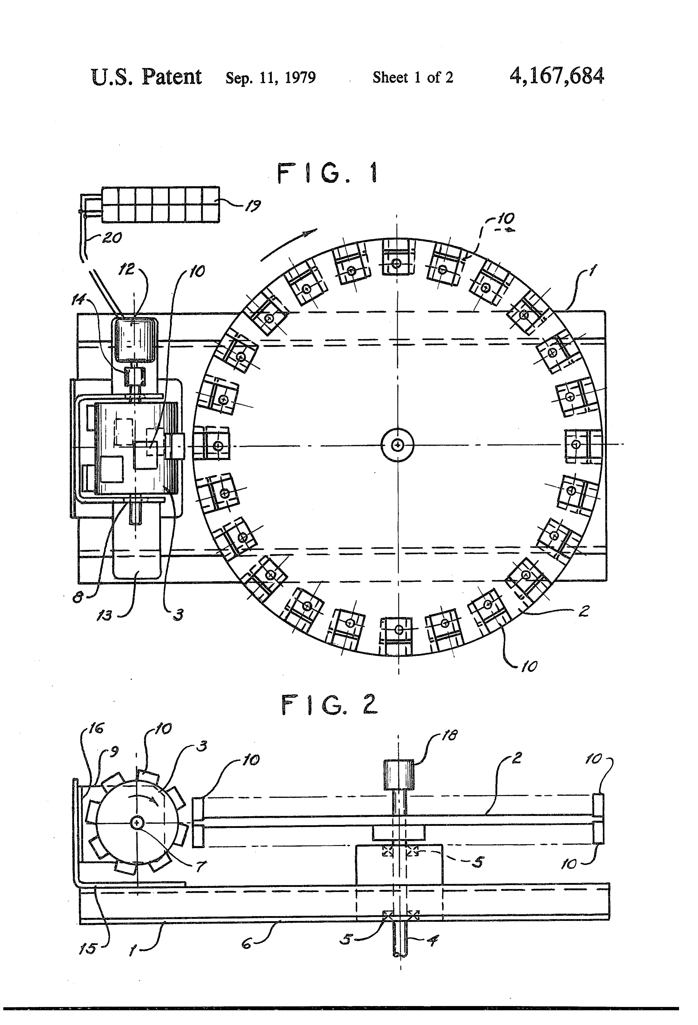
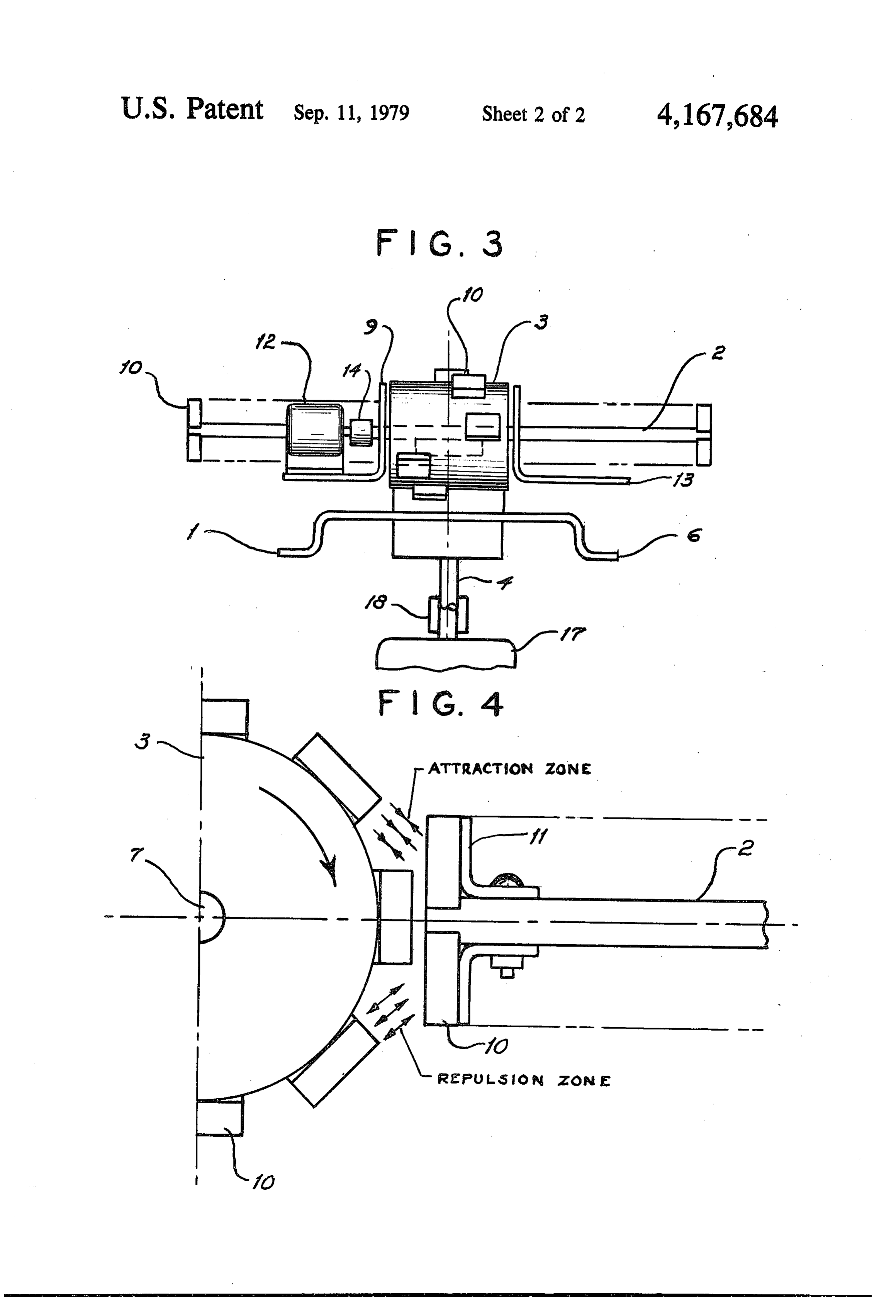
FIG. 1 is a top, external view of the magnetic torque revolving components 2 and 3. The support bracket 9, multiplier. 35 can be tilted as required, and locked on the end bracket FIG. 2 is an external side view of the magnetic torque 15, which is secured to the mounting base 6. A series of multiplier. corresponding holes 16, within both the support bracket FIG. 3 is an external end view of the magnetic torque 9, and the end bracket 15, allow the small, driving heli multiplier. cal rotor 3, to be set at a right angle, (in the end view), FIG. 4 is an enlarged local detail of the magnetic 40 or several other angles, in either direction, up to ap interaction between the magnetic rotor and wheel. proximately twenty degrees.
DESCRIPTION OF THE PREFERRED Standard mounting hardware is fitted into the se EMBODIMENT lected sets of corresponding holes 16, to securely lock the support bracket 9, to the end bracket 15.
The magnetic torque multiplier 1, is comprised of 45 Either end of the shaft 4, will be coupled to an elec two basic operating components which are the large, tric alternator or generator 17, by means of the coupling driven wheel 2, and the small, driving helical rotor 3, 18, which correspond to, and are arranged as a worm and The electric motor 12, as a D.C. type, can be pow worm wheel mechanical drive unit. Both the small ered by an array of solar photovoltaic cells 19, which driving helical rotor 3, and the large driven wheel2, are 50 may be remote-located but exposed to direct solar radi made of durable, non-magnetic materials. ation. Electrical leads 20, connect the solar cell array A shaft 4, and ball bearings 5, within a mounting base 19, to the D.C. electrical motor 12.
6, support the large, driven wheel 2, so that it revolves What is claimed is:
freely and transmits the output torque to the external 1. A magnetic torque multiplier comprised of two load. 55 basic rotating components,
A shaft 7, and ball bearings 8, within a support a large flat non-magnetic wheel containing two series bracket 9, support the small driving helical rotor 3, so of equally spaced identical permanent magnets that it revolves freely and transmits a continuous mag arrayed on each face of said flat non-magnetic netic influence to the large, driven wheel 2. wheel so that their opposite sets of common poles Each magnet segment 10, is secured to the large, 60 are exposed at the periphery, a slight uniform angu driven wheel2, with non-magnetic clamps 11, and stan lar offset between each of said two dard, non-magnetic hardware. The magnet segments series of equally spaced identical permanent magnets 10, preferrably of the rare earth/cobalt type are equally around the circumference of said large flat non spaced around each of the outer diameter faces of the magnetic wheel, wheel 2, and held to a spacing distance which is closely 65 a driving cylindrical non-magnetic rotor containing equal to the pitch of the small, driving helical rotor 3. multiple identical equally spaced permanent mag One face series of equally spaced magnet segments 10, is nets arrayed so that their common poles are ex slightly offset, in relation to the opposite face series of posed as a single pitch helical path on the periph
Page 7
eral surface of said driving cylindrical non-mag exposed as a single pitch helical path on the periph netic rotor, eral surface of said driving cylindrical non-mag arrangement of said large flat non-magnetic wheel netic rotor are known as "inductors', and said driving cylindrical non-magnetic rotor on the non-magnetic metal used for both said large flat a common centerline with the rotating shaft axes at 5 non-magnetic wheel and said driving cylindrical a right angle to each other, non-magnetic rotor is an aluminum alloy which is support means for said large flat non-magnetic wheel anodized and of a suitable temper. including an elongate base and shaft with ball bear 4. A magnetic torque multiplier according to claim 1, 1ngs, in which said large flat non-magnetic wheel is disposed support means for said driving cylindrical non-mag 10 in a vertical plane with said shaft axis on a horizontal netic rotor comprised of support brackets and shaft line, with two ball bearings, securing of said support said driving cylindrical non-magnetic rotor is dis brackets onto said elongate base, posed in a horizontal plane with said shaft axis on a securing and locking means for each of said equally vertical line, spaced identical permanent magnets onto said large 15 mounting of said support means for said large flat flat non-magnetic wheel and said driving cylindri non-magnetic wheel including an elongate base cal non-magnetic rotor, onto a suitable vertical surface, electric motor drive means for the shaft of said driv standard hareware securing means for the mounting ing-cylindrical non-magnetic rotor, a coupling se of said support means.
curing said electric motor drive means to said shaft 20 5. A magnetic torque multiplier according to claim 1, of said driving cylindrical non-magnetic rotor, in which said equally spaced identical permanent mag an alternator coupled to said shaft of said large flat nets arrayed on each face of said large flat non-magnetic non-magnetic wheel, wheel are arranged with optimum adjacent spacing multiple solar photovoltaic cells remotely connected determined by a minimum of magnetic interaction be to said electric motor drive means, connection of 25 tween adjacent magnets, said multiple solar photovoltaic cells to said elec the optimum adjacent spacing becomes known as the tric motor drive means with suitable multiple elec pitch of said large flat non-magnetic wheel, tric conduction wires. the pitch of the large flat non-magnetic wheel is equal 2. A magnetic torque multiplier according to claim 1, to the single pitch of said driving cylindrical non in which said equally spaced identical permanent mag 30 magnetic rotor, nets are squarish and flat and made of rare earth cobalt the single pitch helical path on the peripheral surface materials, of said driving cylindrical non-magnetic rotor is said equally spaced identical permanent magnets equal to the pitch of said large flat non-magnetic range in size and force from 16 to 18 BH wheel.
max.x 106 Gauss Oersteds as the normal peak en 35 6. A magnetic torque multiplier comprised of two ergy product and have residual induction from basic rotating magnetic components, 8,000 to 8,500 Gauss, a large flat non-magnetic wheel containing two series a coercive force range of from 7,000 to 8,000 Oer of equally spaced identical permanent magnets steds, arrayed on each face of said large flat non-mag mounting of said multiple equally spaced identical netic wheel so that their opposite sets of north permanent magnets with their flat faces exposed at south common poles are exposed at the periphery, the peripheries of said large flat non-magnetic a uniform angular offset between each of said two wheel and said driving cylindrical non-magnetic series of equally spaced identical permanent mag rotor. nets around the circumference of said large flat 3. A magnetic torque multiplier according to claim 1, 45 non-magnetic wheel, wherein said equally spaced identical permanent mag a small diameter driving non-magnetic rotor of an nets arrayed on each face of said large flat non-magnetic "hourglass' contour form containing multiple wheel are arranged so the the top series of equally identical equally spaced permanent magnets ar spaced identical permanent magnets have common rayed so that their common poles are exposed as a north (N) poles exposed at the periphery, 50 multiple helical path on the peripheral surface of the bottom series of equally spaced identical perma said driving non-magnetic rotor, nent magnets have common south (S) poles ex arrangement of said large flat non-magnetic wheel posed at the periphery, and said driving non-magnetic rotor on a common the said driving cylindrical non-magnetic rotor con centerline with the rotating shaft axes at a right taining multiple identical equally spaced perma 55 angle to each other, nent magnets arrayed so that their common south support means for said large flat non-magnetic wheel (S) poles are exposed as a single pitch helical path comprised of an elongate formed sheet metal base on the peripheral surface of said driving cylindrical and shaft with two ball bearings of the thrust type, non-magnetic rotor, support means for said driving non-magnetic rotor the top series of said equally spaced identical perma comprised of support brackets and shaft with two nent magnets arrayed on the top face of said large ball bearings, securing of said support brackets flat non magnetic wheel are known as "attractors', onto said elongate formed-sheet metal base, the bottom series of said equally spaced identical securing and locking means for each of said equally permanent magnets arrayed on the bottom face of spaced identical permanent magnets onto said large said large flat non-magnetic wheel are known as 65 flat non-magnetic wheel and said driving non-mag “repellers”, netic rotor, said multiple identical equally spaced permanent A.C. electric moter drive means for the shaft of said magnets arrayed so that their common poles are driving non-magnetic rotor, a coupling connecting
Page 8
means for said driving non-magnetic rotor and said nent magnets have common north (N) poles exposed at A.C. electric motor, the periphery, a generator coupled to said large flat non-magnetic the bottom series of equally spaced identical perma wheel. nent magnets have common south (S) poles ex 7. A magnetic torque multiplier according to claim 6, posed at the periphery, the small diameter driving non-magnetic rotor of an in which said small diameter driving non-magnetic hour-glass contour form containing multiple identi rotor of an hour-glass contour form matches the radius cal equally spaced permanent magnets arrayed so of said large flat non-magnetic wheel, the pitch of said that their common south-(S) poles are exposed as a small diameter driving non-magnetic rotor is single and 10 multiple helical loop path on the peripheral surface matches the pitch-spacing between adjacent magnets on of said driving non-magnetic rotor. said large flat non-magnetic wheel, 10. A magnetic torque multiplier according to claim said small diameter driving non-magnetic rotor has a 6, in which minimum of three helical continuous loops and a 15 said large flat non-magnetic wheel is disposed in a maximum of eight helical continuous loops. vertical plane with the shaft axis in a horizontal 8. A magnetic torque multiplier according to claim 6, line, in which said equally spaced identical permanent mag said driving non-magnetic rotor is disposed in a hori nets are square and flat and made of conventional ce zontal plane with the shaft axis in a vertical line, mounting od said support means for said large flat ramic or Alnico magnetic materials, maximum perma 20 non-magnetic wheel onto a suitable vertical sur nent magnetic operating characteristics for each of said face, equally spaced identical permanent magnets. said equally spaced identical permanent magnets ar 9. A magnetic torque multiplier according to claim 6, rayed on each face of said large flat non-magnetic wherein said equally spaced identical permanent mag wheel are arranged with optimum adjacent spacing nets arrayed on on each face of said large flat non-mag 25 determined by a minimum
of skmagnetic interaction.
netic wheel are arranged so that the top series of perma
Provenance
- Collection
- Cited prior art
- Original PDF
- patentimages.storage.googleapis.com →
- Filed
- 1977-12-15
- Pages
- 8
- Method
- pdftotext (the PDF's own text layer) + pdftoppm 300dpi page scans
- Source
- Google Patents bibliographic record
- Granted
- 1979-09-11
- Inventors
- Donald A. Kelly
- Transcribed from
- patentimages.storage.googleapis.com →