patent · US3573517
Magnetic drive
6 April 1971
Page 1 — bibliographic record
United States Patent (11) 3,573,517 72 Inventor Gordon E. Osterstrom Primary Examiner-D. X. Sliney Winnetka, Ill. Attorney-Greist, Lockwood, Greenawalt & Dewey
(73) Assignee Sargent-Welch Scientific Company ABSTRACT: A synchronous magnetic drive for transmission Skokie, Ill.
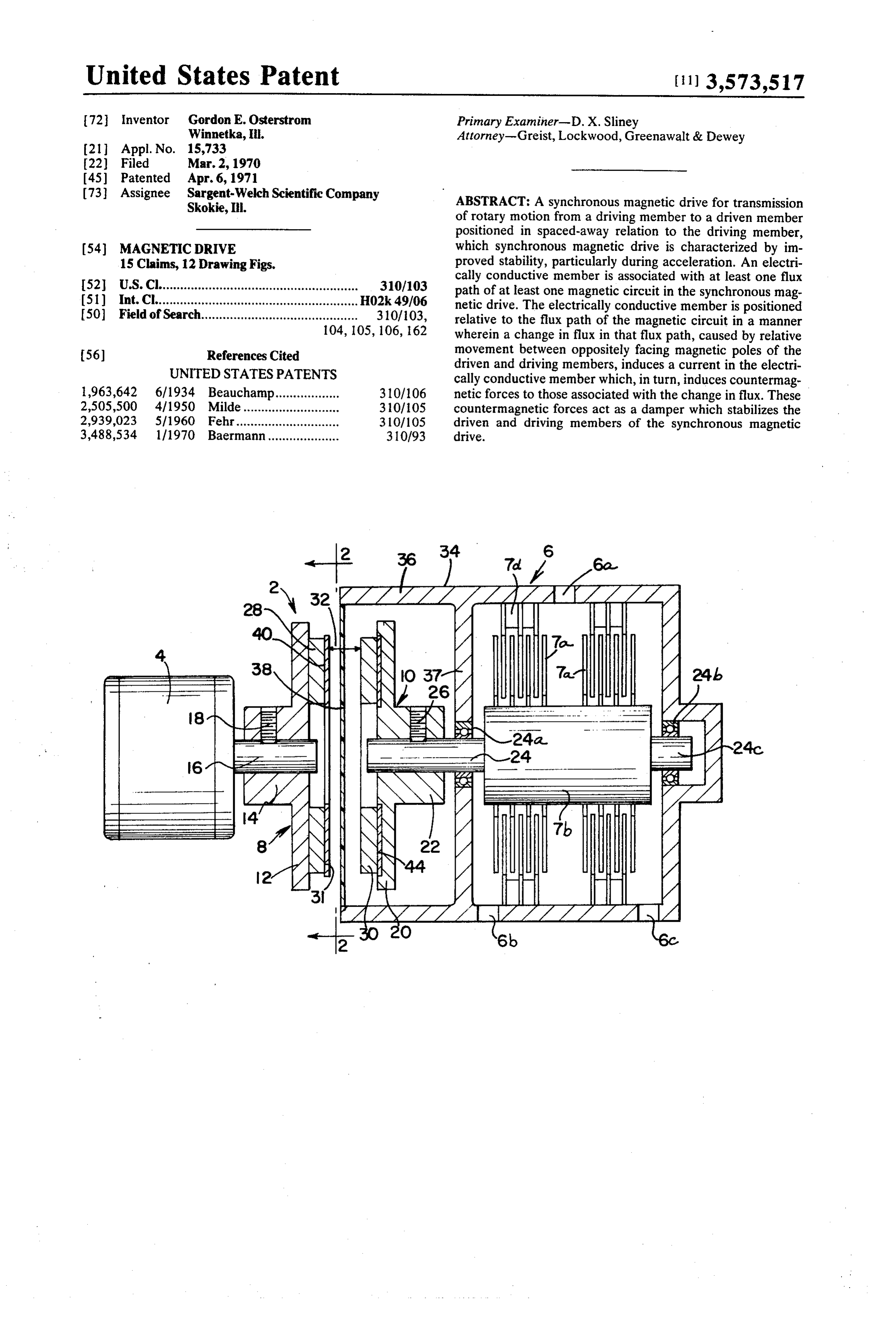
of rotary motion from a driving member to a driven member positioned in spaced-away relation to the driving member, (54) MAGNETIC DRIVE which synchronous magnetic drive is characterized by im 15 Claims, 12 Drawing Figs. proved stability, particularly during acceleration. An electri 52 U.S. Cl........................................................ 310/103 cally conductive member is associated with at least one flux path of at least one magnetic circuit in the synchronous mag (51) int. Cli........................................................ H02k 49/06 netic drive. The electrically conductive member is positioned 50 Field of Search............................................ 310/103, relative to the flux path of the magnetic circuit in a manner 104, 105,106, 162 wherein a change in flux in that flux path, caused by relative 56) References Cited movement between oppositely facing magnetic poles of the UNITED STATES PATENTS driven and driving members, induces a current in the electri cally conductive member which, in turn, induces countermag 1963,642 6/1934 Beauchamp.................. 310/106 netic forces to those associated with the change in flux. These 2,505,500 4/1950 Milde............ 310/105 countermagnetic forces act as a damper which stabilizes the 2,939,023 5/1960 Fehr.......... 310/105 driven and driving members of the synchronous magnetic 3,488,534 1/1970 Baermann.................... 310/93 drive.
Page 2
Drawing sheet — no readable text.
Page 3
Drawing sheet — no readable text.
Page 4
Drawing sheet — no readable text.
Page 5
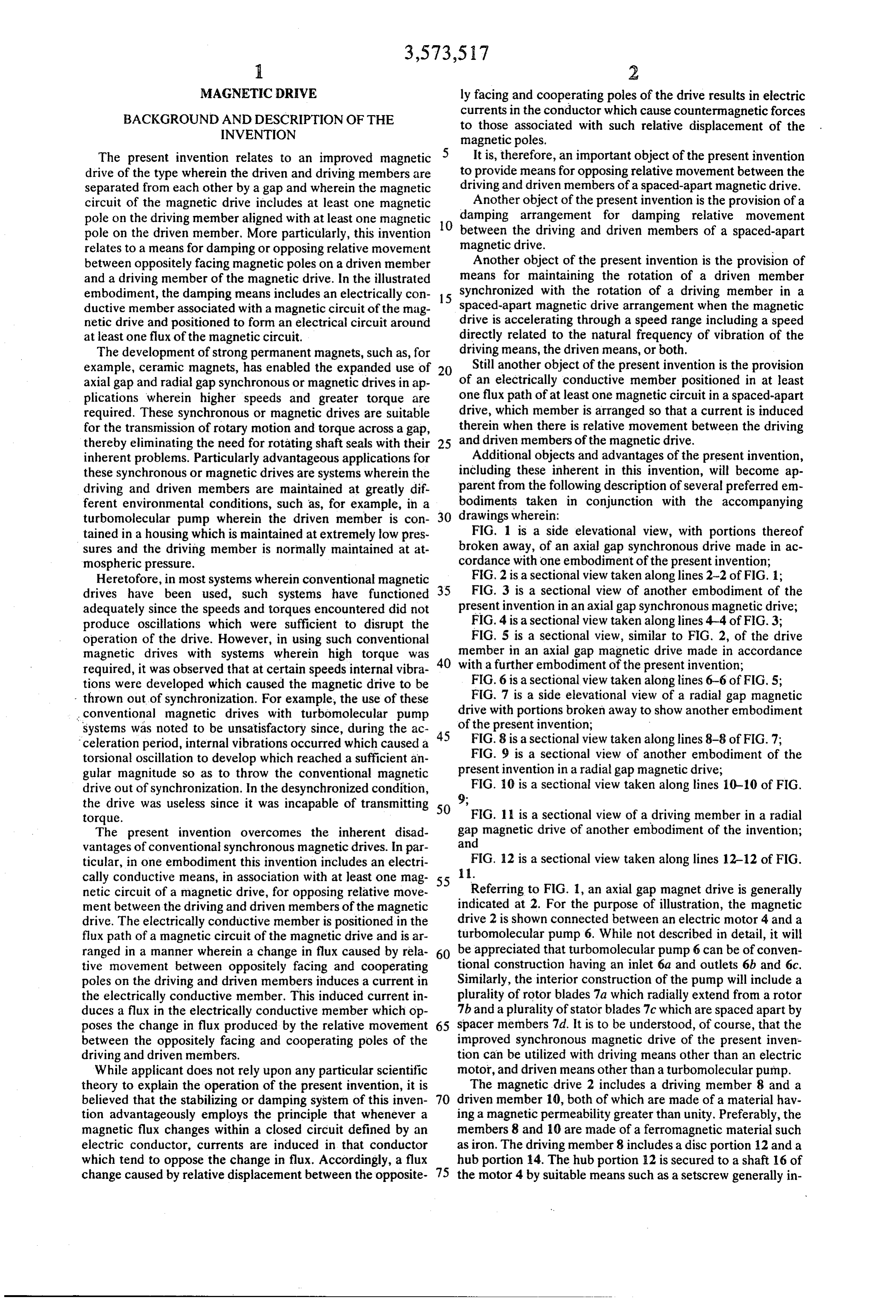
MAGNETIC DRIVE ly facing and cooperating poles of the drive results in electric BACKGROUND AND DESCRIPTION OF THE currents in the conductor which cause countermagnetic forces INVENTION to those associated with such relative displacement of the magnetic poles.
The present invention relates to an improved magnetic It is, therefore, an important object of the present invention drive of the type wherein the driven and driving members are to provide means for opposing relative movement between the separated from each other by a gap and wherein the magnetic driving and driven members of a spaced-apart magnetic drive. circuit of the magnetic drive includes at least one magnetic Another object of the present invention is the provision of a pole on the driving member aligned with at least one magnetic damping arrangement for damping relative movement O between the driving and driven members of a spaced-apart pole on the driven member. More particularly, this invention relates to a means for damping or opposing relative movement magnetic drive.
between oppositely facing magnetic poles on a driven member Another object of the present invention is the provision of and a driving member of the magnetic drive. In the illustrated means for maintaining the rotation of a driven member embodiment, the damping means includes an electrically con 15 synchronized with the rotation of a driving member in a ductive member associated with a magnetic circuit of the mag spaced-apart magnetic drive arrangement when the magnetic netic drive and positioned to form an electrical circuit around drive is accelerating through a speed range including a speed at least one flux of the magnetic circuit. directly related to the natural frequency of vibration of the The development of strong permanent magnets, such as, for driving means, the driven means, or both.
example, ceramic magnets, has enabled the expanded use of Still another object of the present invention is the provision axial gap and radial gap synchronous or magnetic drives in ap of an electrically conductive member positioned in at least plications wherein higher speeds and greater torque are one flux path of at least one magnetic circuit in a spaced-apart required. These synchronous or magnetic drives are suitable drive, which member is arranged so that a current is induced for the transmission of rotary motion and torque across a gap, therein when there is relative movement between the driving thereby eliminating the need for rotating shaft seals with their 25 and driven members of the magnetic drive. inherent problems. Particularly advantageous applications for Additional objects and advantages of the present invention, these synchronous or magnetic drives are systems wherein the including these inherent in this invention, will become ap driving and driven members are maintained at greatly dif parent from the following description of several preferred em ferent environmental conditions, such as, for example, in a bodiments taken in conjunction with the accompanying turbomolecular pump wherein the driven member is con drawings wherein:
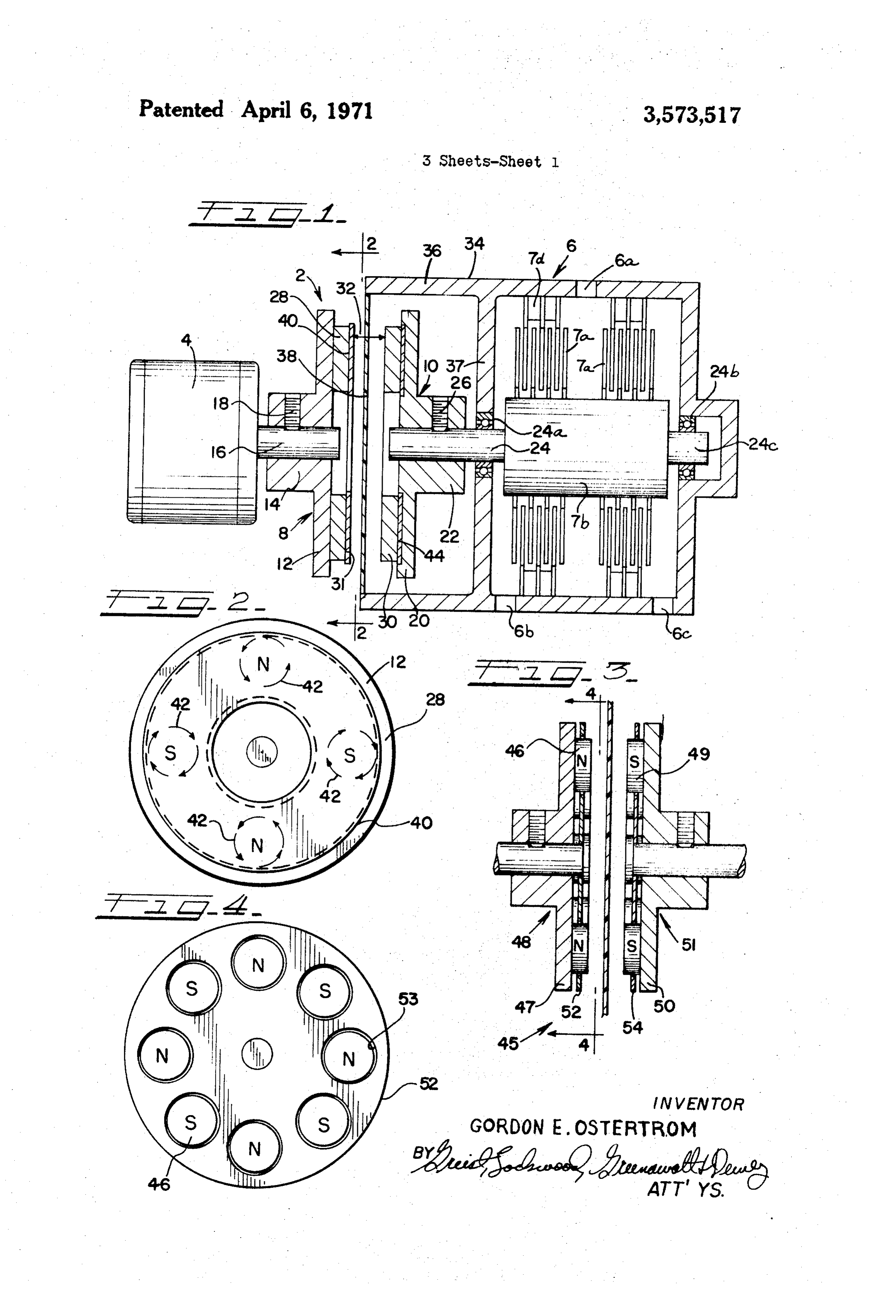
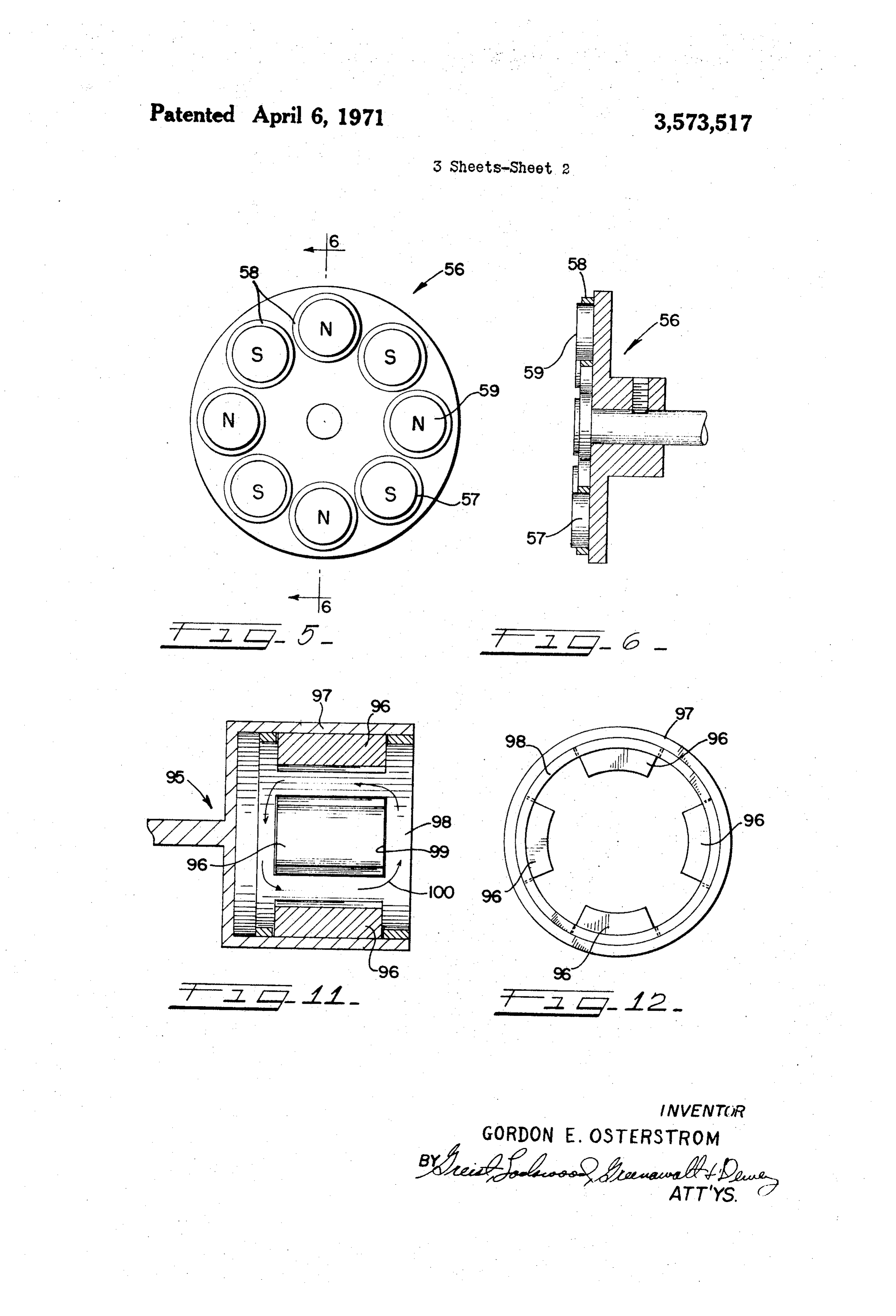
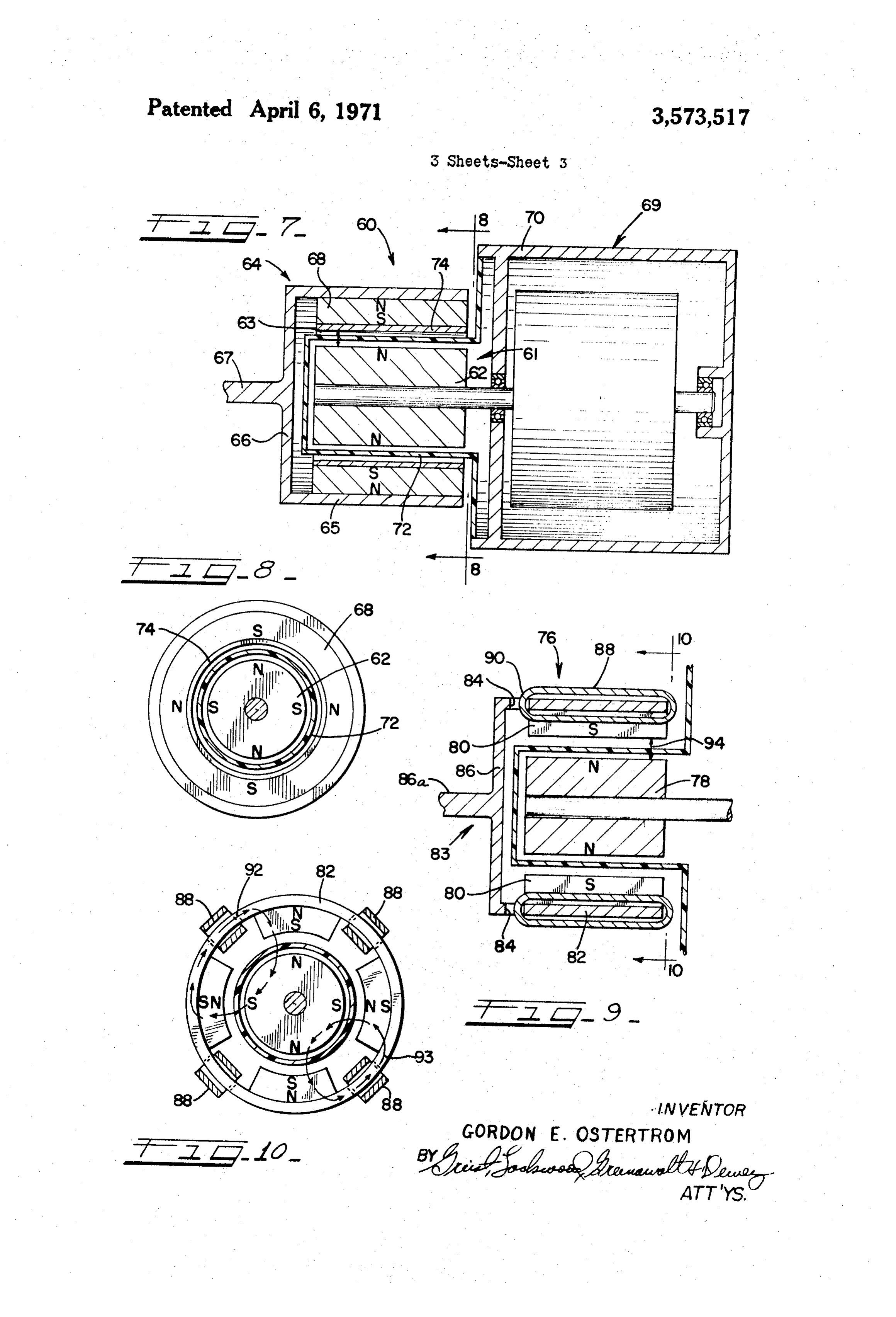
tained in a housing which is maintained at extremely low pres FIG. 1 is a side elevational view, with portions thereof sures and the driving member is normally maintained at at broken away, of an axial gap synchronous drive made in ac mospheric pressure. cordance with one embodiment of the present invention; Heretofore, in most systems wherein conventional magnetic FIG. 2 is a sectional view taken along lines 2-2 of FIG. 1; drives have been used, such systems have functioned 35 FIG. 3 is a sectional view of another embodiment of the adequately since the speeds and torques encountered did not present invention in an axial gap synchronous magnetic drive; produce oscillations which were sufficient to disrupt the FIG. 4 is a sectional view taken along lines 4-4 of FIG.3; operation of the drive. However, in using such conventional FIG. 5 is a sectional view, similar to FIG. 2, of the drive magnetic drives with systems wherein high torque was 40 member in an axial gap magnetic drive made in accordance required, it was observed that at certain speeds internal vibra with a further embodiment of the present invention; tions were developed which caused the magnetic drive to be FIG. 6 is a sectional view taken along lines 6-6 of FIG. 5; - thrown out of synchronization. For example, the use of these FIG. 7 is a side elevational view of a radial gap magnetic conventional magnetic drives with turbomolecular pump drive with portions broken away to show another embodiment systems was noted to be unsatisfactory since, during the ac 45 of the present invention;
celeration period, internal vibrations occurred which caused a FIG. 8 is a sectional view taken along lines 8–8 of FIG.7; torsional oscillation to develop which reached a sufficient an FIG. 9 is a sectional view of another embodiment of the gular magnitude so as to throw the conventional magnetic present invention in a radial gap magnetic drive; drive out of synchronization. In the desynchronized condition, FIG. 10 is a sectional view taken along lines 10-10 of FIG. the drive was useless since it was incapable of transmitting 50 9;
torque. FIG. 1 is a sectional view of a driving member in a radial The present invention overcomes the inherent disad gap magnetic drive of another embodiment of the invention; vantages of conventional synchronous magnetic drives. In par and ticular, in one embodiment this invention includes an electri FIG. 12 is a sectional view taken along lines 12-12 of FIG. cally conductive means, in association with at least one mag 55 .
netic circuit of a magnetic drive, for opposing relative move Referring to FIG. 1, an axial gap magnet drive is generally ment between the driving and driven members of the magnetic indicated at 2. For the purpose of illustration, the magnetic drive. The electrically conductive member is positioned in the drive 2 is shown connected between an electric motor 4 and a flux path of a magnetic circuit of the magnetic drive and is ar turbomolecular pump 6. While not described in detail, it will ranged in a manner wherein a change in flux caused by rela 60 be appreciated that turbomolecular pump 6 can be of conven tive movement between oppositely facing and cooperating tional construction having an inlet 6a and outlets 6b and 6c. poles on the driving and driven members induces a current in Similarly, the interior construction of the pump will include a the electrically conductive member. This induced current in plurality of rotor blades 7a which radially extend from a rotor duces a flux in the electrically conductive member which op 7b and a plurality of stator blades 7c which are spaced apart by poses the change in flux produced by the relative movement 65 spacer members 7d. It is to be understood, of course, that the between the oppositely facing and cooperating poles of the improved synchronous magnetic drive of the present inven driving and driven members. tion can be utilized with driving means other than an electric While applicant does not rely upon any particular scientific motor, and driven means other than a turbomolecular pump. theory to explain the operation of the present invention, it is The magnetic drive 2 includes a driving member 8 and a believed that the stabilizing or damping system of this inven 70 driven member 10, both of which are made of a material hav tion advantageously employs the principle that whenever a ing a magnetic permeability greater than unity. Preferably, the magnetic flux changes within a closed circuit defined by an members 8 and 10 are made of a ferromagnetic material such electric conductor, currents are induced in that conductor as iron. The driving member 8 includes a disc portion 12 and a which tend to oppose the change in flux. Accordingly, a flux hub portion 14. The hub portion 2 is secured to a shaft 16 of change caused by relative displacement between the opposite 75 the motor 4 by suitable means such as a setscrew generally in
Page 6
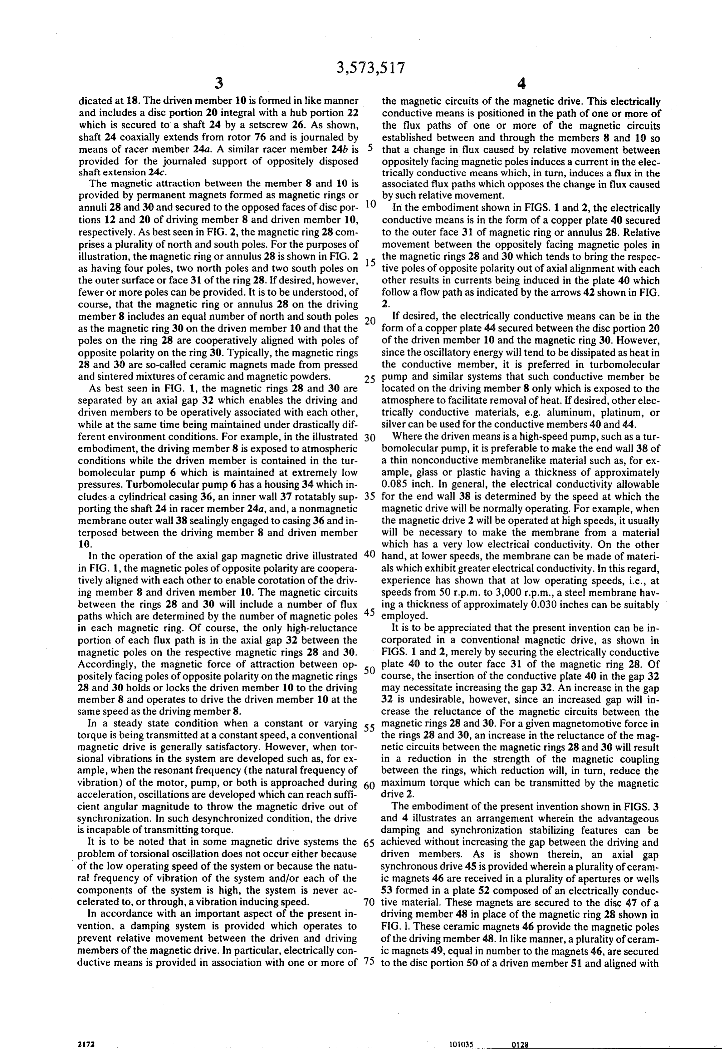
dicated at 8. The driven member 10 is formed in like manner the magnetic circuits of the magnetic drive. This electrically and includes a disc portion 20 integral with a hub portion 22 conductive means is positioned in the path of one or more of which is secured to a shaft 24 by a setscrew 26. As shown, the flux paths of one or more of the magnetic circuits shaft 24 coaxially extends from rotor 76 and is journaled by established between and through the members 8 and 10 so means of racer member 24a. A similar racer member 24b is that a change in flux caused by relative movement between provided for the journaled support of oppositely disposed oppositely facing magnetic poles induces a current in the elec shaft extension 24c. trically conductive means which, in turn, induces a flux in the The magnetic attraction between the member 8 and 10 is associated flux paths which opposes the change in flux caused provided by permanent magnets formed as magnetic rings or by such relative movement.
annuli 28 and 30 and secured to the opposed faces of disc por O In the embodiment shown in FIGS. 1 and 2, the electrically tions 12 and 20 of driving member 8 and driven member 10, conductive means is in the form of a copper plate 40 secured respectively. As best seen in FIG. 2, the magnetic ring 28 com to the outer face 31 of magnetic ring or annulus 28. Relative prises a plurality of north and south poles. For the purposes of movement between the oppositely facing magnetic poles in illustration, the magnetic ring or annulus 28 is shown in FIG. 2 15 the magnetic rings 28 and 30 which tends to bring the respec as having four poles, two north poles and two south poles on tive poles of opposite polarity out of axial alignment with each the outer surface or face 31 of the ring 28. If desired, however, other results in currents being induced in the plate 40 which fewer or more poles can be provided. It is to be understood, of follow a flow path as indicated by the arrows 42 shown in FIG. course, that the magnetic ring or annulus 28 on the driving 2.
member 8 includes an equal number of north and south poles 20 If desired, the electrically conductive means can be in the as the magnetic ring 30 on the driven member 10 and that the form of a copper plate 44 secured between the disc portion 20 poles on the ring 28 are cooperatively aligned with poles of of the driven member 10 and the magnetic ring 30. However, opposite polarity on the ring 30. Typically, the magnetic rings since the oscillatory energy will tend to be dissipated as heat in 28 and 30 are so-called ceramic magnets made from pressed the conductive member, it is preferred in turbomolecular and sintered mixtures of ceramic and magnetic powders. 25 pump and similar systems that such conductive member be As best seen in FIG. 1, the magnetic rings 28 and 30 are located on the driving member 8 only which is exposed to the separated by an axial gap 32 which enables the driving and atmosphere to facilitate removal of heat. If desired, other elec driven members to be operatively associated with each other, trically conductive materials, e.g. aluminum, platinum, or while at the same time being maintained under drastically dif silver can be used for the conductive members 40 and 44. ferent environment conditions. For example, in the illustrated 30 Where the driven means is a high-speed pump, such as a tur embodiment, the driving member 8 is exposed to atmospheric bomolecular pump, it is preferable to make the end wall 38 of conditions while the driven member is contained in the tur a thin nonconductive membranelike material such as, for ex bomolecular pump 6 which is maintained at extremely low ample, glass or plastic having a thickness of approximately pressures. Turbomolecular pump 6 has a housing 34 which in 0.085 inch. In general, the electrical conductivity allowable cludes a cylindrical casing 36, an inner wall 37 rotatably sup 35 for the end wall 38 is determined by the speed at which the porting the shaft 24 in racer member 24a, and, a nonmagnetic magnetic drive will be normally operating. For example, when membrane outer wall 38 sealingly engaged to casing 36 and in the magnetic drive 2 will be operated at high speeds, it usually terposed between the driving member 8 and driven member will be necessary to make the membrane from a material 10. which has a very low electrical conductivity. On the other In the operation of the axial gap magnetic drive illustrated 40 hand, at lower speeds, the membrane can be made of materi in FIG. 1, the magnetic poles of opposite polarity are coopera als which exhibit greater electrical conductivity. In this regard, tively aligned with each other to enable corotation of the driv experience has shown that at low operating speeds, i.e., at ing member 8 and driven member 10. The magnetic circuits speeds from 50 r.p.m. to 3,000 rp.m., a steel membrane hav between the rings 28 and 30 will include a number of flux 45 ing a thickness of approximately 0.030 inches can be suitably paths which are determined by the number of magnetic poles employed.
in each magnetic ring. Of course, the only high-reluctance It is to be appreciated that the present invention can be in portion of each flux path is in the axial gap 32 between the corporated in a conventional magnetic drive, as shown in magnetic poles on the respective magnetic rings 28 and 30. FIGS. 1 and 2, merely by securing the electrically conductive Accordingly, the magnetic force of attraction between op 50 plate 40 to the outer face 31 of the magnetic ring 28. Of positely facing poles of opposite polarity on the magnetic rings course, the insertion of the conductive plate 40 in the gap 32 28 and 30 holds or locks the driven member 10 to the driving may necessitate increasing the gap 32. An increase in the gap member 8 and operates to drive the driven member 10 at the 32 is undesirable, however, since an increased gap will in same speed as the driving member 8. crease the reluctance of the magnetic circuits between the In a steady state condition when a constant or varying 55 magnetic rings 28 and 30. For a given magnetomotive force in torque is being transmitted at a constant speed, a conventional the rings 28 and 30, an increase in the reluctance of the mag magnetic drive is generally satisfactory. However, when tor netic circuits between the magnetic rings 28 and 30 will result sional vibrations in the system are developed such as, for ex in a reduction in the strength of the magnetic coupling ample, when the resonant frequency (the natural frequency of between the rings, which reduction will, in turn, reduce the vibration) of the motor, pump, or both is approached during 60 maximum torque which can be transmitted by the magnetic acceleration, oscillations are developed which can reach suffi drive 2.
cient angular magnitude to throw the magnetic drive out of The embodiment of the present invention shown in FIGS. 3 synchronization. In such desynchronized condition, the drive and 4 illustrates an arrangement wherein the advantageous is incapable of transmitting torque. damping and synchronization stabilizing features can be It is to be noted that in some magnetic drive systems the 65 achieved without increasing the gap between the driving and problem of torsional oscillation does not occur either because driven members. As is shown therein, an axial gap of the low operating speed of the system or because the natu synchronous drive 45 is provided wherein a plurality of ceram ral frequency of vibration of the system and/or each of the ic magnets 46 are received in a plurality of apertures or wells components of the system is high, the system is never ac 53 formed in a plate 52 composed of an electrically conduc celerated to, or through, a vibration inducing speed. 70 tive material. These magnets are secured to the disc 47 of a In accordance with an important aspect of the present in driving member 48 in place of the magnetic ring 28 shown in vention, a damping system is provided which operates to FIG. I. These ceramic magnets 46 provide the magnetic poles prevent relative movement between the driven and driving of the driving member 48. In like manner, a plurality of ceram members of the magnetic drive. In particular, electrically con ic magnets 49, equal in number to the magnets 46, are secured ductive means is provided in association with one or more of 75 to the disc portion 50 of a driven member 51 and aligned with
2 1) 1035 28
Page 7
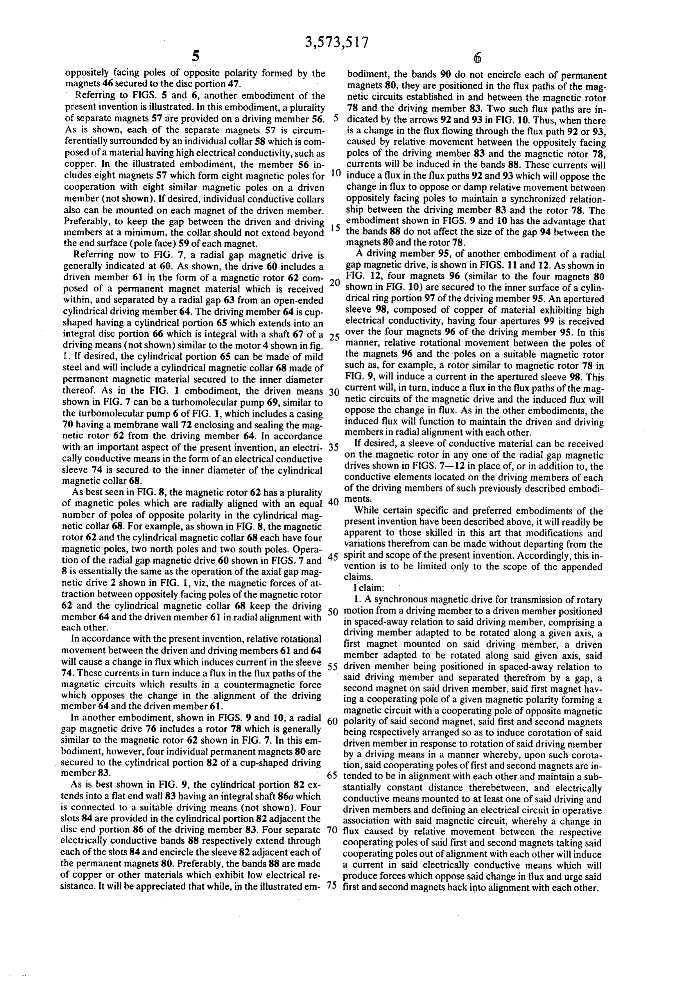
S 6 oppositely facing poles of opposite polarity formed by the bodiment, the bands 90 do not encircle each of permanent magnets 46 secured to the disc portion 47. magnets 80, they are positioned in the flux paths of the mag Referring to FIGS. 5 and 6, another embodiment of the netic circuits established in and between the magnetic rotor present invention is illustrated. In this embodiment, a plurality 78 and the driving member 83. Two such flux paths are in of separate magnets 57 are provided on a driving member 56. dicated by the arrows 92 and 93 in FIG. 10. Thus, when there As is shown, each of the separate magnets 57 is circum is a change in the flux flowing through the flux path 92 or 93, ferentially surrounded by an individual collar 58 which is com caused by relative movement between the oppositely facing posed of a material having high electrical conductivity, such as poles of the driving member 83 and the magnetic rotor 78, copper. In the illustrated embodiment, the member 56 in 10 currents will be induced in the bands 88. These currents will cludes eight magnets 57 which form eight magnetic poles for induce a flux in the flux paths 92 and 93 which will oppose the cooperation with eight similar magnetic poles on a driven change in flux to oppose or damp relative movement between member (not shown). If desired, individual conductive collars oppositely facing poles to maintain a synchronized relation also can be mounted on each magnet of the driven member. ship between the driving member 83 and the rotor 78. The Preferably, to keep the gap between the driven and driving 15 embodiment shown in FIGS. 9 and 10 has the advantage that members at a minimum, the collar should not extend beyond the bands 88 do not affect the size of the gap 94 between the the end surface (pole face) 59 of each magnet. magnets 80 and the rotor 78.
Referring now to FIG. 7, a radial gap magnetic drive is A driving member 95, of another embodiment of a radial generally indicated at 60. As shown, the drive 60 includes a gap magnetic drive, is shown in FIGS. 11 and 12. As shown in driven member 61 in the form of a magnetic rotor 62 com FIG. 12, four magnets 96 (similar to the four magnets 80 posed of a permanent magnet material which is received 20 shown in FIG. 10) are secured to the inner surface of a cylin within, and separated by a radial gap 63 from an open-ended drical ring portion 97 of the driving member 95. An apertured cylindrical driving member 64. The driving member 64 is cup sleeve 98, composed of copper of material exhibiting high shaped having a cylindrical portion 65 which extends into an electrical conductivity, having four apertures 99 is received integral disc portion 66 which is integral with a shaft 67 of a 25 over the four magnets 96 of the driving member 95. In this driving means (not shown) similar to the motor 4 shown in fig. manner, relative rotational movement between the poles of 1. If desired, the cylindrical portion 65 can be made of mild the magnets 96 and the poles on a suitable magnetic rotor such as, for example, a rotor similar to magnetic rotor 78 in steel and will include a cylindrical magnetic collar 68 made of permanent magnetic material secured to the inner diameter FIG. 9, will induce a current in the apertured sleeve 98. This thereof. As in the FIG. embodiment, the driven means 30 current will, in turn, induce a flux in the flux paths of the mag shown in FIG. 7 can be a turbomolecular pump 69, similar to netic circuits of the magnetic drive and the induced flux will the turbomolecular pump 6 of FIG. 1, which includes a casing oppose the change in flux. As in the other embodiments, the 70 having a membrane wall 72 enclosing and sealing the mag induced flux will function to maintain the driven and driving netic rotor 62 from the driving member 64. In accordance members in radial alignment with each other. with an important aspect of the present invention, an electri 35 onIfthe desired, a sleeve of conductive material can be received magnetic rotor in any one of the radial gap magnetic cally conductive means in the form of an electrical conductive drives shown in FIGS. 7-12 in place of, or in addition to, the sleeve 74 is secured to the inner diameter of the cylindrical conductive elements located on the driving members of each magnetic collar 68.
As best seen in FIG. 8, the magnetic rotor 62 has a plurality ofnents,the driving members of such previously described embodi of magnetic poles which are radially aligned with an equal 40 number of poles of opposite polarity in the cylindrical mag present While certain specific and preferred embodiments of the netic collar 68. For example, as shown in FIG. 8, the magnetic apparentinvention have been described above, it will readily be rotor 62 and the cylindrical magnetic collar 68 each have four variations therefromskilled to those in this art that modifications and magnetic poles, two north poles and two south poles. Opera 45 spirit and scope of thecan be made without departing from the present invention. Accordingly, this in tion of the radial gap magnetic drive 60 shown in FIGS. 7 and vention is to be limited only to the scope of the appended 8 is essentially the same as the operation of the axial gap mag claims.
netic drive 2 shown in F.G. 1, viz, the magnetic forces of at | claim:
traction between oppositely facing poles of the magnetic rotor 1. A synchronous magnetic drive for transmission of rotary 62 and the cylindrical magnetic collar 68 keep the driving 50 motion from a driving member to a driven member positioned member 64 and the driven member 61 in radial alignment with in spaced-away relation to said driving member, comprising a each other.
driving member
In accordance with the present invention, relative rotational first magnet mounted adapted to be rotated along a given axis, a movement between the driven and driving members 61 and 64 member adapted to be onrotated said driving member, a driven along said given axis, said will cause a change in flux which induces current in the sleeve 55 driven member being positioned in spaced-away relation to 74. These currents in turn induce a flux in the flux paths of the magnetic circuits which results in a countermagnetic force second magnet on said driven member,therefrom said driving member and separated said first by a gap, a magnet hav which opposes the change in the alignment of the driving ing a cooperating pole of a given magnetic polarity forming a member 64 and the driven member 6. magnetic circuit with a cooperating pole of opposite magnetic In another embodiment, shown in FIGS. 9 and 10, a radial 60 gap magnetic drive 76 includes a rotor 78 which is generally polarity of said second magnet, said first and second magnets being respectively arranged so as to induce corotation of said similar to the magnetic rotor 62 shown in FIG. 7. In this em driven member in response to rotation of said driving member bodiment, however, four individual permanent magnets 80 are by a driving means in a manner whereby, upon such corota secured to the cylindrical portion 82 of a cup-shaped driving tion, said cooperating poles of first and second magnets are in member 83. 65 tended to be in alignment with each other and maintain a sub As is best shown in FIG. 9, the cylindrical portion 82 ex stantially constant distance therebetween, and electrically tends into a flat end wall 83 having an integral shaft 86a which conductive means mounted to at least one of said driving and is connected to a suitable driving means (not shown). Four driven members and defining an electrical circuit in operative slots 84 are provided in the cylindrical portion 82 adjacent the association with said magnetic circuit, whereby a change in disc end portion 86 of the driving member 83. Four separate 70 flux caused by relative movement between the respective electrically conductive bands 88 respectively extend through cooperating poles of said first and second magnets taking said each of the slots 84 and encircle the sleeve 82 adjacent each of cooperating poles out of alignment with each other will induce the permanent magnets 80. Preferably, the bands 88 are made a current in said electrically conductive means which will of copper or other materials which exhibit low electrical re produce forces which oppose said change in flux and urge said sistance. It will be appreciated that while, in the illustrated em- 75 first and second magnets back into alignment with each other.
Page 8
2. The synchronous magnetic drive of claim 1 in which said driving member is separated from said driven member by a driving member is separated from said driven member by a generally circumferential gap having a common axis with said generally planar gap which is disposed perpendicularly to said axis of rotation of said driving and driven members, first and axis of rotation. second magnets being respectively mounted on said driving 3. The synchronous magnetic drive of claim 2 in which said and driven members for intended radial alignment with each electrically conductive means comprises a generally planar other during normal operation thereof. member which is perpendicularly disposed with respect to said 10. The synchronous magnetic drive of claim 9 wherein said axis of rotation. electrically conductive means comprises a generally cylindri 4. The synchronous magnetic drive of claim 2 wherein said cal sleeve.
electrically conductive means is mounted to said driving 10 11. The synchronous magnetic drive of claim 10 wherein member only. said generally cylindrical sleeve is mounted to said driving 5. The synchronous magnetic drive of claim 2 wherein said member only.
electrically conductive means comprises a generally planar 12. The synchronous magnetic drive of claim 9 wherein said member perpendicularly disposed with respect to said axis of electrically conductive means comprises a generally cylindri rotation and having a surface which defines one boundary of 15 cal sleeve having an aperture formed therein sized to receive the gap between said driving and driven members, said the magnet associated therewith, said generally cylindrical generally planar member having an aperture formed therein sleeve having an outer surface which defines one boundary of sized to receive the magnet associated therewith, whereby the the generally cylindrical gap between said driving and driven cooperating pole of said magnet associated with said electri 20 members, whereby the cooperating pole of said magnet as cally conductive means extends in a direction toward the sociated with said electrically conductive means extends in a cooperating pole of the other magnet. direction toward the cooperating pole of the other magnet. 6. The synchronous magnetic drive of claim 5 wherein said 13. The synchronous magnetic drive of claim 12 wherein magnet associated with said apertured generally planar said magnet associated with said apertured generally cylindri member extends toward the cooperating pole of the other cal sleeve extends toward the cooperating pole of the other magnet to a distance at least equal to the boundary-defining 25 magnet to a distance equal to the boundary-defining surface of surface of said generally planar member. said generally cylindrical sleeve. 7. The synchronous magnetic drive of claim 2 wherein said 14. The synchronous magnetic drive of claim 12 wherein electrically conductive means comprises an annular collar said generally cylindrical sleeve is mounted to said driving which surrounds one of said cooperating poles of said first and 30 member only.
second magnets. 15. The synchronous drive of claim 8 wherein said electri 8. The synchronous magnetic drive of claim 7 wherein said cally conductive means comprises an electrically conductive annular collar surrounds said first magnet on said driving band which surrounds at least a portion of one of said driving member only. and driven members.
9. The synchronous magnetic drive of claim 1 wherein said 35
21 A A
Provenance
- Collection
- Cited prior art
- Original PDF
- patentimages.storage.googleapis.com →
- Filed
- 1970-03-02
- Pages
- 8
- Method
- pdftotext (the PDF's own text layer) + pdftoppm 300dpi page scans
- Source
- Google Patents bibliographic record
- Granted
- 1971-04-06
- Inventors
- Gordon E Osterstrom; Sargent Welch Scientific Co
- Transcribed from
- patentimages.storage.googleapis.com →