patent · US3587015
Magnetic rotor assembly
22 June 1971
Page 1
United States Patent [11] 3,587,015 72 Inventor Win N. Mitche 3,312,887 4/1967 Reese et al.................... 310/103 P.O. Box 11, Ochopee, Fla. 33943 3,382,386 5/1968 Schlaeppi..................... 310,103 (21) Appi. No. 881,449 Primary Examiner-Bernard A. Gilheany
(45) Patented June 22, 1971 Assistant Examiner-F. E. Bell Attorneys-Clarence A. O'Brien and Harvey B. Jacobson
(54) 9MAGNETIC ROTOR ASSEMBLY
Claims, 5 Drawing Figs.
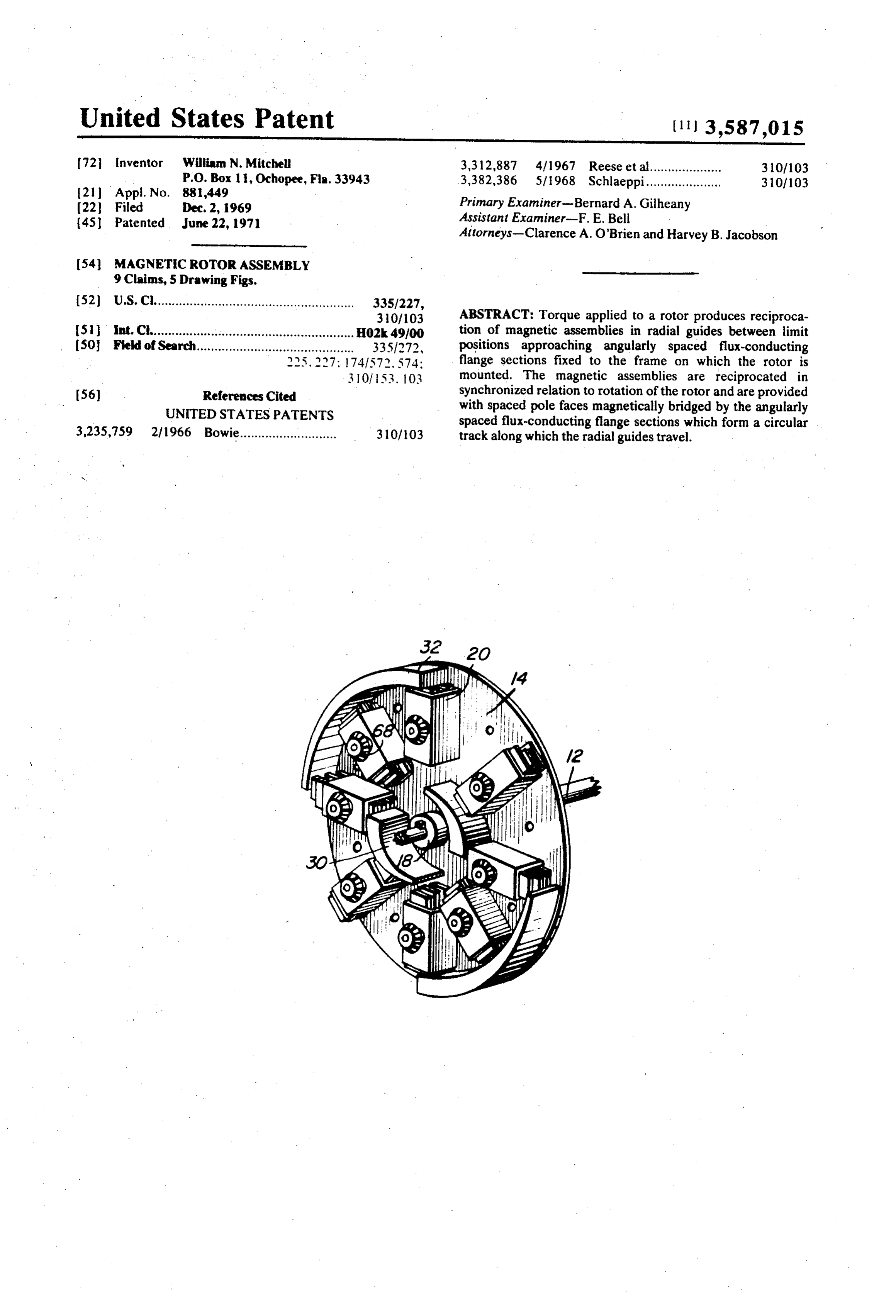
(52) U.S. Cl........................................................ 335/227, 310/103 ABSTRACT: Torque applied to a rotor produces reciproca (51 int.Ch........................................................ H02k 49/00 tion of magnetic assemblies in radial guides between limit (50 Field of Search............................................ 3351272, positions approaching angularly spaced flux-conducting 225, 227: 74.1572. S74; flange sections fixed to the frame on which the rotor is 3 O 53 03 mounted. The magnetic assemblies are reciprocated in 56) References Cited synchronized relation to rotation of the rotor and are provided UNITED STATES PATENTS with spaced pole faces magnetically bridged by the angularly spaced flux-conducting flange sections which form a circular 3,235,759 2/1966 Bowie........................... 310/03 track along which the radial guides travel.
Page 2
Drawing sheet — no readable text.
Page 3
Drawing sheet — no readable text.
Page 4
MAGNETIC ROTOR ASSEMBLY
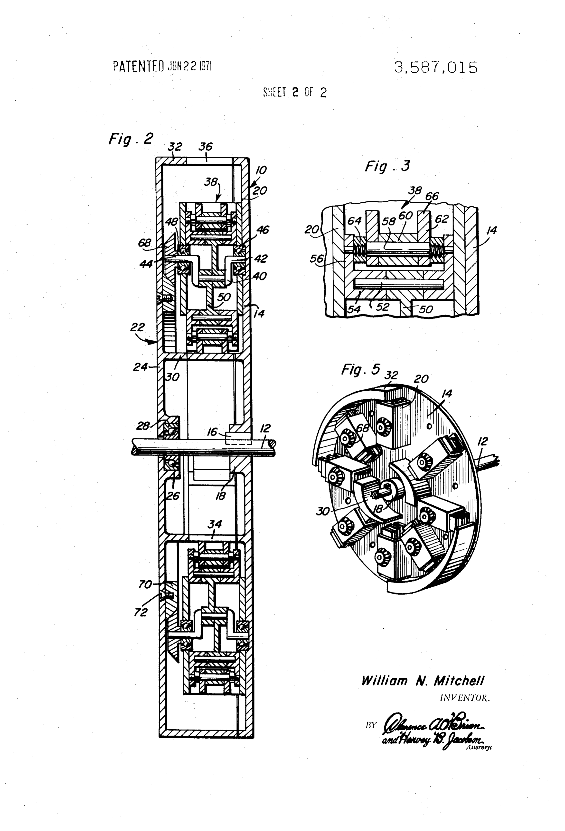
ing rods 50. Each connecting rod is pivotally connected by a wrist pin 52 as more clearly seen in FIG. 3 to tubular forma
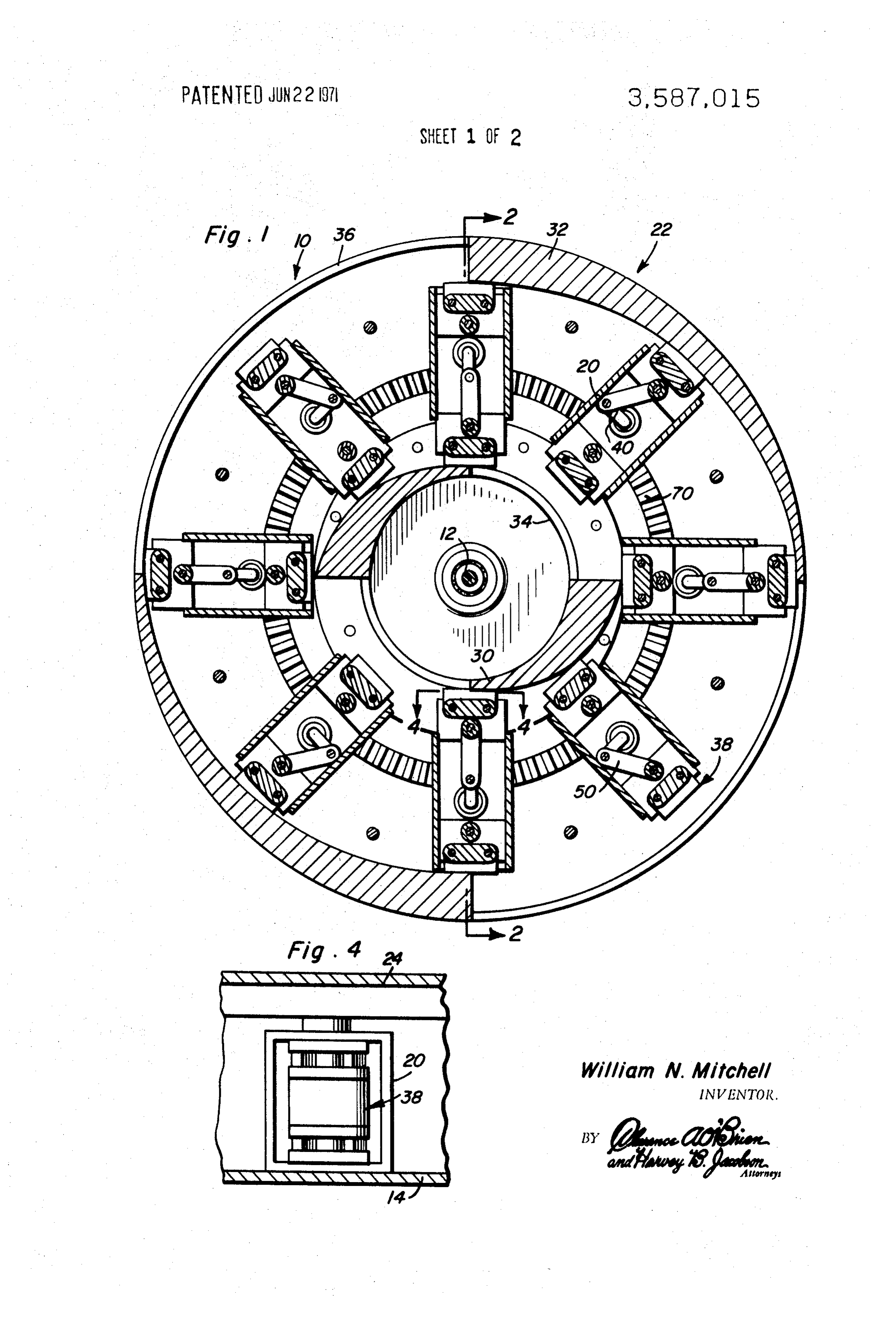
This invention relates to a rotor assembly or magnetic tions 54 projecting from a pair of nonmagnetic slide plates 56, flywheel for absorbing and releasing torque during each in sliding engagement with the opposite walls of the guide tube revolution of the rotor assembly and for other possible 20. A mounting bolt assembly 58 is interconnected between benefits.
the side plates 56 and supports in the illustrated embodiment, in accordance with the present invention, rotation is im an Alnico type of permanent magnet core 60 held clamped parted to a rotor assembly when torque is applied from some between pole face plates 62 of opposite polarity by assembly power source, with the torque loading being varied by mag nuts 64. The pole plates 62 present pole faces 66 of opposite netic attractive forces. Permanent magnet assemblies having 10 polarity adapted to be magnetically bridged by the flux-con spaced pole faces are slidably mounted by radial guides car ducting sections of flange portions 30 and 32 as the magnetic ried by the rotor for reciprocation between limit positions assemblies 38 approach limit positions at the radially inner or bringing the spaced pole faces into proximity with flux gap outer ends of the guide tubes 20.
bridging elements fixed to the rotor frame which are in the The reciprocatory movement of the magnetic assemblies 38 form of radially spaced guides along which the radial guides 15 are synchronized with rotation of the rotor disc 14 so that the travel during rotation of the rotor. The reciprocatory move magnetic assemblies will be in engagement with the guides 30 ment of the magnets are synchronized with the rotation of the and 32 as shown in FIG. 1 and be magnetically attracted rotor by a counterbalanced crank and planetary gear arrange thereto so as to exert accelerating force on the magnetic as ment. Thus, the rotor assembly acts as a magnetic flywheel in 20 semblies tending to rotate the crank in the same direction. regulating the torque applied to a power shaft for example. Toward this end, the crankshaft section 44 projecting from These together with other objects and advantages which will each of the guide tubes 20, is connected to a planet bevel gear become subsequently apparent reside in the details of con 68. The planet bevel gears 68 are in constant mesh with a struction and operation as more fully hereinafter described reaction bevel gear 70 fixed to the frame disc 24 by fasteners and claimed, reference being had to the accompanying 25 72. Accordingly, as the rotor disc 14 is rotated about the axis drawings forming a part hereof, wherein like numerals refer to of shaft 12, the planet bevel pinions 68 are rotated to impart like parts throughout, and in which: synchronized reciprocation to the magnetic assemblies 38 FIG. 1 is a front sectional view through a rotor assembly through the crank and pitman connection between the planet constructed in accordance with the present invention. bevel pinions and the magnetic assemblies within each guide FIG. 2 is a side sectional view taken substantially through a 30 tube. It will be apparent therefore, that as each magnetic as plane indicated by section line 2-2 in FIG. 1. sembly is approaching either the radially outer or radially FIG. 3 is an enlarged partial sectional view of a portion of inner limit position, it experiences an attractive force because the rotor assembly shown in FIG. 2. of the magnetic coaction with the radially inner or outer FIG. 4 is an enlarged partial sectional view taken substan guides.
tially through a plane indicated by section line 4-4 in FIG.1. 35 The foregoing is considered as illustrative only of the princi FIG. 5 is a perspective view showing the rotor assembly dis ples of the invention. Further, since numerous modifications assembled from its associated frame structure. and changes will readily occur to those skilled in the art, it is Referring now to the drawings in detail, and in particular to not desired to limit the invention to the exact construction and FIGS. 1, 2 and 5, the rotor assembly generally denoted by operation shown and described, and accordingly all suitable modifications and equivalents may be resorted to, falling reference numeral 10 is associated with any suitable power 40 within shaft such as the shaft 12 to which a rotor disc 14 is connected the scope of the invention. by the spline 16 extending through the radially inner hub por What I claim as new is as follows: tion 18 of the rotor disc. The rotor disc fixedly mounts a plu 1. A magnetic torque regulating device comprising a frame rality of radial guide tubes 20. The rotor disc 14 and the guide ofhaving radially inner and outer guides, said guides being made tubes 20 fixed thereto are made of a nonmagnetic material or low magnetic reluctance material, a rotor rotatably one having a relatively high magnetic reluctance property. mounted by the frame, radial guide means mounted by the Further, while any desired number of guide tubes 20 may be rotor between the inner and outer guides, magnetic flux emitting means movably mounted by the guide means for utilized in accordance with the present invention, eight of movement such guide tubes are illustrated in the disclosed embodiment 50 inner and outer between limit positions alternately engaging said in equal angular spaced relationship to each other. guides, and drive means connected to the flux The rotor disc 14 and the power shaft 12 to which it is con emitting means for synchronizing rotation of the rotor with nected, are supported in any suitable manner for rotation said movement of the flux-emitting means between said limit about the longitudinal axis of the shaft 12 and in concentric positions.
2. The combination of claim 1 wherein said magnetic flux relation to an associated frame structure generally denoted by 55 emitting means includes magnets slidably mounted within the reference numeral 22 in FIGS. 1 and 2. The frame structure 22 includes a disc portion 24 having a hub 26 which mounts a callyguide means having spaced pole faces adapted to be magneti ball bearing assembly 28 journaling the power shaft 12. Ex bridged by the guides in engagement therewith.
tending axially from the frame, disc 24, are radially inner cludes crankThe combination of claim 2, wherein said drive means in guides 30 and radially outer guides 32. These guides are made 60 and connectedmeans to rotatably mounted by the guide means the flux-emitting means, a reaction gear of a material having a relatively low magnetic reluctance pro member fixedly mounted on the frame, and planet pinion perty. Further, the guides are angularly spaced by gaps 34 and means connected to the crank 36 for alternate engagement with radially inner and outer end gagement with the reaction gearmeans in constant meshing en member.
portions of the guide tubes 20. In the illustrated embodiment, 4. The combination of claim 3 wherein said guides are angu there are two radially inner guides 30 and two radially outer 65 larly spaced apart by nonmagnetic gaps. guides 32 that alternately extend by 90 degrees about the rota 5. The combination of claim 1 wherein said drive means in tional axis of the shaft 12.
Slidably mounted within each of the guide tubes 20, are a and cludes crank means rotatably mounted by the guide means pair of magnetic assemblies generally referred to by reference member connected to the flux-emitting means, a reaction gear numeral 38. The two magnetic assemblies 38 in each guide 70 means connected fixedly mounted on the frame, and planet pinion tube counterbalance each other with respect to a crank 40 gagement with thetoreaction the crank means in constant meshing en gear member.
having a crankshaft sections 42 and 44 rotatably mounted 6. The combination of claim.5 wherein said guides are angu within bearing assemblies 46 and 48 in opposite sidewalls of larly spaced apart by nonmagnetic gaps. the guide tube 20. The magnetic assemblies 38 are connected 7. The combination of claim 1 wherein said guides are angu in 180° relationship to each other to the crank 40 by connect- 75 larly spaced apart by nonmagnetic gaps.
Page 5
8. A magnetic torque regulating device comprising a frame drive means connected to the flux-emitting means for having a guide assembly made of low magnetic reluctance synchronizing rotation of the rotor with said movement of the material, a rotor rotatably mounted by the frame, radial guide flux-emitting means between said limit positions. means mounted by the rotor for movement through the guide 9. The combination of claim 8 wherein said guide assembly. assembly, magnetic flux-emitting means movably mounted by 5 is provided with angular spaced flux gaps therein. the guide means for movement between limit positions, and
Provenance
- Collection
- Cited prior art
- Original PDF
- patentimages.storage.googleapis.com →
- Filed
- 1969-12-02
- Pages
- 5
- Method
- pdftotext (the PDF's own text layer) + pdftoppm 300dpi page scans
- Source
- Google Patents bibliographic record
- Granted
- 1971-06-22
- Inventors
- William N Mitchell
- Transcribed from
- patentimages.storage.googleapis.com →