patent · US4752706
Rolling magnetic friction electricity generator
21 June 1988
Page 1 — bibliographic record
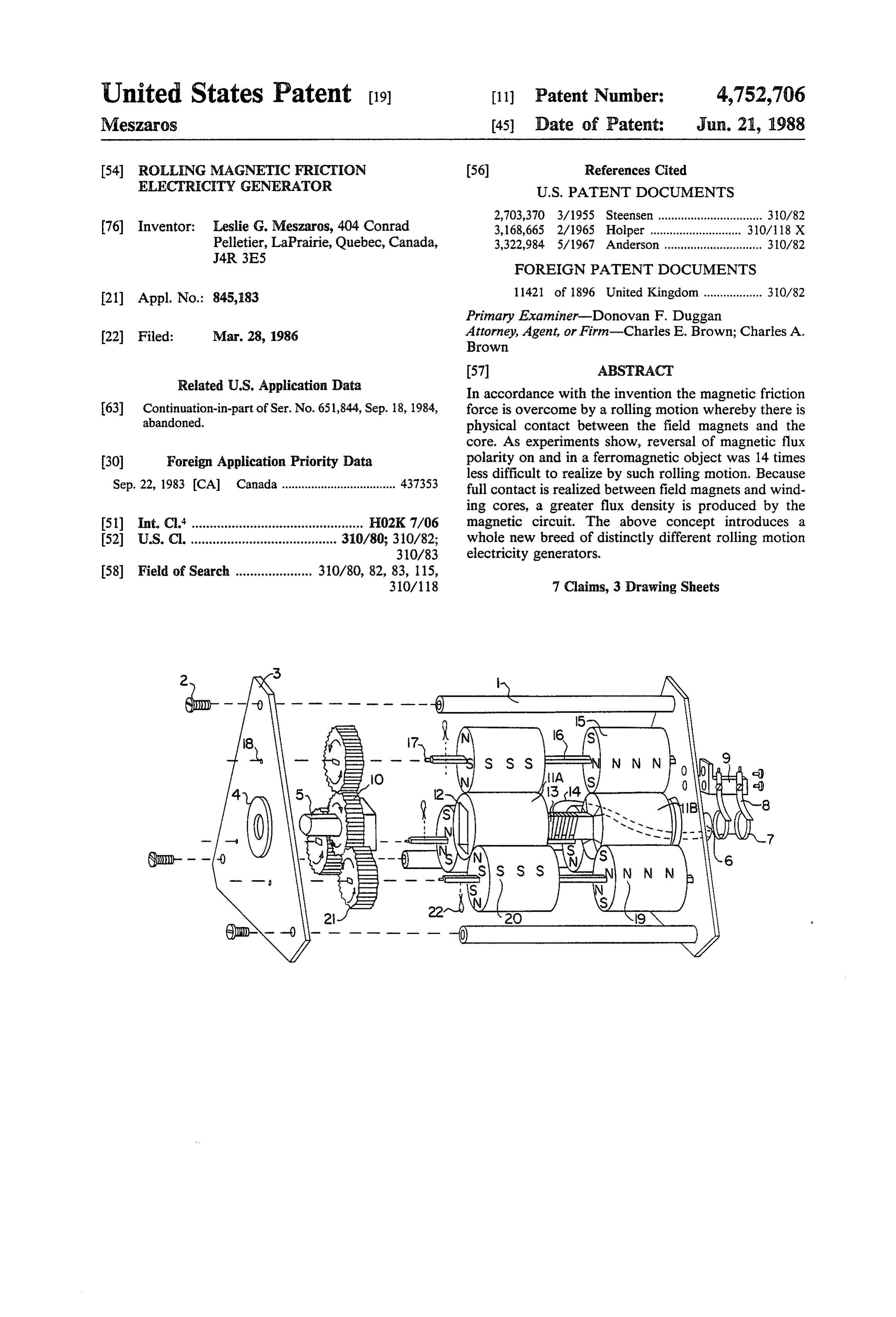
United States Patent (19) 11 Patent Number: 4,752,706 Meszaros (45) Date of Patent: Jun. 21, 1988 (54) ROLLING MAGNETIC FRICTION 56) References Cited ELECTRECTY GENERATOR U.S. PATENT DOCUMENTS 2,703,370 3/1955 Steensen ................................ 3.0/82 76 Inventor: Leslie G. Meszaros, 404 Conrad 3,168,665 2/1965 Holper ...... ... 310/118 X Pelletier, LaPrairie, Quebec, Canada, 3,322,984 5/1967 Anderson .............................. 310/82
FOREIGN PATENT DOCUMENTS
21 Appl. No.: 845,183 11421 of 1896 United Kingdom .................. 310/82 Primary Examiner-Donovan F. Duggan 22 Filed: Mar. 28, 1986 Attorney, Agent, or Firm-Charles E. Brown; Charles A. Brown
Related U.S. Application Data In accordance with the invention the magnetic friction 63 Continuation-in-part of Ser. No. 651,844, Sep. 18, 1984, force is overcome by a rolling motion whereby there is abandoned. physical contact between the field magnets and the core. As experiments show, reversal of magnetic flux 30 Foreign Application Priority Data polarity on and in a ferromagnetic object was 14 times Sep. 22, 1983 (CA) Canada ................................... 437353 less difficult to realize by such rolling motion. Because full contact is realized between field magnets and wind ing cores, a greater flux density is produced by the 51) Int. Cl* ............................................... HO2K7/06 magnetic circuit. The above concept introduces a 52 U.S. C. ........................................ 310/80; 310/82; whole new breed of distinctly different rolling motion 310/83 electricity generators.
58) Field of Search ..................... 310/80, 82, 83, 115,
Page 2
Drawing sheet — no readable text.
Page 3
Drawing sheet — no readable text.
Page 4
Drawing sheet — no readable text.
Page 5
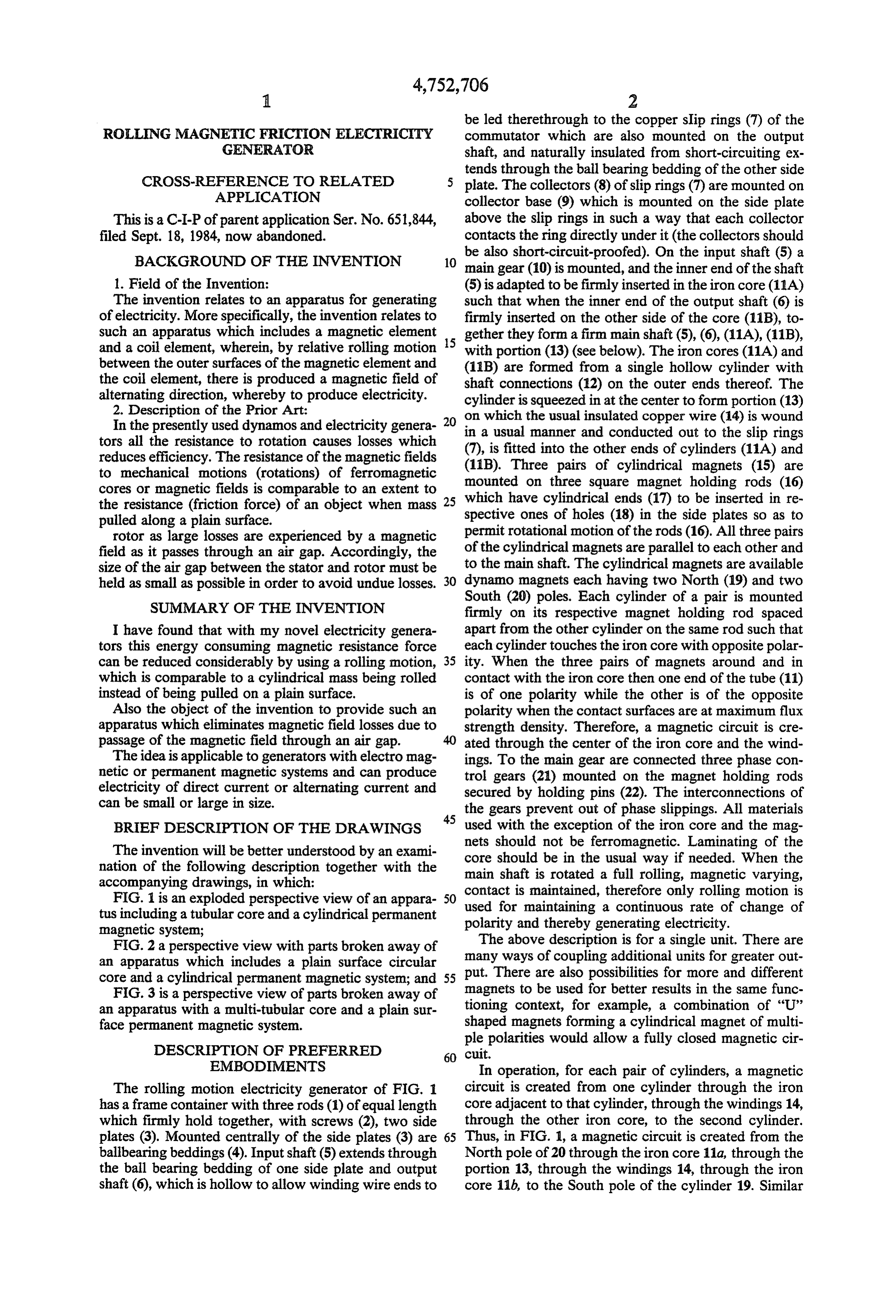
be led therethrough to the copper slip rings (7) of the
ROLLING MAGNETIC FRCTION ELECTRICTY commutator which are also mounted on the output GENERATOR shaft, and naturally insulated from short-circuiting ex tends through the ball bearing bedding of the other side
CROSS-REFERENCE TO RELATED 5 plate. The collectors (8) of slip rings (7) are mounted on APPLICATION collector base (9) which is mounted on the side plate This is a C-I-P of parent application Ser. No. 651,844, above the slip rings in such a way that each collector filed Sept. 18, 1984, now abandoned. contacts the ring directly under it (the collectors should
be also short-circuit-proofed). On the input shaft (5) a main gear (10) is mounted, and the inner end of the shaft 1. Field of the Invention: (5) is adapted to be firmly inserted in the iron core (11A) The invention relates to an apparatus for generating such that when the inner end of the output shaft (6) is of electricity. More specifically, the invention relates tofirmly inserted on the other side of the core (11B), to such an apparatus which includes a magnetic element gether they form a firm main shaft (5), (6), (11A), (11B), and a coil element, wherein, by relative rolling motion with portion (13) (see below). The iron cores (11A) and between the outer surfaces of the magnetic element and (11B) are formed from a single hollow cylinder with the coil element, there is produced a magnetic field of shaft connections (12) on the outer ends thereof. The alternating direction, whereby to produce electricity. cylinder is squeezed in at the center to form portion (13) 2. Description of the Prior Art:
In the presently used dynamos and electricity genera- 20 on
which the usual insulated copper wire (14) is wound usual manner and conducted out to the slip rings tors all the resistance to rotation causes losses which reduces efficiency. The resistance of the magnetic fields (11B). fitted (7), is into the other ends of cylinders (11A) and
Three pairs of cylindrical magnets (15) are to mechanical motions (rotations) of ferromagnetic mounted on three square magnet holding rods (16) cores or magnetic fields is comparable to an extent to which the resistance (friction force) of an object when mass spectivehave 25 cylindrical ends (17) to be inserted in re ones of holes (18) in the side plates so as to pulled along a plain surface.
rotor as large losses are experienced by a magnetic permit rotational motion of the rods (16). All three pairs field as it passes through an air gap. Accordingly, the of the cylindrical magnets are parallel to each other and size of the air gap between the stator and rotor must be to the main shaft. The cylindrical magnets are available held as small as possible in order to avoid undue losses. 30 dynamo magnets each having two North (19) and two
SUMMARY OF THE INVENTION
South (20) poles. Each cylinder of a pair is mounted firmly on its respective magnet holding rod spaced
I have found that with my novel electricity genera apart from the other cylinder on the same rod such that tors this energy consuming magnetic resistance force each cylinder touches the iron core with opposite polar can be reduced considerably by using a rolling motion, 35 ity. When the three pairs of magnets around and in which is comparable to a cylindrical mass being rolled contact with the iron core then one end of the tube (11) instead of being pulled on a plain surface. is of one polarity while the other is of the opposite Also the object of the invention to provide such an polarity when the contact surfaces are at maximum flux apparatus which eliminates magnetic field losses due to strength density. Therefore, a magnetic circuit is cre passage of the magnetic field through an air gap. ated through the center of the iron core and the wind The idea is applicable to generators with electromag ings. To the main gear are connected three phase con netic or permanent magnetic systems and can produce trol gears (21) mounted on the magnet holding rods electricity of direct current or alternating current and secured by holding pins (22). The interconnections of can be small or large in size. the gears prevent out of phase slippings. All materials
BRIEF DESCRIPTION OF THE DRAWINGS used with the exception of the iron core and the mag nets should not be ferromagnetic. Laminating of the
The invention will be better understood by an exami core should be in the usual way if needed. When the nation of the following description together with the main shaft is rotated a full rolling, magnetic varying, accompanying drawings, in which:
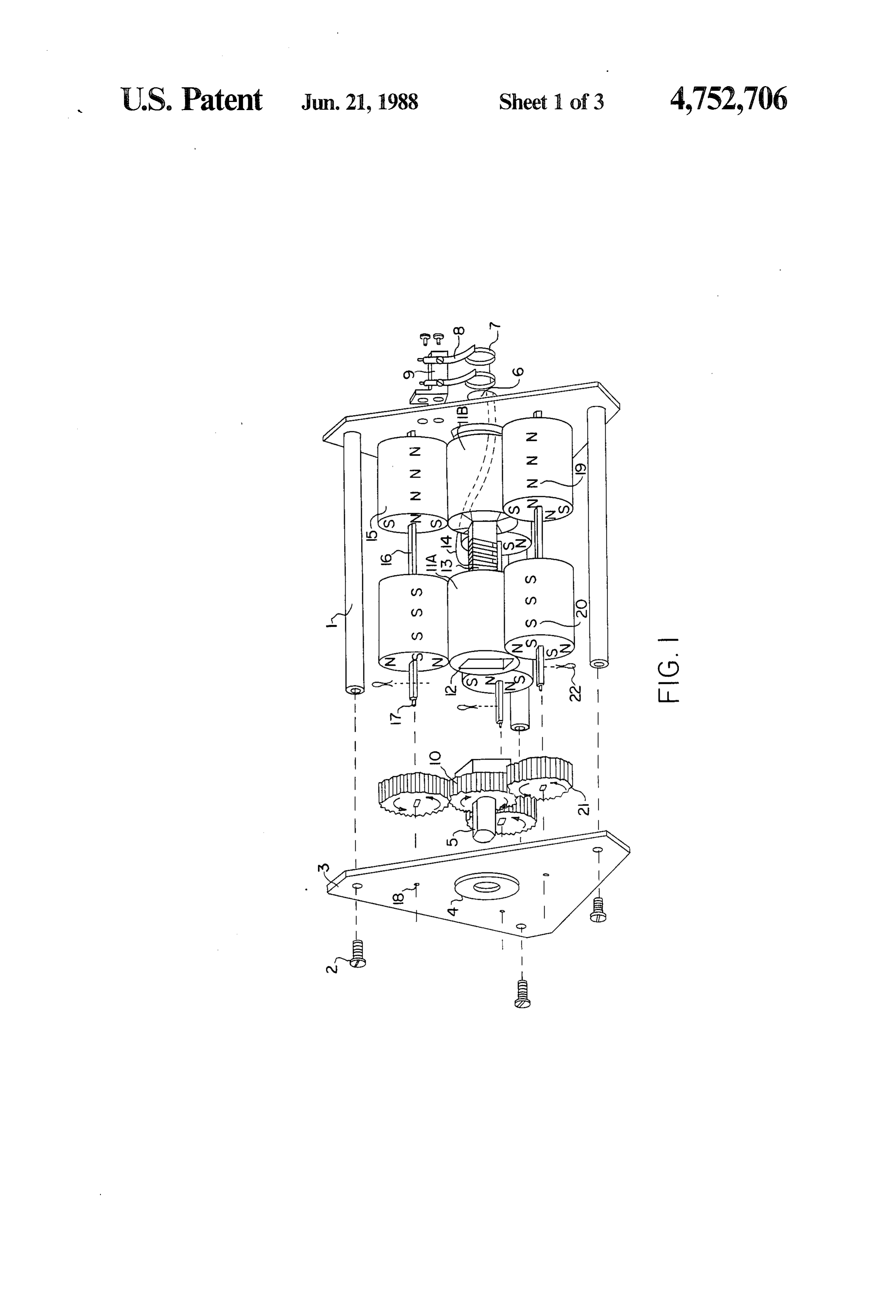
FIG. 1 is an exploded perspective view of an appara SO contact used for is maintained, therefore only rolling motion is maintaining a continuous rate of change of tus including a tubular core and a cylindrical permanent polarity and thereby generating electricity. magnetic system;
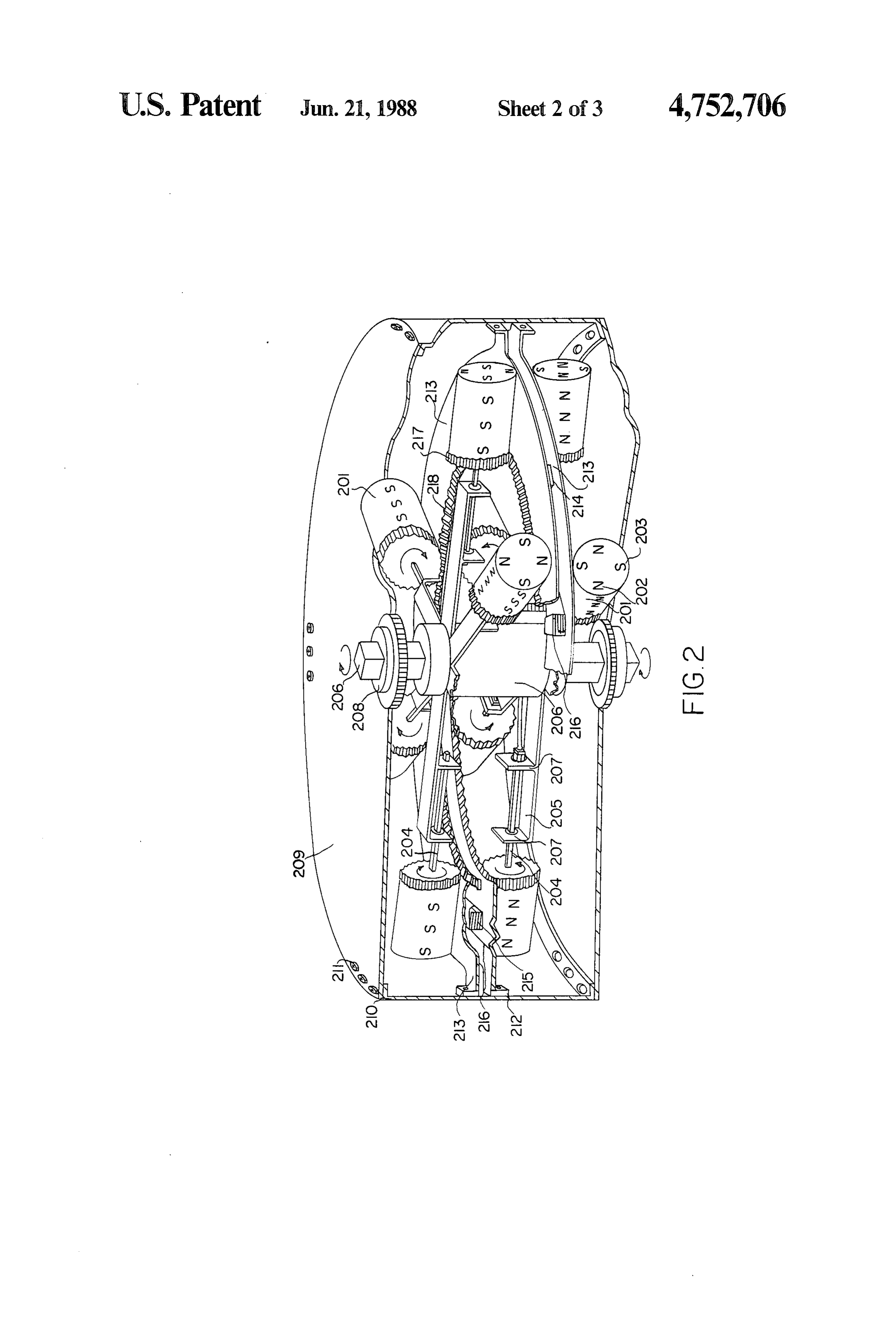
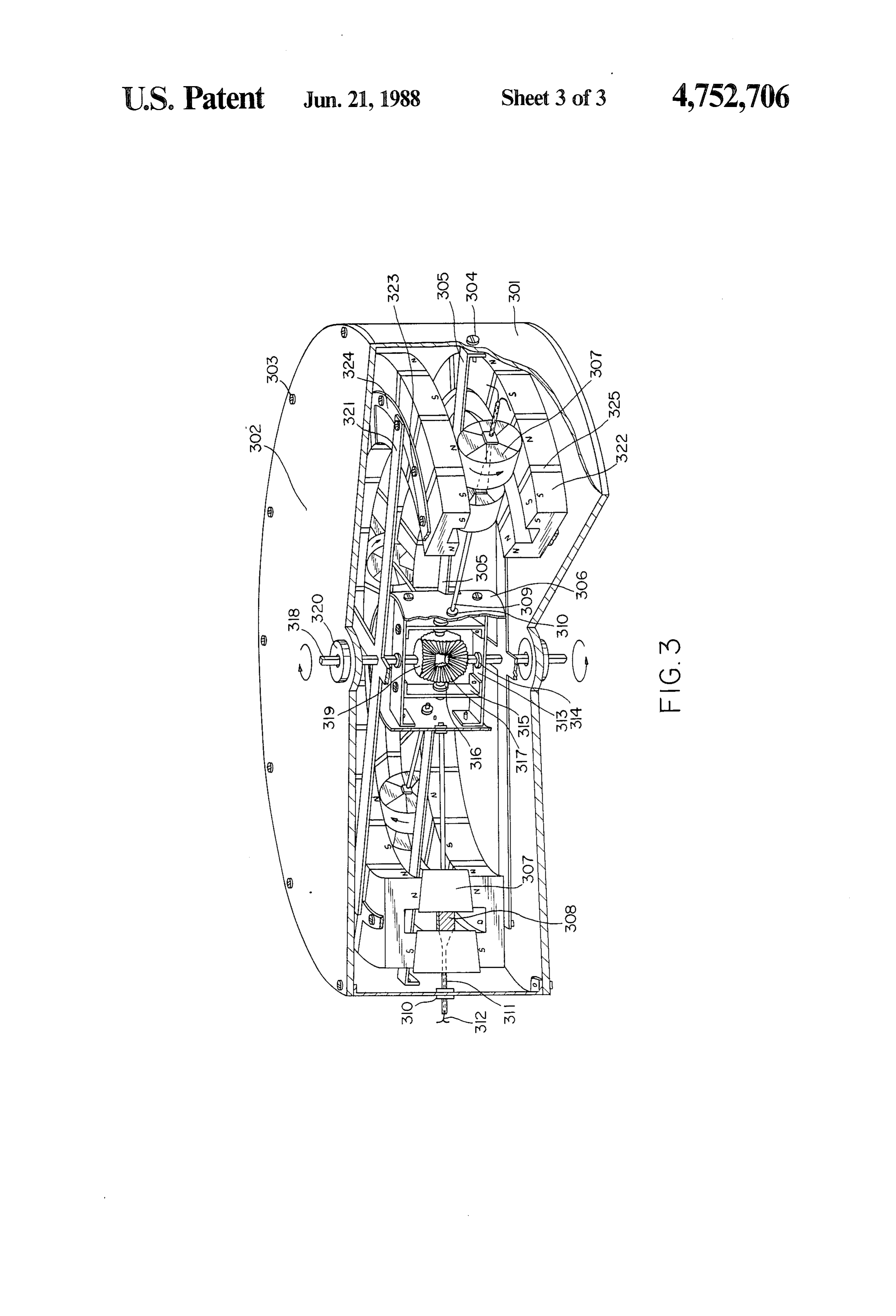
FIG. 2 a perspective view with parts broken away of The above description is for a single unit. There are an apparatus which includes a plain surface circular many ways of coupling additional units for greater out core and a cylindrical permanent magnetic system; and 55 put. There are also possibilities for more and different FIG. 3 is a perspective view of parts broken away of magnets to be used for better results in the same func an apparatus with a multi-tubular core and a plain sur tioning context, for example, a combination of “U” shaped magnets forming a cylindrical magnet of multi face permanent magnetic system.
ple polarities would allow a fully closed magnetic cir
EMBODEMENTS In operation, for each pair of cylinders, a magnetic The rolling motion electricity generator of FIG. 1 circuit is created from one cylinder through the iron has a frame container with three rods (1) of equal length core adjacent to that cylinder, through the windings 14, which firmly hold together, with screws (2), two side through the other iron core, to the second cylinder. plates (3). Mounted centrally of the side plates (3) are 65 Thus, in FIG. 1, a magnetic circuit is created from the ballbearing beddings (4). Input shaft (5) extends through North pole of 20 through the iron core 11a, through the the ball bearing bedding of one side plate and output portion 13, through the windings 14, through the iron shaft (6), which is hollow to allow winding wire ends to core 11b, to the South pole of the cylinder 19. Similar
Page 6
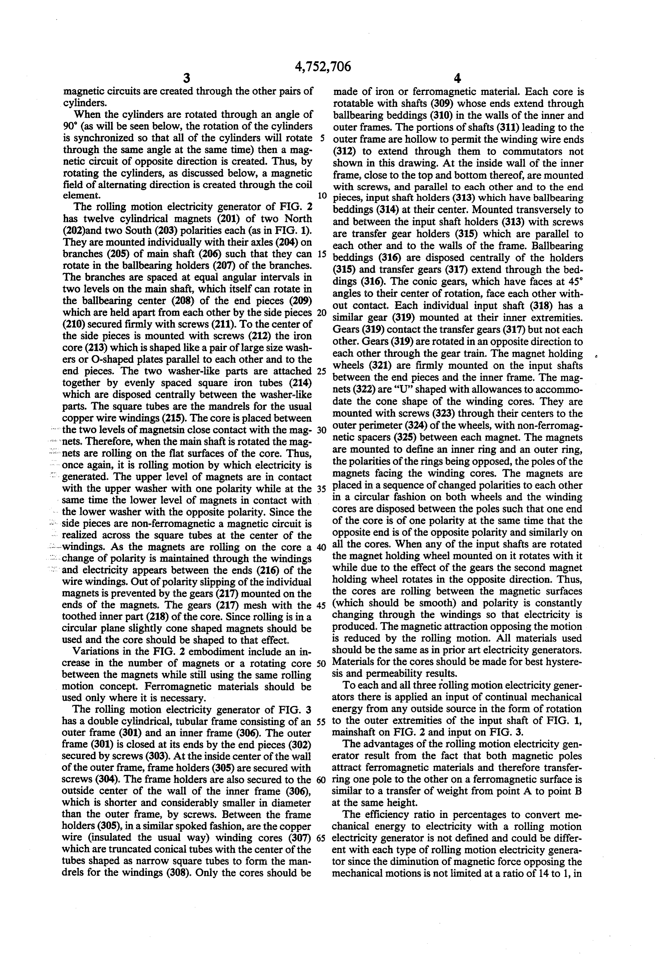
magnetic circuits are created through the other pairs of made of iron or ferromagnetic material. Each core is cylinders. rotatable with shafts (309) whose ends extend through When the cylinders are rotated through an angle of ballbearing beddings (310) in the walls of the inner and 90' (as will be seen below, the rotation of the cylinders outer frames. The portions of shafts (311) leading to the is synchronized so that all of the cylinders will rotate 5 outer frame are hollow to permit the winding wire ends through the same angle at the same time) then a mag (312) to extend through them to commutators not netic circuit of opposite direction is created. Thus, by shown in this drawing. At the inside wall of the inner rotating the cylinders, as discussed below, a magnetic frame, close to the top and bottom thereof, are mounted field of alternating direction is created through the coil with screws, and parallel to each other and to the end element. O pieces, input shaft holders (313) which have ballbearing The rolling motion electricity generator of FIG. 2 beddings (314) at their center, Mounted transversely to has twelve cylindrical magnets (201) of two North and between the input shaft holders (313) with screws (202)and two South (203) polarities each (as in FIG. 1). are transfer gear holders (315) which are parallel to They are mounted individually with their axles (204) on each other and to the walls of the frame. Ballbearing branches (205) of main shaft (206) such that they can 15 beddings (316) are disposed centrally of the holders rotate in the ballbearing holders (207) of the branches.
The branches are spaced at equal angular intervals in (315) and transfer gears (317) extend through the bed two levels on the main shaft, which itself can rotate in angles(316).
dings
The conic gears, which have faces at 45° their center of rotation, face each other with the ballbearing center (208) of the end pieces (209) out contact. Each individual input shaft (318) has a which are held apart from each other by the side pieces 20 similar gear (319) mounted at their inner extremities. (210) secured firmly with screws (211). To the center of the side pieces is mounted with screws (212) the iron Gears (319) contact the transfer gears (317) but not each core (213) which is shaped like a pair of large size wash other. Gears (319) are rotated in an opposite direction to ers or O-shaped plates parallel to each other and to the each other through the gear train. The magnet holding end pieces. The two washer-like parts are attached 25 wheels (321) are firmly mounted on the input shafts together by evenly spaced square iron tubes (214) between the end pieces and the inner frame. The mag which are disposed centrally between the washer-like nets (322) are “U” shaped with allowances to accommo date the cone shape of the winding cores. They are parts. The square tubes are the mandrels for the usual mounted with screws (323) through their centers to the copper wire windings (215). The core is placed between outer perimeter (324) of the wheels, with non-ferromag the two levels of magnetsin close contact with the mag- 30 netic spacers (325) between each magnet. The magnets * nets. Therefore, when the main shaft is rotated the mag are mounted to define nets are rolling on the flat surfaces of the core. Thus, the polarities of the ringsanbeing inner ring and an outer ring, opposed, the poles of the once again, it is rolling motion by which electricity is generated. The upper level of magnets are in contact placed magnets facing the winding cores. The magnets are with the upper washer with one polarity while at the 35 in a sequence of changed polarities to each other same time the lower level of magnets in contact with in a circular fashion on both wheels and the winding - the lower washer with the opposite polarity. Since the cores are disposed between the poles such that one end - side pieces are non-ferromagnetic a magnetic circuit is of the core is of one polarity at the same time that the - realized across the square tubes at the center of the opposite end is of the opposite polarity and similarly on --windings. As the magnets are rolling on the core a 40 all the cores. When any of the input shafts are rotated ... change of polarity is maintained through the windings the magnet holding wheel mounted on it rotates with it ... and electricity appears between the ends (216) of the while due to the effect of the gears the second magnet wire windings. Out of polarity slipping of the individual holding wheel rotates in the opposite direction. Thus, magnets is prevented by the gears (217) mounted on the the cores are rolling between the magnetic surfaces ends of the magnets. The gears (217) mesh with the 45 (which should be smooth) and polarity is constantly toothed inner part (218) of the core. Since rolling is in a changing through the windings so that electricity is circular plane slightly cone shaped magnets should be produced. The magnetic attraction opposing the motion used and the core should be shaped to that effect. is reduced by the rolling motion. All materials used Variations in the FIG. 2 embodiment include an in should be the same as in prior art electricity generators. crease in the number of magnets or a rotating core 50 Materials for the cores should be made for best hystere between the magnets while still using the same rolling sis and permeability results.
motion concept. Ferromagnetic materials should be To each and all three folling motion electricity gener used only where it is necessary. ators there is applied an input of continual mechanical The rolling motion electricity generator of FIG. 3 energy from any outside source in the form of rotation has a double cylindrical, tubular frame consisting of an 55 to the outer extremities of the input shaft of FIG. 1, outer frame (301) and an inner frame (306). The outer mainshaft on FIG. 2 and input on FIG. 3. frame (301) is closed at its ends by the end pieces (302) The advantages of the rolling motion electricity gen secured by screws (303). At the inside center of the wall erator result from the fact that both magnetic poles of the outer frame, frame holders (305) are secured with attract ferromagnetic materials and therefore transfer screws (304). The frame holders are also secured to the 60 ring one pole to the other on a ferromagnetic surface is outside center of the wall of the inner frame (306), similar to a transfer of weight from point A to point B which is shorter and considerably smaller in diameter at the same height.
than the outer frame, by screws. Between the frame The efficiency ratio in percentages to convert me holders (305), in a similar spoked fashion, are the copper chanical energy to electricity with a rolling motion wire (insulated the usual way) winding cores (307) 65 electricity generator is not defined and could be differ which are truncated conical tubes with the center of the ent with each type of rolling motion electricity genera tubes shaped as narrow square tubes to form the man tor since the diminution of magnetic force opposing the drels for the windings (308). Only the cores should be mechanical motions is not limited at a ratio of 14 to 1, in
Page 7
a way as diminution of kinetic or static friction by roll 3. An apparatus as defined in claim 2 wherein said ing friction is dependent on many factors. magnetic means comprises three arrangements; Although particular embodiments have been de said arrangements being spaced at equal angular in scribed, this was for the purpose of illustrating, but not tervals around said pair of cylinders. limiting the invention. Various modifications, which 5 4. An apparatus as defined in claim 3 and further come readily to the mind of one skilled in the art, are including gear means mounted at a common end of each within the scope of the invention as defined in the ap of the axles of said three arrangements; pended claims. shaft means connectable at one end thereof to me I claim: chanical means for rotating said shaft means and 1. A generator for producing electricity by rolling 10 connected at the other end thereof to said pair of motion, comprising: cylinders such that, when said shaft means is ro a magnetic means to produce at least two magnetic tated, said pair of cylinders will rotate with said poles, said magnetic means comprising a set of at shaft means;
least two like, spaced structures, each of said struc 15 a gear member, meshing with said gear means tures having an outer surface, and means for fixedly mounted on said shaft means, whereby, when said connecting said structures relative to each other; shaft means is rotated, said gear member rotates b. at least one winding core means having a set of at thereby causing said gear means and, thereby, said least two like, spaced structures comprising a con arrangements, to rotate such that said cylindrical ductive material, each of said structures having an magnets roll along the surfaces of said pair of cylin outer surface, a mandrel disposed between said ders; and structures to fixedly connect said structures rela wire ends extending from said coil to a slip ring ar tive to each other, said mandrel having a plurality rangement;
of coil turns wound thereon; whereby to collect electricity generated by said gen c. container means for maintaining the outer surface 25 erator.
of one of said structures of said magnetic means in 5. An apparatus as defined in claim 1 wherein: physical contact with the outer surface of one of 1 said set of structures of said winding core means said structures of said winding core means, and the comprises:
outer surface of the other one of said structures of a. a pair of O-shaped plates disposed in concentric, said magnetic means in physical contact with the 30 spaced arrangement parallel to each other; outer surface of the other one of said structures of b. a plurality of winding mandrels disposed in the said winding core means such that the outer sur spaces between said plates at equal angular inter faces of one of said sets is rollable on the outer vals;
surfaces of the other one of said sets; 2 said set of structures of said magnetic means com whereby, to define a magnetic circuit from said one 35 prises:
of said structures of said magnetic means, through a, a first plurality of magnets, in the shape of trun said one of said structures of said winding core cated cones, mounted for rolling contact on the means, through said plurality of coil turns, through top surface of the top plate at equal angular inter said other one of said structures of said winding vals therearound;
core means, through said other one of said struc 40 b. a second plurality of magnets, in the shape of tures of said magnetic means, and back to said one truncated cones, mounted for rolling contact on of said structures of said magnetic means; the bottom surface of the bottom plate at equal whereupon, to produce electricity in said plurality of angular intervals therearound; coil turns on the application of mechanical energy c. said first plurality being equal to said second to cause rolling motion of the external surfaces of 45 plurality;
said one of said sets on the external surfaces of the d. respective ones of the magnets of the first plural other one of said sets to thereby produce a continu ity being disposed adjacent respective ones of ous reversal of magnetic flux direction in said the magnets of the second plurality such that winding core means. facing surfaces of the respective cylindrical mag 2. An apparatus as defined in claim 1 wherein said set 50 nets are of opposite polarities; of structures of said magnetic means comprises an ar 3 an input shaft for receiving rotary motion; rangement comprising at least one pair of cylindrical 4 means for transferring said input rotary motion to magnets of multiple polarities on the external rollable said magnetic means; and surfaces of said cylindrical magnets, said means for 5 meshing gears to control out of phase slippage be fixing comprising a common axle, said cylindrical mag 55 tween said input shaft and said transmission means. nets being mounted at opposite ends of said common 6. An apparatus as defined in claim 5 wherein said axle such that polarities of either one of said cylindrical input shaft extends centrally through said pair of O magnets are aligned with opposite polarities of the other shaped plates;
one of said magnets; a plurality of arms extending transversely of said said set of structures of said winding core means 60 input shaft and being spaced at equal angular inter comprising a pair of cylinders mounted at opposite vals therearound, said first plurality of arms being ends of said mandrel to form a rollable core and equal to said first plurality of magnets, a separate disposed such that the cylinders are in physical one of said first plurality of arms being associated contact with respective ones of the cylindrical with a separate one of said first plurality of mag magnets and the winding cores adjacent the space 65 nets, and means for connecting each magnet of said between said cylindrical magnets; first plurality of magnets to its associated arm such whereby the surfaces of said cylindrical magnets are that the cylindrical magnets are rotatable relative rollable along the surfaces of said cylinders. to their associated arms;
Page 8
a second plurality of arms extending transversely of b. a second magnetic ring consisting of a second said input shaft and being spaced at equal angular plurality of equal sized magnets which are U intervals therearound, said second plurality of arms shaped in cross-section, each leg of each U being being equal to said second plurality of magnets, a of opposite polarity to the other leg of the same separate one of said second plurality of arms being 5 U, like portions of the magnets being of opposite associated with a separate one of said second plu polarity to like portions of abutting magnets; rality of magnets, and means for connecting each c. said first magnetic ring being disposed in spaced magnet of said second plurality of magnets to its parallel relationship with said second magnetic associated arm of said second plurality such that 10 ring such that the legs of the first magnetic ring the magnets are rotatable relative to their associ face the legs of the second magnetic ring, adja ated arms; cent legs of each ring being of the same polarity; whereby, when said input shaft is rotated, said arms e. non-ferromagnetic spacers being disposed, be and magnets are rotated such that said first plural tween each of the magnets; ity of magnets will roll along the top surface of the 15 2 said set of structures of winding core means come prises:
top O-shaped plate and the second plurality of a. a plurality of rolling elements spaced at equal magnets will roll along the bottom surface or the angular intervals between said rings, each ele bottom O-shaped plate. ment being in the shape of a truncated cone and 7. An apparatus as defined in claim 1 wherein: comprising:
1 said set of structures of said magnetic means con 20 i., a first rolling surface for rolling along the sur prises: faces of the inner legs of the two rings; a. a first magnetic ring consisting of a first plurality ii. a second, spaced, rolling surface for rolling of equal sized magnets which are U-shaped in along the surfaces of the outer legs of the two cross-section, each leg of each U being of oppo rings;
site polarity to the other leg of the same U, like 25 iii. means supporting a winding core between portions of the magnets being of opposite polar said first ands second rolling surfaces. ity to like portions of abutting magnets;
Provenance
- Collection
- Cited prior art
- Original PDF
- patentimages.storage.googleapis.com →
- Filed
- 1986-03-28
- Pages
- 8
- Method
- pdftotext (the PDF's own text layer) + pdftoppm 300dpi page scans
- Source
- Google Patents bibliographic record
- Granted
- 1988-06-21
- Inventors
- Leslie G. Meszaros
- Transcribed from
- patentimages.storage.googleapis.com →