patent · US4289988
Centrifugal mechanism and switch
15 September 1981
Page 1 — bibliographic record
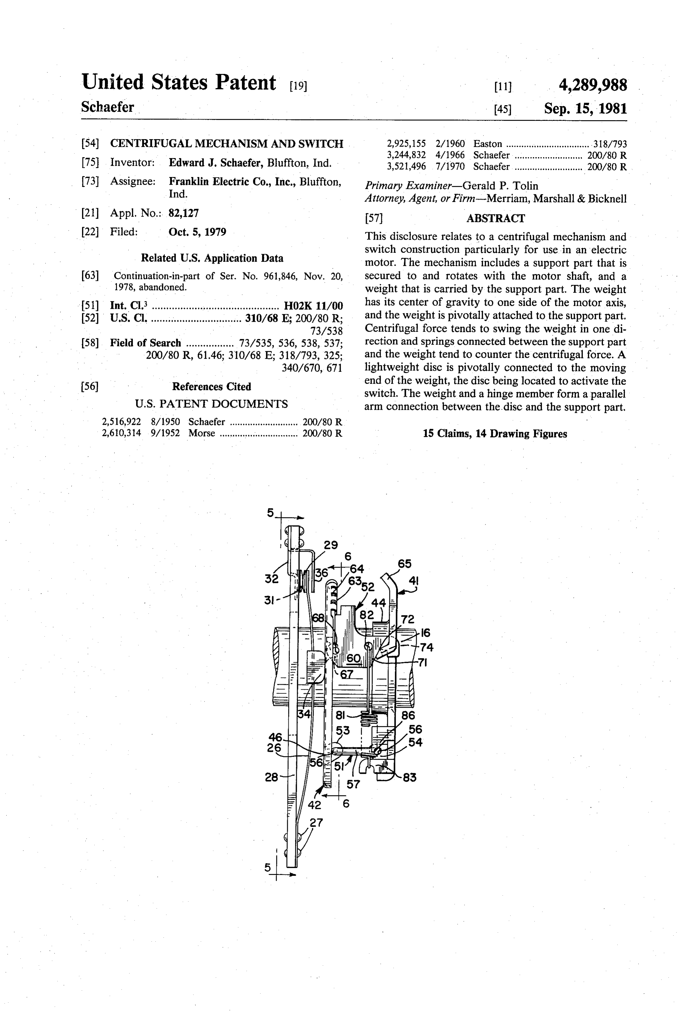
United States Patent (19) 11 4,289.988 Schaefer 45) Sep. 15, 1981 (54 CENTRIFUGAL MECHANISM AND SWITCH 2,925,155 2/1960 Easton ................................. .318/793 75 Inventor: Edward J. Schaefer, Bluffton, Ind. 3,244,832 4/1966 Schaefer ... ..., 200/80 R 3,521,496 7/1970 Schaefer ........................... 200/80 R 73) Assignee: Franklin Electric Co., Inc., Bluffton, Primary Examiner-Gerald P. Tolin Ind. Attorney, Agent, or Firm-Merriam, Marshall & Bicknell 21 Appl. No.: 82,127 (57) ABSTRACT 22 Filed: Oct. 5, 1979 This disclosure relates to a centrifugal mechanism and Related U.S. Application Data switch construction particularly for use in an electric motor. The mechanism includes a support part that is 63 Continuation-in-part of Ser. No. 961,846, Nov. 20, secured to and rotates with the motor shaft, and a 1978, abandoned. weight that is carried by the support part. The weight 51) Int. Cl. ............................................. H02K11/00 has its center of gravity to one side of the motor axis, 52 U.S. Cl. ................................ 310/68 E; 200/80 R; and the weight is pivotally attached to the support part, 73/538 Centrifugal force tends to swing the weight in one di 58) Field of Search ................. 73/535, 536,538, 537; rection and springs connected between the support part 200/80 R, 61.46; 310/68 E; 318/793, 325; and the weight tend to counter the centrifugal force. A 340/670, 671 lightweight disc is pivotally connected to the moving 56) References Cited end of the weight, the disc being located to activate the switch. The weight and a hinge member form a parallel
2,516,922 8/1950 Schaefer ........................... 200/80 R 2,610,314 9/1952 Morse ............................... 200/80 R 15 Claims, 14 Drawing Figures
Page 2
Drawing sheet — no readable text.
Page 3
Drawing sheet — no readable text.
Page 4
Drawing sheet — no readable text.
Page 5
Drawing sheet — no readable text.
Page 6
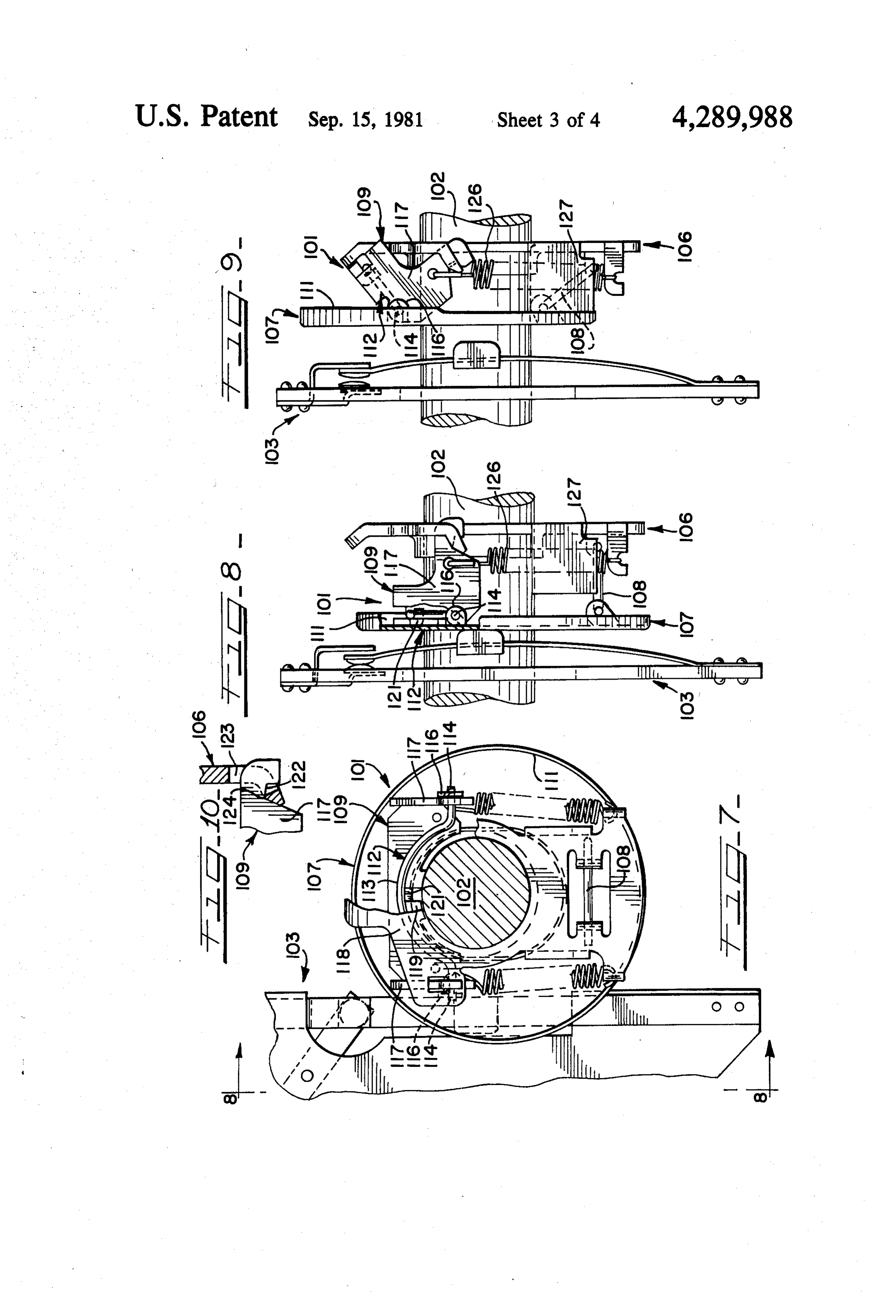
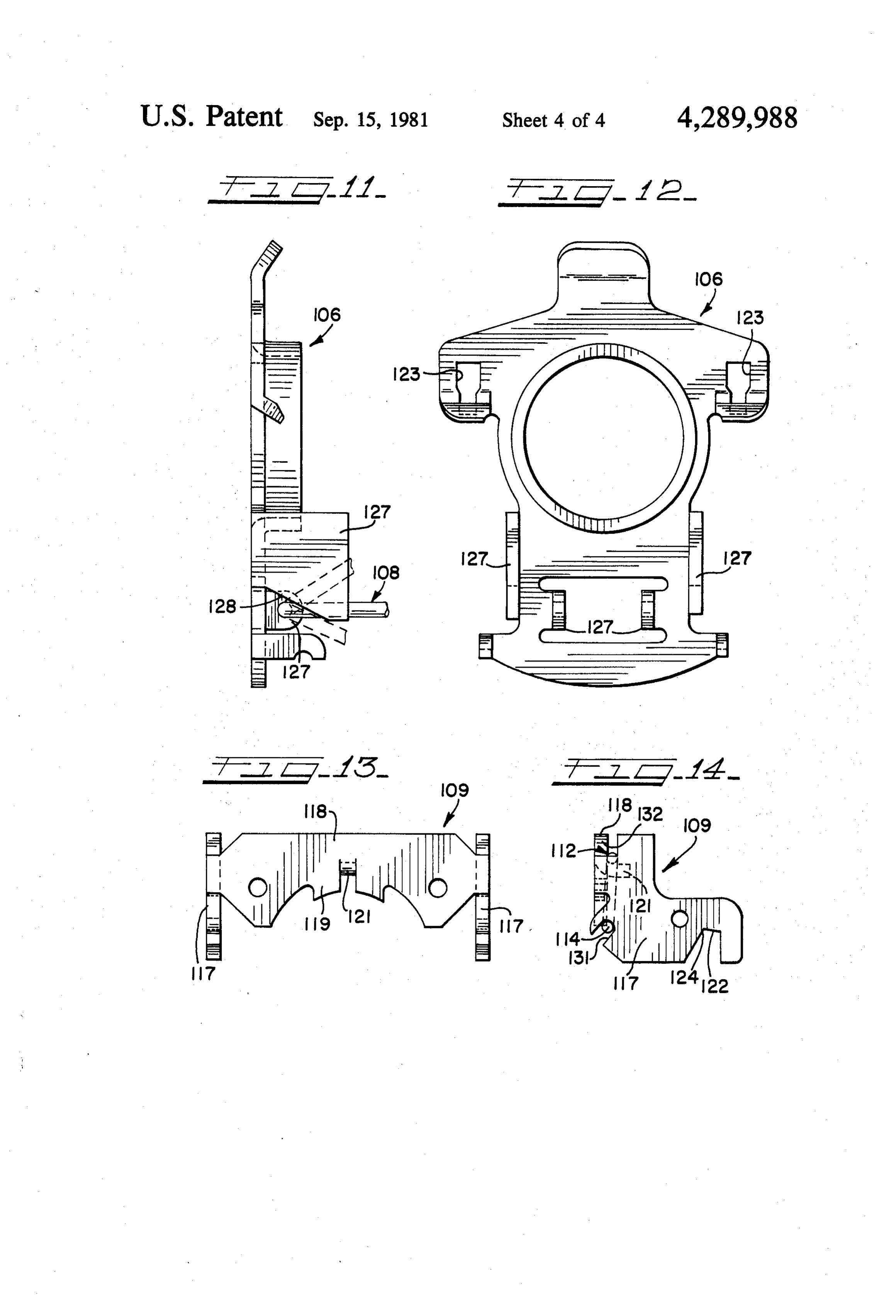
FIG. 10 shows a pivot mounting of the centrifugal
CENTRIFUGAL MECHANISMAND SWITCH mechanism;
FIGS. 11 and 12 are views of one part of the embodi
This patent application is a continuation-in-part appli ment of FIG. 7; and cation based on U.S. application Ser. No. 961,846 filed 5 FIGS. 13 and 14 are views of another part of the Nov. 20, 1978, and now abandoned. embodiment shown in FIG. 7.
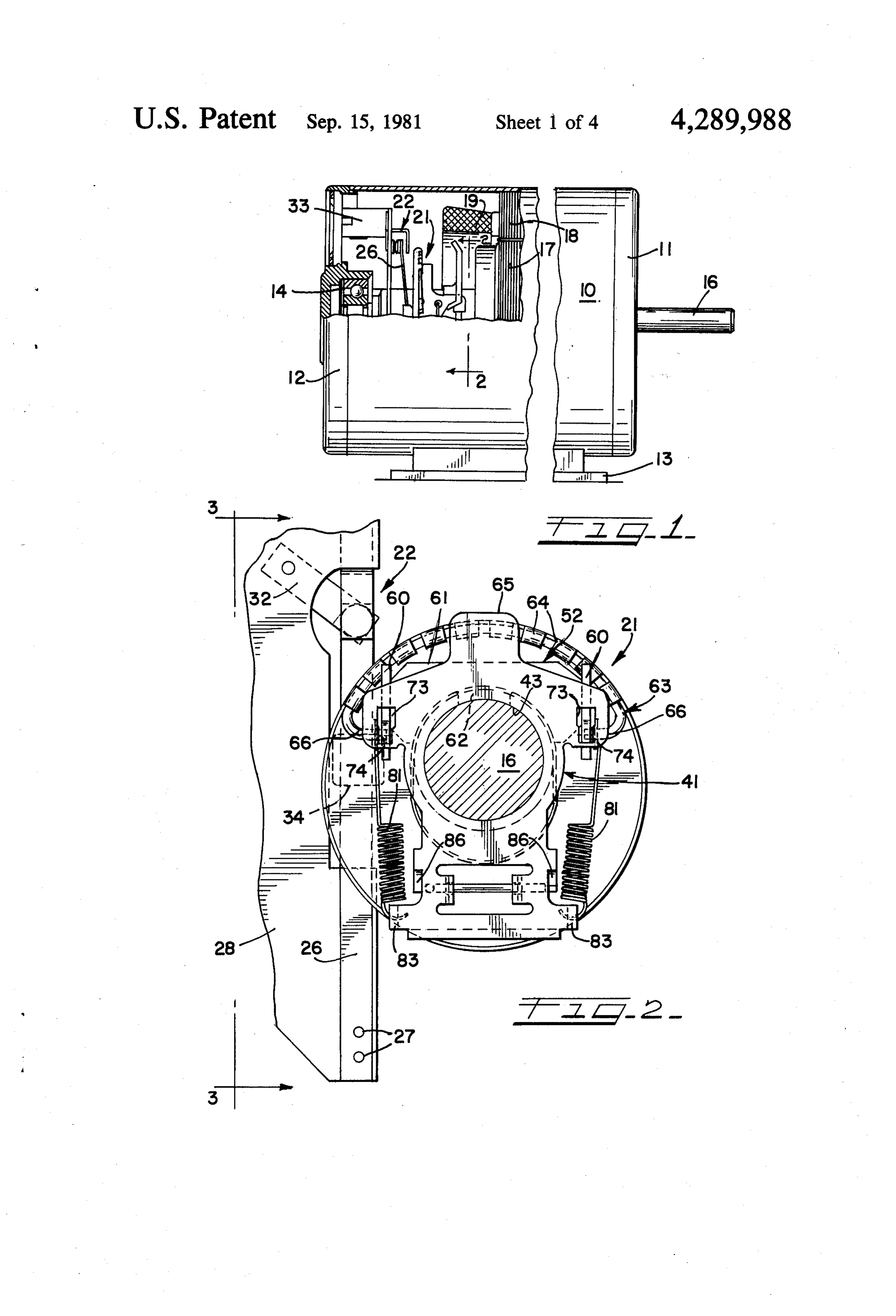
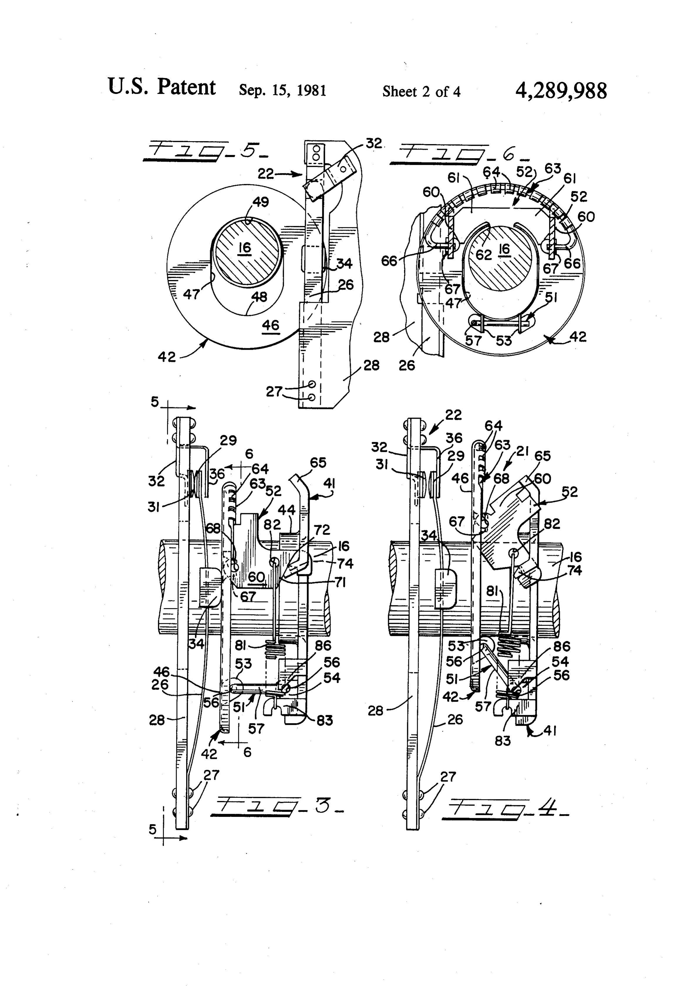
U.S. Pat. No. 2,516,922, No. 3,244,832 and No. FIG. 1 illustrates an electric motor which may have a 3,521,496 disclose different designs of centrifugal mech conventional construction aside from the centrifugal anisms and switches. In. U.S. Pat. No. 2,516,922, the mechanism and switch in accordance with this inven mechanism includes weights which pivot on a support 10 tion. It should be understood that the invention is also part and knife-edge connections are provided between useful in other applications. In the specific example them. The switch includes an annular track and the illustrated, the electric motor includes an outer shell 10 weights are adapted to engage the track in order to secured to two end bells 11 and 12. A mount or stand 13 actuate the switch. While this arrangement has been is connected to the shell 10 and supports the motor. The widely used for many years and has performed well, it 15 end bells 11 and 12 support bearings 14 which in turn is somewhat expensive to manufacture and the provi rotatably support a motor shaft 16 having a rotor 17 sion of the track on the switch has made assembly of the secured thereto. On the inner periphery of the shell 10 motor parts somewhat difficult. is secured a stack of stator laminations 18 and stator U.S. Pat. No. 3,244,832 and No. 3,521,496 show ar windings 19. The motor is of the type wherein the stator rangements where the annular track is provided as part 20 windings 19 include a start winding and a run winding, of the centrifugal mechanism and forms the weight. and a centrifugal mechanism 21 and a switch 22, incor While such arrangements make possible a simplification porating the present invention, are provided to control of the switch, the mechanisms are relatively heavy and energization of the start winding. As is well known to expensive, and they do not have the advantages of the those skilled in the art, at standstill and at low motor low friction knife-edge pivotal connections. 25 speeds, the switch 22 is closed and the motor start wind Morse U.S. Pat. No. 2,610,314 discloses a motor ing is connected in the power supply circuit. At motor speed control system including a centrifugal mechanism speeds above a preset cutout level, the centrifugal wherein an annular track forms part of the centrifugal mechanism 21 operates to open the switch 22 and to mechanism. disconnect the start winding from the power supply It is a general object of this invention to provide an 30 circuit. Of course, when the motor speed slows down improved centrifugal mechanism and switch which again, as when the power is turned off, the shaft 16 overcome the foregoing disadvantages. slows to the level where the centrifugal mechanism 21 In accordance with the present invention, a centrifu again operates to close the switch 22 and reconnect the gal mechanism is provided for connection with a rotat start winding to the power supply circuit in preparation ing shaft, the mechanism comprising a support part 35 for subsequent reenergization of the motor. adapted to be secured to and rotate with the shaft, a With a specific reference to FIGS. 2 to 5, the switch weight pivotally connected to the support part and 22 comprises a switch spring arm 26 having a fixed end having its center of gravity to one side of the axis of the thereof secured as by rivets 27 to a switch mounting and shaft, an annular member pivotally supported by said terminal board 28. The arm 26 extends transversely of weight, and spring means for countering the centrifugal 40 the shaft 16 and closely adjacent the centrifugal mecha force acting on said weight. The annular member is nism 21, and the other or free end of the arm 26 has a pivotally supported for movement through parallel movable switch contact 29 (see FIGS. 3 and 4) secured planes, and it is adapted to engage and actuate a switch to it. A fixed or stationary switch contact 31 is mounted in response to pivoting movement of the weight. The on the board 28 adjacent the movable contact 29, the switch includes an arm adapted to be mounted adjacent 45 stationary contact 31 being supported by an electrically the annular member and to be actuated by movement of conductive leaf 32 (FIGS. 2 to 4). In the present exam the member and the weight. ple, the board 28 is secured to and supported by a mem The foregoing and other objects and advantages of ber 33 (FIG. 1) which in turn is fastened to the end bell the invention will become apparent from the following 12. Of course, the support for the board 28 is intended as detailed description taken in conjunction with the ac- 50 a specific example and a different arrangement may be companying drawings, wherein: provided. The arm 26 and the leaf 32 (FIGS. 2 and 3) FIG. 1 is a view of an electric motor, partially cut are electrically connected in series with the start wind away, including a centrifugal mechanism and switch ing as previously mentioned. At standstill and at low embodying the present invention. motor speeds (see FIG. 3), the two contacts 29 and 31 FIG. 2 is an enlarged sectional view taken on the line 55 are closed by the centrifugal mechanism and the start 2-2 of FIG. 1; winding is connected in the power circuit. On the other FIG. 3 is a fragmentary view taken on the line 3-3 of hand, at running speed of the motor (see FIG. 4), the FIG. 2; two contacts 29 and 31 and the start winding is discon FIG. 4 is a view similar to FIG. 3 but showing differ nected from the power circuit, ent positions of the operating parts. 60 The switch contacts 29 and 31 are of course actuated FIG. 5 is a sectional view on a reduced scale taken on between the open and closed positions by the centrifu the line 5-5 of FIG. 3; and gal mechanism 21 as previously mentioned. An insulat FIG. 6 is a sectional view on a reduced scale taken on ing member or tab 34 (FIGS. 3 and 4) is preferably the line 6-6 of the FIG. 3. secured to the arm 26 approximately midway along its FIG. 7 is similar to FIG. 2 but shows an alternate and 65 length, in the area where the arm 26 extends closest to preferred embodiment of the invention; the centrifugal mechanism 21, and a part 42 (FIGS. 3 FIGS. 8 and 9 are similar to FIGS. 3 and 4 but show and 4) of the mechanism 21 is adapted to engage the tab the embodiment illustrated in FIG. 7; 34 and to close the switch. The switch also includes a
Page 7
finger 36 (FIGS. 3 and 4) fastened to the board 28 adja fingers 64 formed on the edge of the disc 42. The fingers cent the contacts 29 and 31, and the movable contact 29 64 are crimped over and tightly, engage the center sec extends between the stationary contact 31 and the fin tion of the bale 63. The ends of the bale 63 are bent to ger 36. The free end of the arm 26 engages and is re turn laterally inward as indicated by the numeral 66 in strained by the finger 36 when the switch is open, FIG. 6, and the end portions 66 are positioned in thereby controlling the amount of contact opening. notches formed in the ends of a pair of spaced tabs 67 The centrifugal mechanism 21 includes a support part (FIGS. 3, 4 and 6) punched from the disc 62. The end or backplate 41 (FIGS. 3 and 4) which is secured to the portions 66 also extend through pivot holes 68 (FIGS. 3 motor shaft 16. With specific references to FIGS. 2 and and 4) formed in the weight 52. The holes 68 in the 3, the backplate 41 is, in the present example, formed 10 weight 52 are large enough that the end portions 66 of from a piece of flat sheet metal. A circular opening 43 the bale 63 may pivot freely in them. (FIG. 2) is formed in the backplate 41 and a flange or The outer ends of the two arms 60 of the weight 52 collar 44 (FIG. 3) surrounds the opening 43, the internal have notches 71 formed in them, each of the notches 71 diameter of the opening 43 being sized to tightly fit the forming a corner 72. As shown in FIG. 2, the backplate outer surface of the shaft 16. Thus, the backplate 41 is 15 41 has holes 73 formed in it, the two holes 73 being secured to the shaft 16 by an interference fit with the spaced on opposite sides of the center line of the shaft shaft 16. 16. The outer ends of the arms 60 of the U-shaped The centrifugal mechanism 21 further includes a disc weight 52 extend through the holes 73 and the portions 42 (FIGS. 3 and 5) which is, in the present example, 74 (FIGS. 2 and 4) of the backplate 41 containing a formed from a piece of sheet metal and it has a central portion of the holes 73 are bent in the direction of the opening 47 (FIG. 6) that receives the shaft 16. The disc disc 42, as indicated in FIGS. 3 and 4. The corners 72 of 42 is mounted between the backplate 41 and the switch the notches 71 engage the adjacent edges of the holes 73 arm 26. The side 46 (FIGS. 3 and 5) of the disc 42 which and thus form a knife edge engagement as illustrated in is adjacent the arm 26 is flat and smooth and forms a FIG. 3. As previously mentioned, this knife edge en track which is adapted to engage the tab 34 (FIG. 3) 25 gagement reduces the amount of friction between the when the mechanism 41 is in the normal or standstill position. The opening 47 (FIG. 5) is elongated in the weights 52 and the backplate 41. direction of pivoting movement of the disc 42. The distances between totheFIG.
With reference two 3, it will be noted that the arms of the U-shaped hinge opening 47 is larger than the shaft so that the disc 42 is 51 is equal to the distance from the center of the pivot able to pivot without interference from the shaft 16 to holes 68 to the knife edge connections
between the the running position illustrated in FIG. 4. corners 72 of the notches 71 and the edges of the holes The disc 42 is pivotally supported by the backplate 41, and the pivotable connection is formed by parallel 73. As the disc 42 swings or pivots relative to the back plate 41, the arms of the hinge 51 turn in the mounting arms so that the track or surface 46 of the disc 42 is maintained perpendicular to the axis of the shaft 16 and 35 the holes in the tabs 53 and 54 and the weight 52 pivots on parallel to the main part of the backplate 41 during the end portions 66 of the bale 63 and on the knife edge . pivoting movement. The pivotal connection between pivots. 46 of
Due to the parallel arm arrangement, the surface the disc 42 is maintained parallel to the backplate the backplate 41 and the disc 42 is formed by a hinge 51 41 and perpendicular
(FIG. 3) and by a weight 52. Two spaced tabs 53 (FIG. pivoting movement. to the axis of the shaft 16 during 6) are formed on the disc 42 and the two spaced tabs 54 40 As shown in FIGS. 2 to 4, connected between the (FIGS. 3 and 4) are formed on the backplate 41, the tabs backplate being formed as by punching and bending, and a pivot springs 81 41which and the weight 52 are a pair of tension counter the centrifugal force, one of hole 56 is formed in each of the tabs. As shown in FIG.
6, the two tabs 53 on the movable disc 42 are spaced on the springs 81 being located on each side of the axis of opposite sides of the center line or axis of rotation of the 45 the shaft 16. Each of the arms 60 of the weight 52 has a shaft 16, and the two tabs 54 on the backplate 41 are hole 82 formed in it, and one end of a spring 81 is con similarly spaced. The hinge 51 (FIGS. 3 and 6) has a nected in one of the holes 82. The other ends of the two U-shaped configuration, one arm of the U extending springs 81 are connected to the opposite side of the through the holes in the tabs 54, and the center portion backplate adjacent the hinge 51. Two tabs 83 are 57 of the U extending between the tabs 53 and 54 and 50 formed on the backplate 41 adjacent the hinge 51, and forming a hinge arm. the turned ends of the springs 81 are connected to The weight 52 (FIGS. 3 and 4) serves as both a cen notches formed in the tabs 83. As shown in FIGS. 2 and trifugal weight and as a hinge or pivot connection, and 6, the weight 52 extends over one side of the shaft 16, in the present instance it is formed from a piece of sheet which is the side opposite from the tabs 83, and the two metal which is bent to a generally U-shape. The center 55 tension springs 81 urge the weight 52 to the position or connecting part of the U extends laterally of the shaft shown in FIGS. 2 and 3 where the portion 62 of the 16 and is indicated by the numeral 61 in FIG. 6, and the weight 52 engages the upper side of the shaft. This, of two arms 60 of the weight 52 extend parallel to the shaft course, is the normal or standstill position of the centrif 16 and they extend between the members 41 and 42 (see ugal mechanism. In the running position of the mecha FIG. 3). A radial projection 62 (FIG. 6) at the middle of 60 nism shown by FIG. 4, the center portion 61 of the the connecting portion 61 is shaped to conform to and weight 52 engages a stop 65 formed on the upper end of engage the outer surface of the motor shaft 6 when the the backplate 41.
centrifugal mechanism is in the normal or standstill At the two ends of the hinge 5i arm which is con position, as shown in FIG. 6, and the connecting por nected to the backplate 41 are formed two locking tabs tion 61 extends transversely of and across the shaft 6. 65 86 (FIGS. 2 to 4) which extend across the outer ends of The weight 52 is pivotally connected to the movable the hinge 51. The tabs 86 are punched from the plate 41 disc 42 by a generally U-shaped bale 63 (FIGS. 2 to 4) and prevent the hinge 51 from moving out of place which is secured to the movable disc 42 by a plurality of during use of the mechanism. A corner of at least one of
Page 8
the two tabs 86 is cut away to permit assembly of the the connecting portion 118, the bale 112 angles or slants parts, as will be described in connection with FIG. 11. upwardly and toward the right from its end portions Regarding the distribution of weight in the centrifu 114. The bale and the weight are assembled by position gal mechanism, the weight 22 is to one side of the motor ing the end portions 114 in the notches 131 and snapping shaft 16 axis, and therefore its center of gravity is dis the central portion 113 over the tab 121. The length of placed from the shaft axis. The disc 42 is preferably the tab 121 and the above-mentioned angle ensure a unbalanced and has more weight on the side toward the secure connection of the parts and location of the bale weight 52, this unbalance being produced by the bale 112.
63, in the specific example being described. In other FIG. 10 illustrates the knife-edge pivot connection forms of the invention, the weight of the disc 42 may be 10 between the weight 109 and the backplate 106. Each distributed to obtain the desired operating characteris arm 117 of the weight 109 has a notch 122 formed in it tics. The rotation of the shaft produces a centrifugal and each notched portion extends through a hole 123 force on the weight 52 and on the disc 42, and the (FIGS. 10 and 12) formed in the backplate 106. Knife springs 81 produce a counterforce. When the weight 52 edges or corners are formed as indicated at 124, which starts to swing outwardly on the knife edges, the cen 15 form a low friction pivot connection between the trifugal force increases, causing a snap action. The force weight 109 and the backplate 106. The mechanism on the disc 42 of the switch arm 26 is axially directed shown in FIGS. 1 to 6 has the same pivot connection and the pivot axis of the hinge 51 and the weight 52 are shown in FIG. 10.
axially aligned when in the standstill position, and con The arrangement of the bale shown in FIGS. 7 to 9 is sequently the arm 26 force does not tend to pivot the 20 advantageous because the disc 107 does not carry the disc 42. When in the running position shown in FIG.4, weight of the bale 112. The disc is not therefore subject the centrifugal mechanism as a whole is substantially to failure due to the weight of the bale. Further, the balanced around the shaft 16 axis. assembly of the bale with the weight as shown in FIGS. FIGS. 7 to 14 illustrate an alternate and preferred 7 to 9 is simpler than the assembly method to produce form of the centrifugal mechanism, indicated by the 25 the construction of FIGS. 1 to 6 because it is not neces reference numeral 101. The mechanism 101 is secured sary to crimp a plurality of small fingers. Aside from the to a motor shaft 102 adjacent a switch 103 that may be differences noted above, the construction and operation the same as the switch 22. The mechanism 101 includes of the centrifugal mechanism 101 and the switch 103 are a backplate 106, a disc 107, a U-shaped hinge 108, and a the same as the arrangement shown in FIGS. 1 to 6. At weight 109 that also acts as a hinge. 30 standstill and at low motor speeds, the disc 107 and the The disc 107 is similar to the disc 42, the difference weight 109 are held in the position shown in FIG. 8 by being that the disc 107 does not include the clinched or a pair of springs 126, but as the motor approaches run crimped fingers 64. The disc 107 includes a circular ning speed, the centrifugal force acting on the weight flange or lip 111 at its outer edge that serves to stiffen 109 and the bale 112 causes the parts to swing with a the disc. 35 snap action to the FIG. 9 position. The weight 109 has The weight 109 (FIGS. 7 to 9, 13 and 14) is con a relatively thick, heavy construction and therefore is structed similarly to the weight 52, the difference being able to support the weight of the bale 112 without fail that the weight 109 is designed to be secured to a bale ing, in spite of the snap action mode of operation. Fur 112 that swings with the weight. In the mechanism ther, the arrangement shown in FIGS. 7 to 9 comprises shown in FIGS. 1 to 6, the bale 63 is secured to the disc a simplified method of assembling the bale with the 42 by the crimped fingers 64, and end portions 66 of the other parts of the mechanism.
bale form pivot connections between the disc and the Regarding the U-shaped hinge 108, two tabs 127 weight. In the mechanism shown in FIGS. 7 to 14, in (FIGS. 8, 9, 11 and 12) extend across the ends of the order to reduce the total weight of the disc and to form hinge to hold it assembled with the mechanism. With a more rugged support for the bale, the bale 112 is se 45 reference to FIG. 11, the solid line position of the hinge cured to and swings with the weight 109. 108 shows the standstill position illustrated in FIG. 8, With reference to FIG. 7, the central portion 113 of and the upper dash line position shows the running the bale 112 is generally semi-circular and extends over position illustrated in FIG. 9. One of the tabs 127 has a the side of the shaft 102 which is adjacent the weight corner removed as indicated at 128 to permit assembly 109. The end portions 114 of the bale 112 are bent out 50 with the hinge 108. Before the centrifugal mechanism is wardly as shown in FIG. 7 and extend through pivot mounted on the shaft 102, the hinge 108 is placed in the holes formed in two tabs 116 formed on the disc 107. lower dash line position shown in FIG. 11 where it The weight includes a central connecting portion 118 clears the tab 127 having the removed corner 128. After (FIGS. 7, 13, and 14) that extends transversely across assembly with the backplate 106 and the disc 107, the the shaft 102 between the arms 117, and the central 55 hinge 108 is pivoted to the standstill and running posi portion 113 of the bale extends closely adjacent the tions, and the tab 127 prevents removal of the hinge 108. connecting portion 118. A radial projection 119, similar The operation of the two forms of the centrifugal to the projection 62, has a tab 121 bent to extend under mechanism and the switch is similar. With reference to the central portion 113 of the bale 112. Thus, the bale the form shown in FIGS. 1 to 7, assume that the motor 112 is secured to and swings with the weight 109. Each 60 is de-energized and that the motor shaft is stationary. arm 117 of the weight 109 has a notch or slot 131 (FIG. The two tension springs 81 hold the weight 52 in the 14) formed in it which receives the end portions 114 of standstill position where the projection 62 engages the the bale 112. The provision of the notches 131 is pre surface of the shaft 16 (FIGS. 3 and 6). The centrifugal ferred for the weight 109, instead of pivot holes, be mechanism 21 is mounted on the shaft 16 adjacent the cause it simplifies the assembly of the parts. FIG. 14 65 switch 22 and close enough that the disc track or sur shows in dashed lines the position of the bale 112 on the face 46 engages the tab 34 (FIG. 3) and exerts pressure weight 109, and it will be noted that, due to an offset of on the tab 34 to press the contact 29 into engagement the notches 131 relative to the right-hand surface 132 of with the stationary contact 31. As previously men
Page 9
tioned, in this position of the switch contacts the start axially spaced and the pivotal connections to said hinge winding circuit of the motor is connected to be ener are axially spaced.
gized by the power supply. When the power supply is 6. A mechanism as in claim 1, wherein said weight is turned on, the shaft 16 turns and the centrifugal force pivotally connected to said annular member by bale acting on the weight 52 causes the disc 42 to swing and means, said weight and said annular member having open the switch contacts 29 and 31 at a predetermined pivot means formed therethrough and end portions of shaft speed (as shown by FIG. 4). When the shaft is said7. bale means extending through said end means. A mechanism as in claim 6, wherein said bale turning at lower than running speed, the tab 34 slides on means is attached to said weight. the surface 46 as the mechanism 21 turns. This surface, 8. A mechanism as in claim 7, wherein said bale of course, is maintained in parallel planes as the disc 42 10 means swings between its two positions. When the motor tab, saidincludes a center part and said weight includes a speed subsequently slows down, the spring 81 force means andbale extending at an angle between said pivot said tab.
overcomes the centrifugal force and the disc 42 swings 9. A mechanism as in claim 6, wherein said bale back to the FIG. 3 position and the contacts 29 and 31 means is attached to said annular member. reclose. 15 10. A mechanism as in claim 6, wherein said pivot Apparatus in accordance with the invention has a means comprises holes in said annular member and number of advantages. The switch is relatively uncom plicated and reliable, and it simplifies the assembly of notches11. A in said weight.
mechanism as in claim 6, wherein said pivot the motor parts. The two forms of the mechanism uti means comprises holes in said weight and notches in lize the low friction knife-edge pivot connections which 20 said annular member.
support the weight, and the knife-edge connection has 12. In an electric motor including a shaft that is rotat an extremely long life. The discs that form the switch able on an axis, the improvement comprising a centrifu engaging track are lightweight and readily supported, gal mechanism and switch assembly, said mechanism and consequently they do not excessively wear the comprising a support part secured to and rotating with pivot hinge connections. The weight is acted upon only the shaft, a movable annular member having a central by the centrifugal force and the springs, and it may be 25 opening receiving the shaft therethrough, a weight calibrated before being assembled with the shaft and the having its center of gravity to one side of the axis of switch. rotation of the shaft, said weight extending between said I claim: support part and said annular member and being pivot 1. In an electric motor including a rotatable shaft and ally connected directly to said part and to said member, a switch connected to control energization of a winding 30 said weight and said annular member having a standstill of the motor, the improvement comprising a centrifugal position that exists when said shaft is stationary and a mechanism for actuating the switch, said mechanism running position that exists when said shaft is turning at comprising a support part secured to and rotating with above a predetermined speed, centrifugal force acting the shaft, a movable annular member having a central 35 on said weight and causing pivotal movement of said opening receiving the shaft therethrough, a weight weight and said member to said running position, and having its center of gravity to one side of the axis of counterforce means directly said weight and said sup rotation of the mechanism and the shaft, said weight port part and extending therebetween and causing extending between said support part and said annular movement to said standstill position, said switch assem member and being pivotally connected to said part and bly being mounted adjacent and being engageable by said member, said weight and said member swinging 40 said annular member and movement of said annular outwardly due to centrifugal force upon rotation of said member acting to actuate said switch assembly. mechanism, said weight and said annular member hav 13. An assembly as in claim 12, wherein said switch arm ing a standstill position that exists when said mechanism the otherand support means secured to one end of said arm, end of said arm forming a movable contact, a is stationary and a running position that exists when said 45 fixed contact mechanism is turning at above a predetermined speed, said movable mounted contact, on said support means adjacent said arm extending transversely centrifugal force acting on said weight and causing said outward swinging movement to said running position, of the shaft and closely adjacent said annular member, said annular member forming a track which is engaga and counterforce means directly connected to said ble weight and said support part and extending therebe 50 14.with An said arm.
assembly as in claim 13, wherein said switch tween and causing movement to said standstill position, further includes a tab attached to said arm and adapted said annular member being adapted to engage said to engage said arm.
switch and said swinging movement of said annular 15. A centrifugal mechanism for actuating a switch member being adapted to actuate the switch. comprising a rotatable support part adapted to be ro 2. A mechanism as in claim 1, wherein said annular tated on an axis, a movable part connected to said sup member is unbalanced around the shaft axis when in 55 port part and movable between a standstill position and said standstill position. a running position, said movable part comprising a 3. A mechanism as in claim 1, wherein said weight weight having one end thereof pivotally attached to and said pivotal connections thereto are on said one side said support part, said weight having its center of grav of said axis, and a hinge is pivotally connected between ity to one side of the axis and the centrifugal force due said annular member and said part on the side of the axis 60 to rotation of said mechanism operating to pivot said which is opposite said one side, said hinge and said weight toward said one side, counterforce means di weight forming a parallel arm connection. rectly connected to said weight and said support part 4. A mechanism as in claim 1, wherein said pivotal and extending therebetween and countering said cen connection between said weight and said support part is trifugal force, and an annular member pivotally con a knife-edge pivot connection. 65 nected directly to the other end of said weight and 5. A mechanism as in claim 3 wherein, when said carried by said weight in said pivoting movement and weight and said annular member are in the standstill pivotally connected skto said k support
part by said weight.
position, the pivotal connections to said weight are
Provenance
- Collection
- Cited prior art
- Original PDF
- patentimages.storage.googleapis.com →
- Filed
- 1979-10-05
- Pages
- 9
- Method
- pdftotext (the PDF's own text layer) + pdftoppm 300dpi page scans
- Source
- Google Patents bibliographic record
- Granted
- 1981-09-15
- Inventors
- Edward J. Schaefer; Franklin Electric Co Inc
- Transcribed from
- patentimages.storage.googleapis.com →