patent · US4782256
Electricity generator for wheel detection
1 November 1988
Page 1 — bibliographic record
United States Patent (19) 11 Patent Number: 4,782,256 Kokubu 45 Date of Patent: Nov. 1, 1988 (54 ELECTRICITY GENERATOR FOR WHEEL FOREIGN PATENT DOCUMENTS
DETECTION
75 Inventor: Sadao Kokubu, Aichi, Japan 490551 2/1953 Canada ............................. 310/67 A.
73) Assignee: Kabushiki Kaisha Tokai Rika Denki 265700 3/1947 Switzerland ...................... 310/67. A Seisakusho, Japan Primary Examiner-Patrick R. Salce 21 Appl. No.: 90,543 Assistant Examiner-D. L. Rebsch (22 Filed: Aug. 28, 1987 Attorney, Agent, or Firm-Finnegan, Henderson, Farabow, Garrett and Dunner (30) Foreign Application Priority Data 57 ABSTRACT
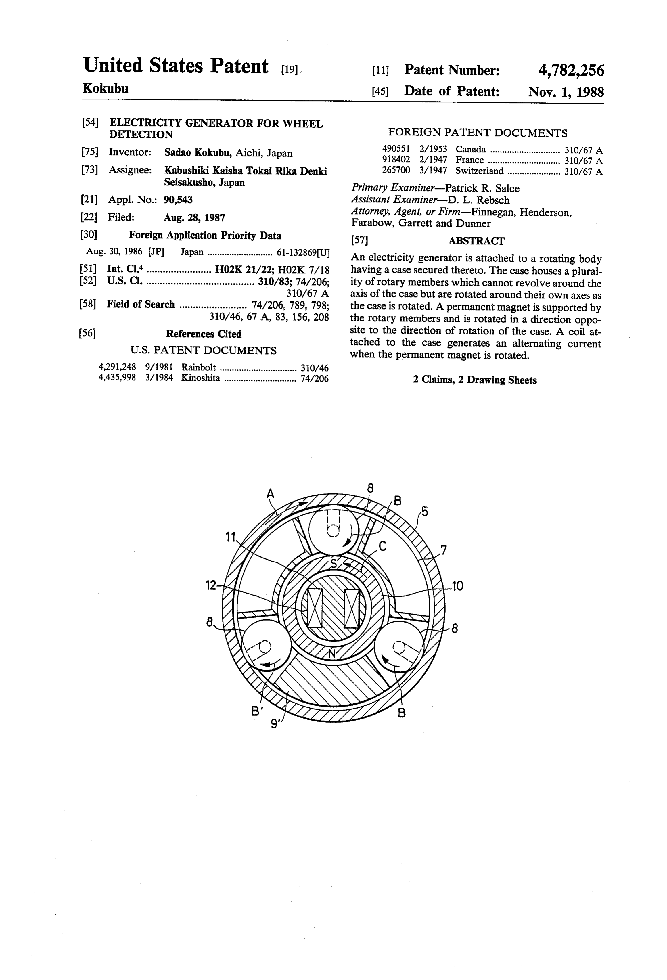
Aug. 30, 1986 JP Japan ........................... 61-132869(U An electricity generator is attached to a rotating body 51) Int. Cl."........................ H02K 21/22; HO2K7/18 having a case secured thereto. The case houses a plural 52 U.S. Cl. ........................................ 310/83; 74/206; ity of rotary members which cannot revolve around the 310/67 A axis of the case but are rotated around their own axes as 58 Field of Search ......................... 74/206, 789, 798; the case is rotated. A permanent magnet is supported by 310/46, 67 A, 83, 156, 208 the rotary members and is rotated in a direction oppo (56) References Cited site to the direction of rotation of the case. A coil at
when the permanent magnet is rotated.
4,291,248 9/1981 Rainbolt ................................ 30/46 4,435,998 3/1984 Kinoshita .............................. 74/206 2 Claims, 2 Drawing Sheets
Page 2
Drawing sheet — no readable text.
Page 3
Drawing sheet — no readable text.
Page 4
FIG. 2 shows a cross-sectional view of the major part
ELECTRICTY GENERATOR FOR WHEEL of the electricity generator;
DETECTION FIG. 3 shows a longitudinally sectional view of a wheel; and
FIELD OF THE INVENTION FIG. 4 shows an electric circuit diagram. The present invention relates to an electricity genera DETAILED DESCRIPTION tor attached to a rotating body.
As shown in FIG. 3, a shaft 2 is coupled to the rim 1
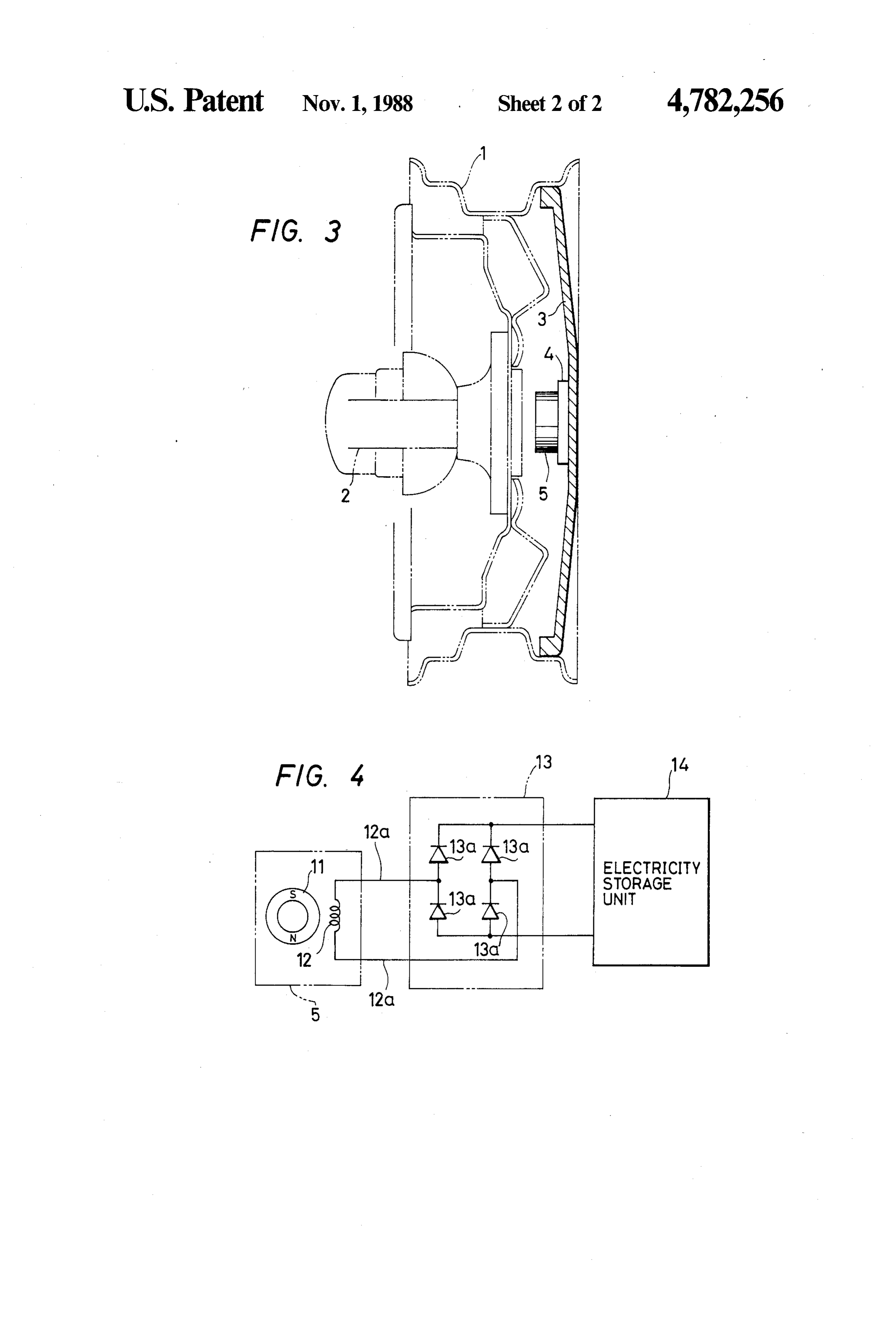
BACKGROUND OF THE INVENTION of the wheel of a motor vehicle. A plastic hubcap 3, which is a rotating body, is attached to the rim 1. A
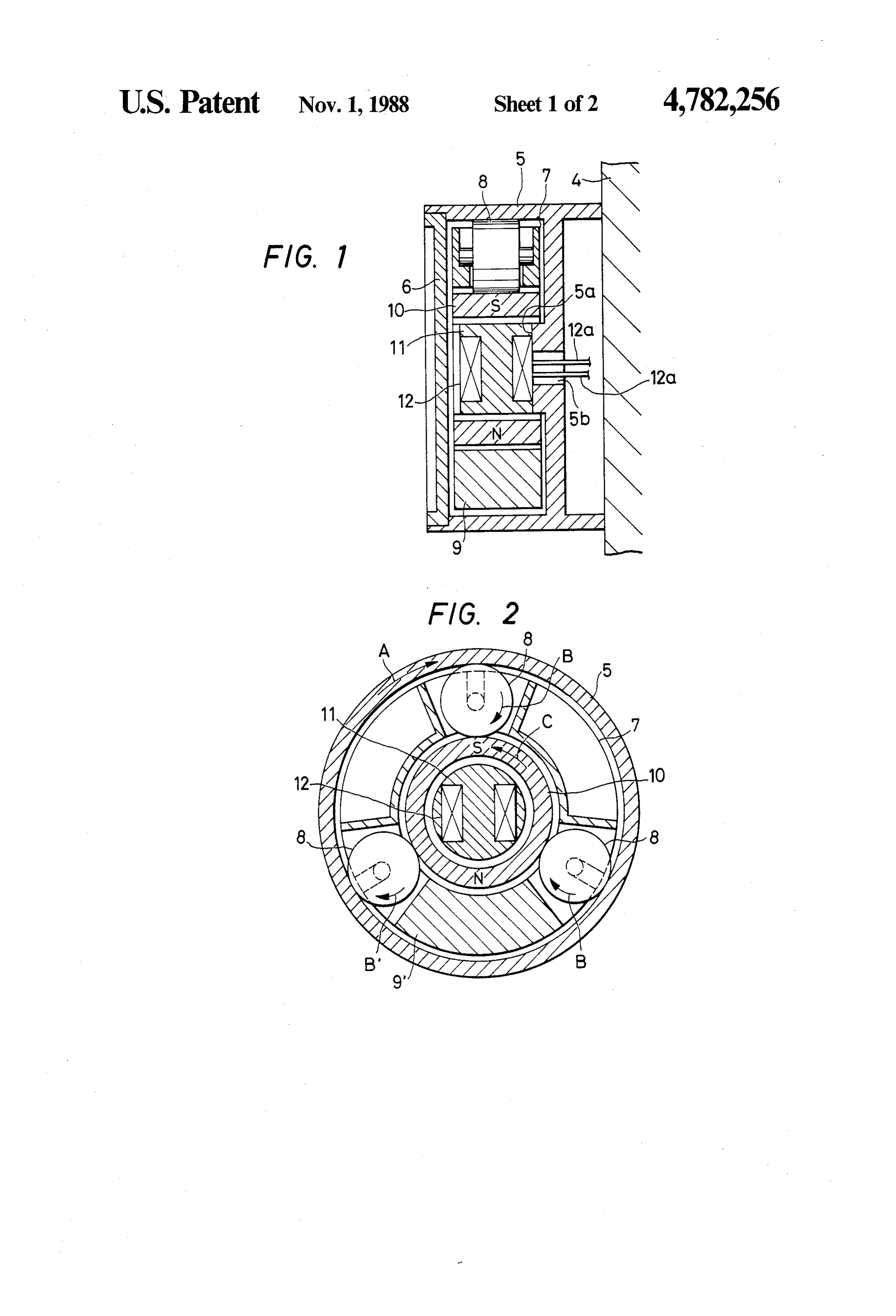
A detector, which detects such conditions of a wheel 10 circular of a motor vehicle as the decrease in the air pressure of inside attaching portion 4 is integrally formed on the a tire on the wheel and the wear of the tire and then surface of the central portion of the hubcap 3. A gives a warning, has been proposed. The detector, circular case 5 is secured to the attaching portion 4. The which rotates together with the wheel, needs a power axis of the shaft 2 and that of the hubcap 3 are coinci supply such as a dry cell, a solar cell, or an electricity 15 dent with that of the case 5. generator comprising a permanent magnet on the side 5 isAsopen, shown in FIG. 1, the inner end portion of the case and an inward projection 5a is provided on of the chassis of the motor vehicle and a coil on the side the central of the wheel. A dry cell used as the power supply has a wire insertion portion of the wall of the case and has a lead drawback that the life of the dry cell is so short that the 20 inner end portionhole 5b. A cover 6 is fitted in the open dry cell needs to be replaced at regular intervals. The of the case 5. use of a solar cell as the power supply has a drawback disposed in the case 5.1Three
As shown in FIGS. and 2, a hollow holder 7 is rotary members 8 are that the solar cell is affected by the weather and time of supported at equiangular intervals by the holder 7 so the day so that the solar cell cannot produce any elec that the rotary members 8 can rotate tricity in rainy weather and at night. The difficulty with 25 thereof. The peripheral portions of the around rotary the axes members using an electricity generator as the power supply se cured to a wheel is that is is difficult in assembling the 8portions project out of the inside and outside circumferential electricity generator to adjust the positional relation the insideof circumferential the holder 7 and are located in contact with surface of the case 5. A between the permanent magnet and coil at the electric weight 9 is attached to the lower portion of the holder ity generator because the chassis and wheel of the 30 7 so that the holder is unrotatable and maintained sub motor vehicle are coupled to each other by an elastic stantially stationary. An annular permanent magnet 10, suspension. one half circumferential portion of which has a south OBJECTS AND SUMMARY OF THE pole and the other half circumferential portion of which INVENTION has a north pole, is disposed in the case 5 in such a 35 manner that the permanent magnet is supported on the
Accordingly, it is an object of the present invention outside circumferential surface thereof by the periph to provide an electricity generator that may be attached eral portions of the three rotary members 8. A core 11 to a rotating body, is easy to assemble, has a long life is attached to the projection 5a of the case 5 and located and is not affected by the weather and the time of day. in the permanent magnet 10. A coil 12 is provided on The electricity generator of the present invention is the core 11, and lead wires 12a connected to the coil 12 characterized in that a case is attached to the rotating extend out through the lead wire insertion hole 5b of the body and a plurality of rotary members are supported in projection 5a of the case 5.
contact with the inside circumferential surface of the As shown in FIG. 4, the lead wires 12a are connected case, so that the rotary members cannot be revolved to the AC input terminals of a rectifying circuit 13 around the axis of the case but are rotated around the 45 which comprises four diodes 13a connected together in axes of the rotary members as the case is rotated. A a bridge and whose DC output terminals are connected permanent magnet is supported by the rotary members to the terminals of an electricity storage unit 14. so that the permanent magnet is rotated in a direction The operation of the embodiment is now described. opposite to that of the rotation of the case, as the rotary When the motor vehicle is started, the hubcap 3 is ro members are rotated around the axes thereof. A coil is 50 tated together with the wheel of the vehicle so that the attached to the case so that an alternating current is attaching portion 4 is rotated. As a result, the case 5 caused to flow through the coil as the permanent mag attached to the portion 4 is also rotated in a direction A net is rotated. so that the core 11 attached to the case and the coil 12 Since the permanent magnet is rotated in a direction provided on the core are also rotated in the direction A. opposite to that of the rotation of the case, the relative 55 At that time, the three rotary members 8 located in rotation speed between them is so high that sufficient contact with the inside circumferential surface of the alternating current is caused to flow through the coil by case 5 are rotated around the axes of the rotary mem the magnetic flux of the permanent magnet even if the bers in a direction B. Since the holder 7 is kept unrotata rotating body that rotates the case is slowly rotated. ble or nearly stationary by the weight 9, the three rotary Since the electricity generator is constituted as de members 8 cannot revolve around the axis of the case 5. scribed above, the electricity generator has a long life, is Since the three rotary members 8 are rotated around the easy to assemble and is not affected by the weather and axes thereof in the direction B, the permanent magnet the time of the day. 10 supported by the rotary members is rotated in a BRIEF DESCRIPTION OF THE DRAWINGS 65 alternatingC opposite direction to the direction A. As a result, an magnetic field is applied to the core 11
FIG. 1 shows a longitudinal sectional view of a major through the north and south poles of the permanent part of an electricity generator according to an embodi magnet 10 to cause an alternating current to flow ment of the present invention; through the coil 12. The alternating current is rectified
Page 5
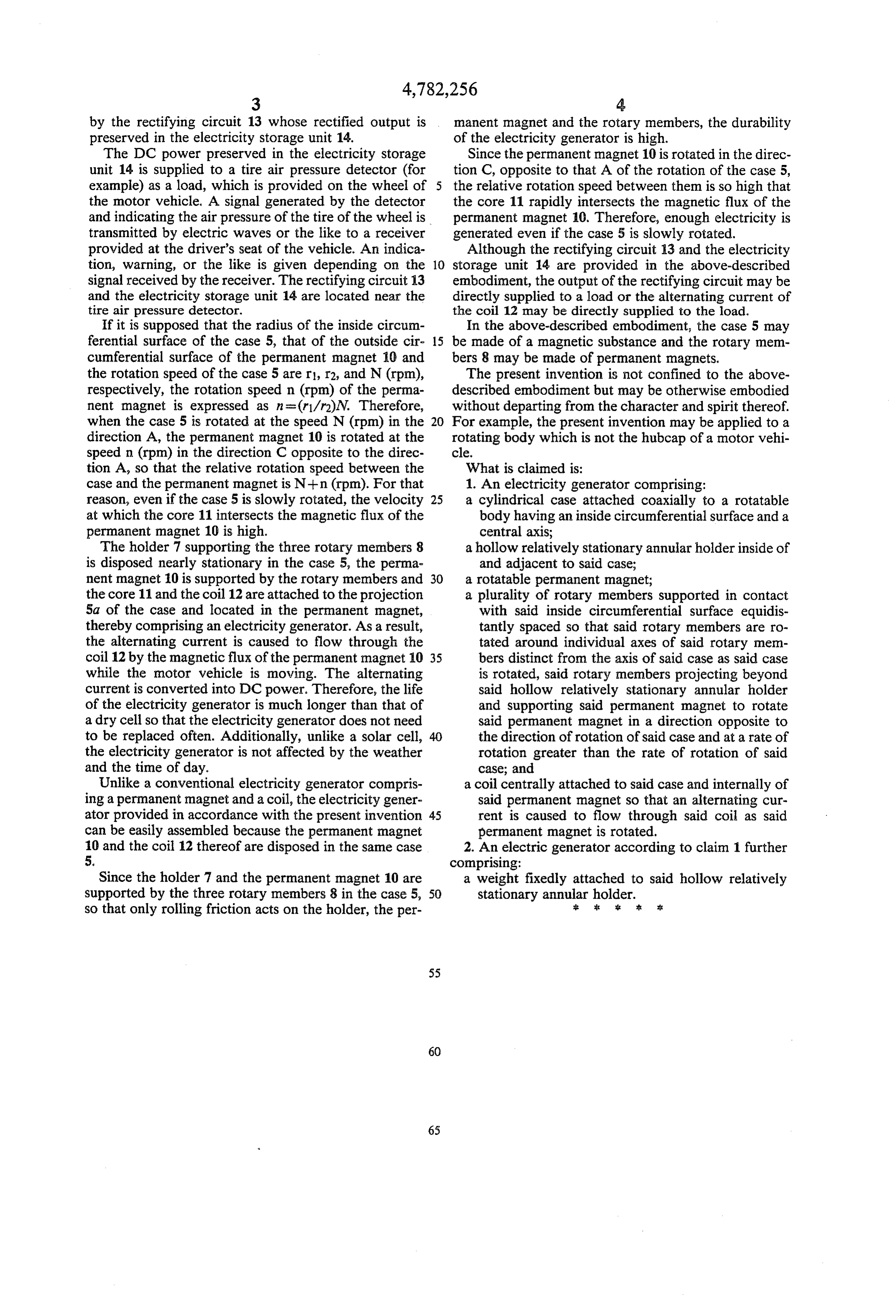
by the rectifying circuit 13 whose rectified output is manent magnet and the rotary members, the durability preserved in the electricity storage unit 14. of the electricity generator is high. The DC power preserved in the electricity storage Since the permanent magnet 10 is rotated in the direc unit 14 is supplied to a tire air pressure detector (for tion C, opposite to that A of the rotation of the case 5, example) as a load, which is provided on the wheel of 5 the relative rotation speed between them is so high that the motor vehicle. A signal generated by the detector the core 11 rapidly intersects the magnetic flux of the and indicating the air pressure of the tire of the wheel is permanent magnet 10. Therefore, enough electricity is transmitted by electric waves or the like to a receiver generated even if the case 5 is slowly rotated. provided at the driver's seat of the vehicle. An indica Although the rectifying circuit 13 and the electricity tion, warning, or the like is given depending on the 10 storage unit 14 are provided in the above-described signal received by the receiver. The rectifying circuit 13 embodiment, the output of the rectifying circuit may be and the electricity storage unit 14 are located near the directly supplied to a load or the alternating current of tire air pressure detector. the coil 12 may be directly supplied to the load. If it is supposed that the radius of the inside circum In the above-described embodiment, the case 5 may ferential surface of the case 5, that of the outside cir- 15 be made of a magnetic substance and the rotary mem cumferential surface of the permanent magnet 10 and bers 8 may be made of permanent magnets. the rotation speed of the case 5 are r1, r2, and N (rpm), The present invention is not confined to the above respectively, the rotation speed n (rpm) of the perma described embodiment but may be otherwise embodied nent magnet is expressed as n = (r1/r2)N. Therefore, without departing from the character and spirit thereof. when the case 5 is rotated at the speed N (rpm) in the 20 For example, the present invention may be applied to a direction A, the permanent magnet 10 is rotated at the rotating body which is not the hubcap of a motor vehi speed n (rpm) in the direction C opposite to the direc cle.
tion A, so that the relative rotation speed between the What is claimed is:
case and the permanent magnet is N--n (rpm). For that 1. An electricity generator comprising: reason, even if the case 5 is slowly rotated, the velocity 25 a cylindrical case attached coaxially to a rotatable at which the core 11 intersects the magnetic flux of the body having an inside circumferential surface and a permanent magnet 10 is high. central axis;
The holder 7 supporting the three rotary members 8 a hollow relatively stationary annular holder inside of is disposed nearly stationary in the case 5, the perma and adjacent to said case; nent magnet 10 is supported by the rotary members and 30 a rotatable permanent magnet;
the core 11 and the coil 12 are attached to the projection a plurality of rotary members supported in contact 5a of the case and located in the permanent magnet, with said inside circumferential surface equidis thereby comprising an electricity generator. As a result, tantly spaced so that said rotary members are ro the alternating current is caused to flow through the tated around individual axes of said rotary men coil 12 by the magnetic flux of the permanent magnet 10 35 bers distinct from the axis of said case as said case while the motor vehicle is moving. The alternating is rotated, said rotary members projecting beyond current is converted into DC power. Therefore, the life said hollow relatively stationary annular holder of the electricity generator is much longer than that of and supporting said permanent magnet to rotate a dry cell so that the electricity generator does not need said permanent magnet in a direction opposite to to be replaced often. Additionally, unlike a solar cell, 40 the direction of rotation of said case and at a rate of the electricity generator is not affected by the weather rotation greater than the rate of rotation of said and the time of day. case; and
Unlike a conventional electricity generator compris a coil centrally attached to said case and internally of ing a permanent magnet and a coil, the electricity gener said permanent magnet so that an alternating cur ator provided in accordance with the present invention 45 rent is caused to flow through said coil as said can be easily assembled because the permanent magnet permanent magnet is rotated. 10 and the coil 12 thereof are disposed in the same case 2. An electric generator according to claim 1 further 5. comprising:
Since the holder 7 and the permanent magnet 10 are a weight fixedly attached to said hollow relatively supported by the three rotary members 8 in the case 5, 50 stationary annular holder. k so that only rolling friction acts on the holder, the per is
Provenance
- Collection
- Cited prior art
- Original PDF
- patentimages.storage.googleapis.com →
- Filed
- 1987-08-28
- Pages
- 5
- Method
- pdftotext (the PDF's own text layer) + pdftoppm 300dpi page scans
- Source
- Google Patents bibliographic record
- Granted
- 1988-11-01
- Inventors
- Sadao Kokubu; Tokai Rika Co Ltd
- Transcribed from
- patentimages.storage.googleapis.com →