patent · US3992132
Energy conversion system
16 November 1976
Page 1
United States Patent (19) 11, 3,992,132 Putt (45) Nov. 16, 1976 54) ENERGY CONVERSION SYSTEM Primary Examiner-William L. Freeh 76) Inventor: J. William Putt, 3278 West Cedar Assistant Examiner-G. P. LaPointe St., Allentown, Pa. 18104 Attorney, Agent, or Firm-Beveridge, DeGrandi, Kline & Lunsford
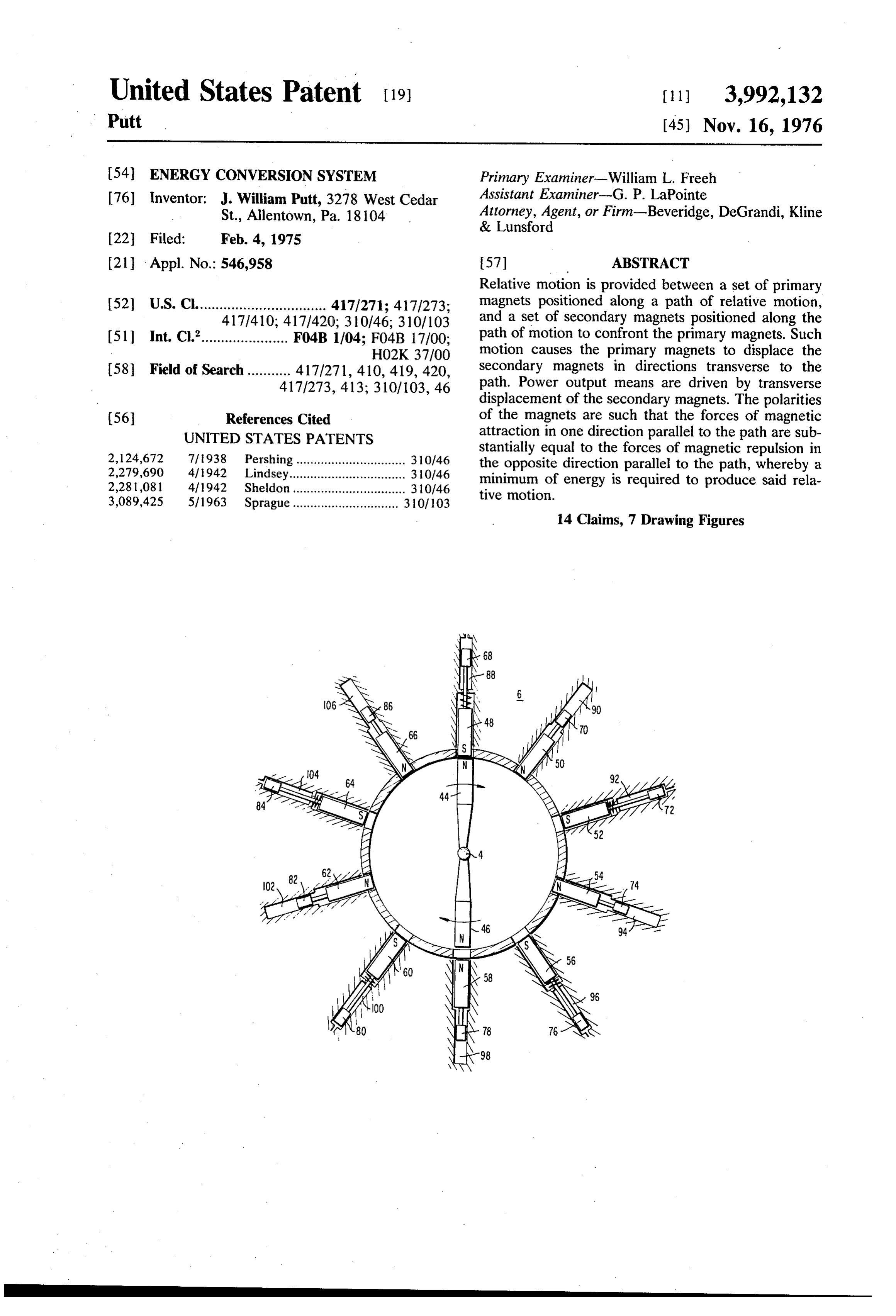
21 Appl. No.: 546,958 57 ABSTRACT Relative motion is provided between a set of primary (52) U.S. Cl................................. 417/271; 417/273; magnets positioned along a path of relative motion, 417/410; 417/420; 310/46; 310/103 and a set of secondary magnets positioned along the 51 Int. C.’...................... F04B 1/04; F04B 17700; path of motion to confront the primary magnets. Such HO2K 37/00 motion causes the primary magnets to displace the 58 Field of Search........... 417/271, 410, 419, 420, secondary magnets in directions transverse to the 417/273, 413; 310/103, 46 path. Power output means are driven by transverse displacement of the secondary magnets. The polarities (56) References Cited of the magnets are such that the forces of magnetic attraction in one direction parallel to the path are sub
UNITED STATES PATENTS
2,124,672 7/1938 Pershing............................... 310/46 stantially equal to the forces of magnetic repulsion in 2,279,690 4/1942 Lindsey... ... 30.146 the opposite direction parallel to the path, whereby a 2,281,081 4/1942 Sheldon. ... 310/46 minimum of energy is required to produce said rela 3,089,425 5/1963 Sprague.............................. 310/103 tive motion.
14 Claims, 7 Drawing Figures
Page 2
Drawing sheet — no readable text.
Page 3
Drawing sheet — no readable text.
Page 4
Drawing sheet — no readable text.
Page 5
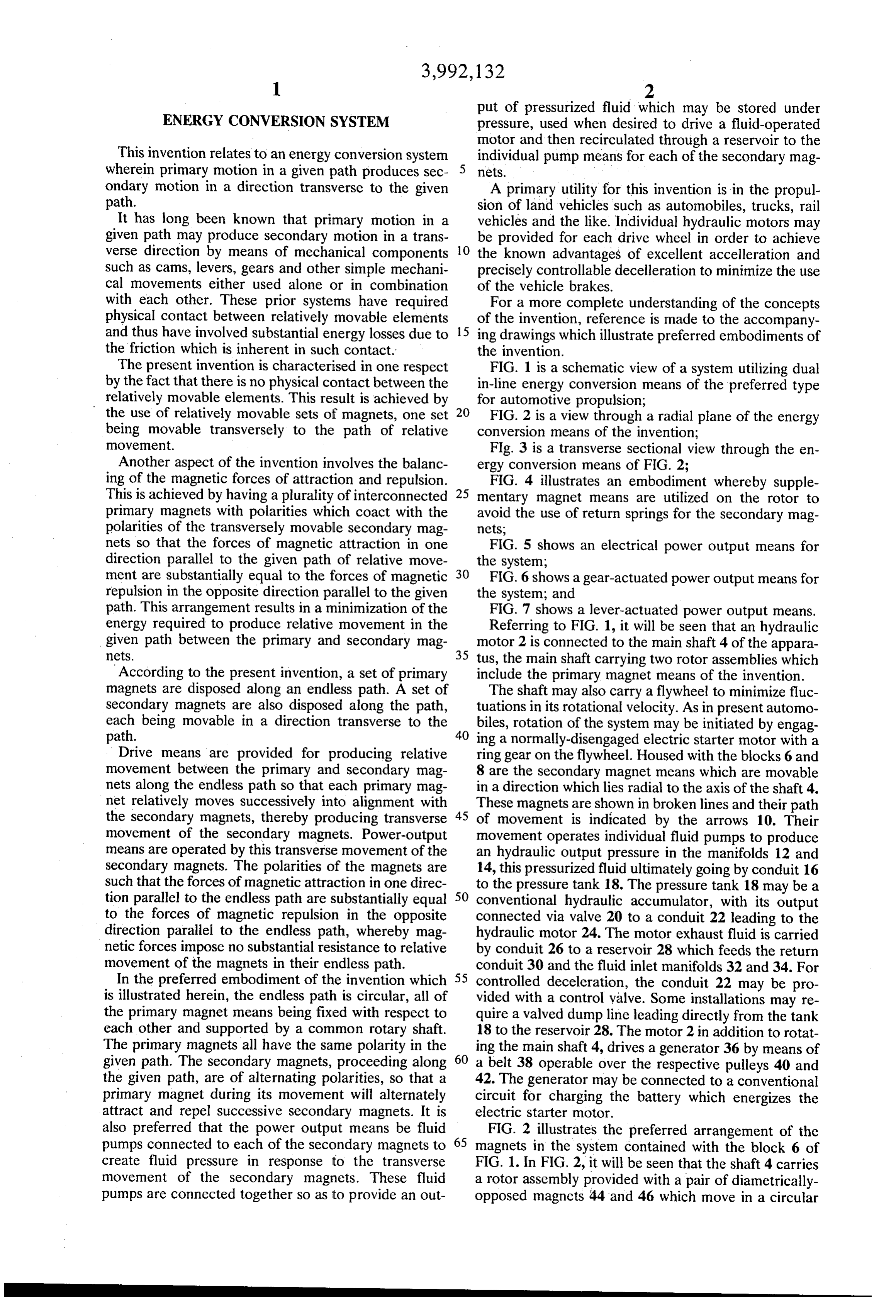
put of pressurized fluid which may be stored under
ENERGY CONVERSION SYSTEM pressure, used when desired to drive a fluid-operated motor and then recirculated through a reservoir to the
This invention relates to an energy conversion system individual pump means for each of the secondary mag wherein primary motion in a given path produces sec netS.
ondary motion in a direction transverse to the given A primary utility for this invention is in the propul path. sion of land vehicles such as automobiles, trucks, rail It has long been known that primary motion in a vehicles and the like. Individual hydraulic motors may given path may produce secondary motion in a trans be provided for each drive wheel in order to achieve verse direction by means of mechanical components 10 the known advantages of excellent accelleration and such as cams, levers, gears and other simple mechani precisely controllable decelleration to minimize the use cal movements either used alone or in combination of the vehicle brakes.
with each other. These prior systems have required For a more complete understanding of the concepts physical contact between relatively movable elements of the invention, reference is made to the accompany and thus have involved substantial energy losses due to 15 ing drawings which illustrate preferred embodiments of the friction which is inherent in such contact. the invention.
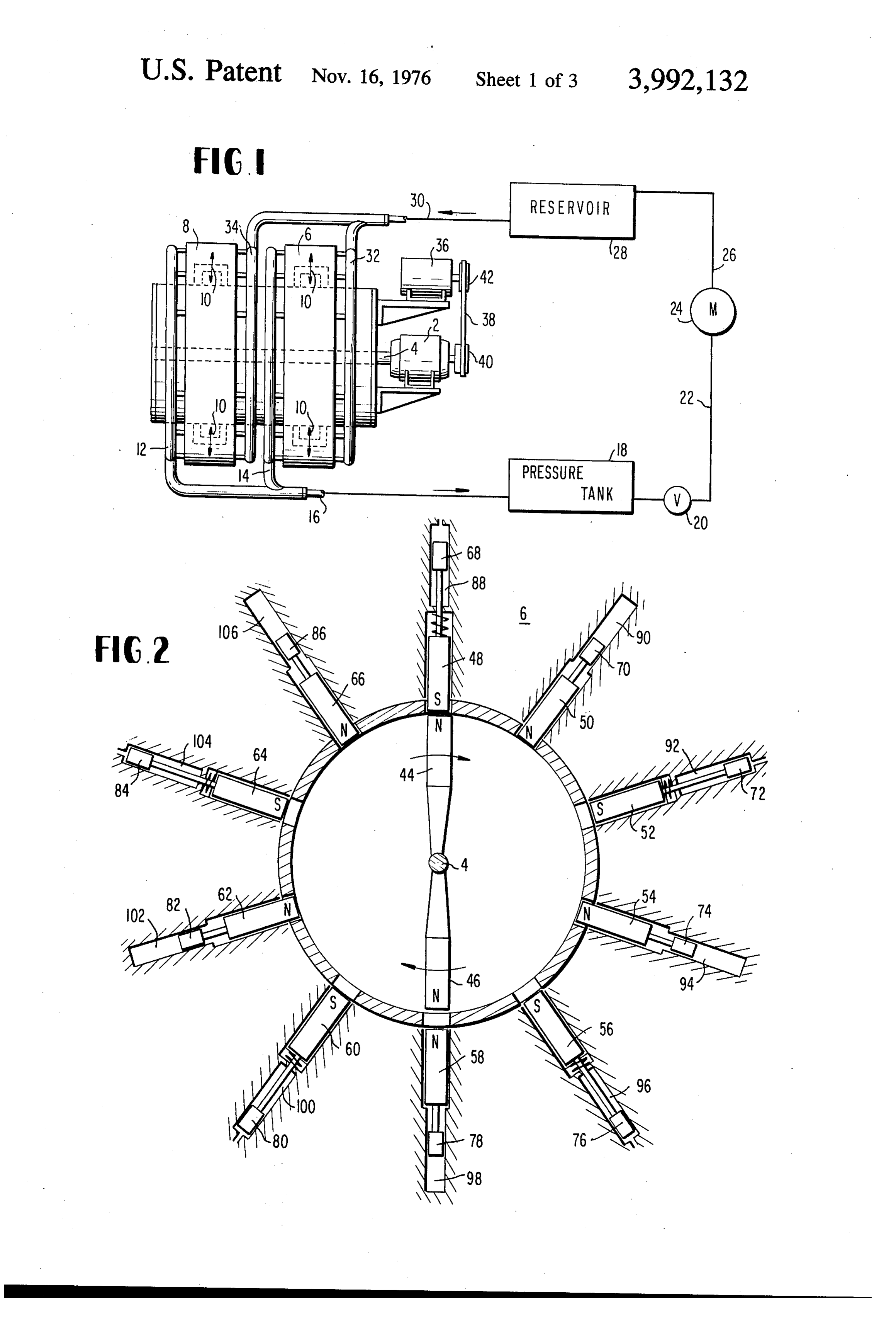
The present invention is characterised in one respect FIG. 1 is a schematic view of a system utilizing dual by the fact that there is no physical contact between the in-line energy conversion means of the preferred type relatively movable elements. This result is achieved by for automotive propulsion;
the use of relatively movable sets of magnets, one set 20 FIG. 2 is a view through a radial plane of the energy being movable transversely to the path of relative conversion means of the invention;
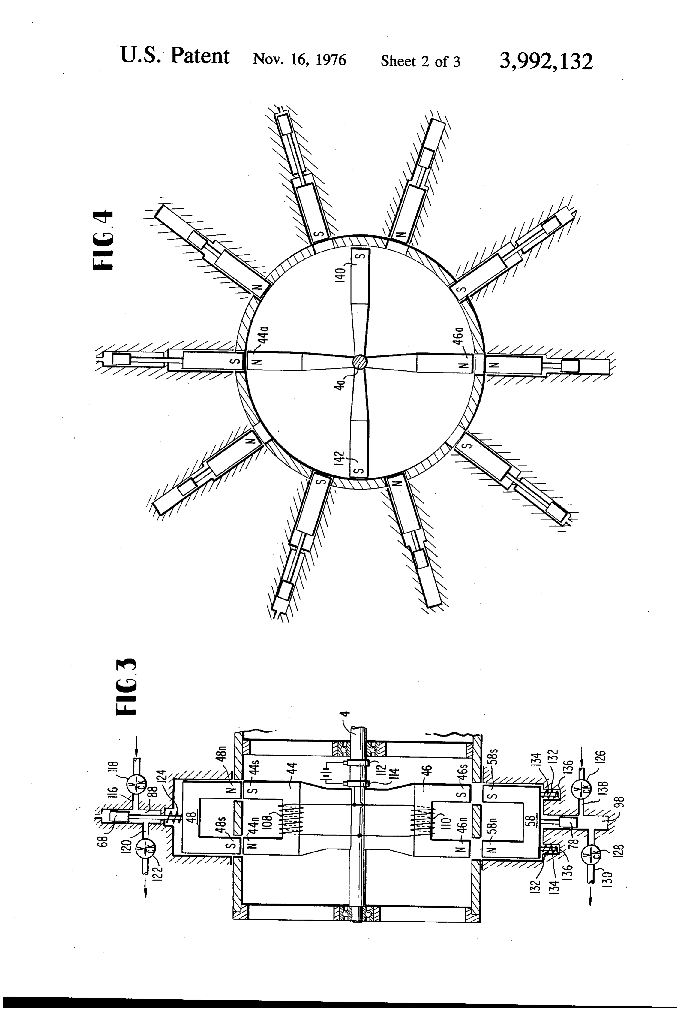
movement. Fig. 3 is a transverse sectional view through the en Another aspect of the invention involves the balanc ergy conversion means of FIG. 2;
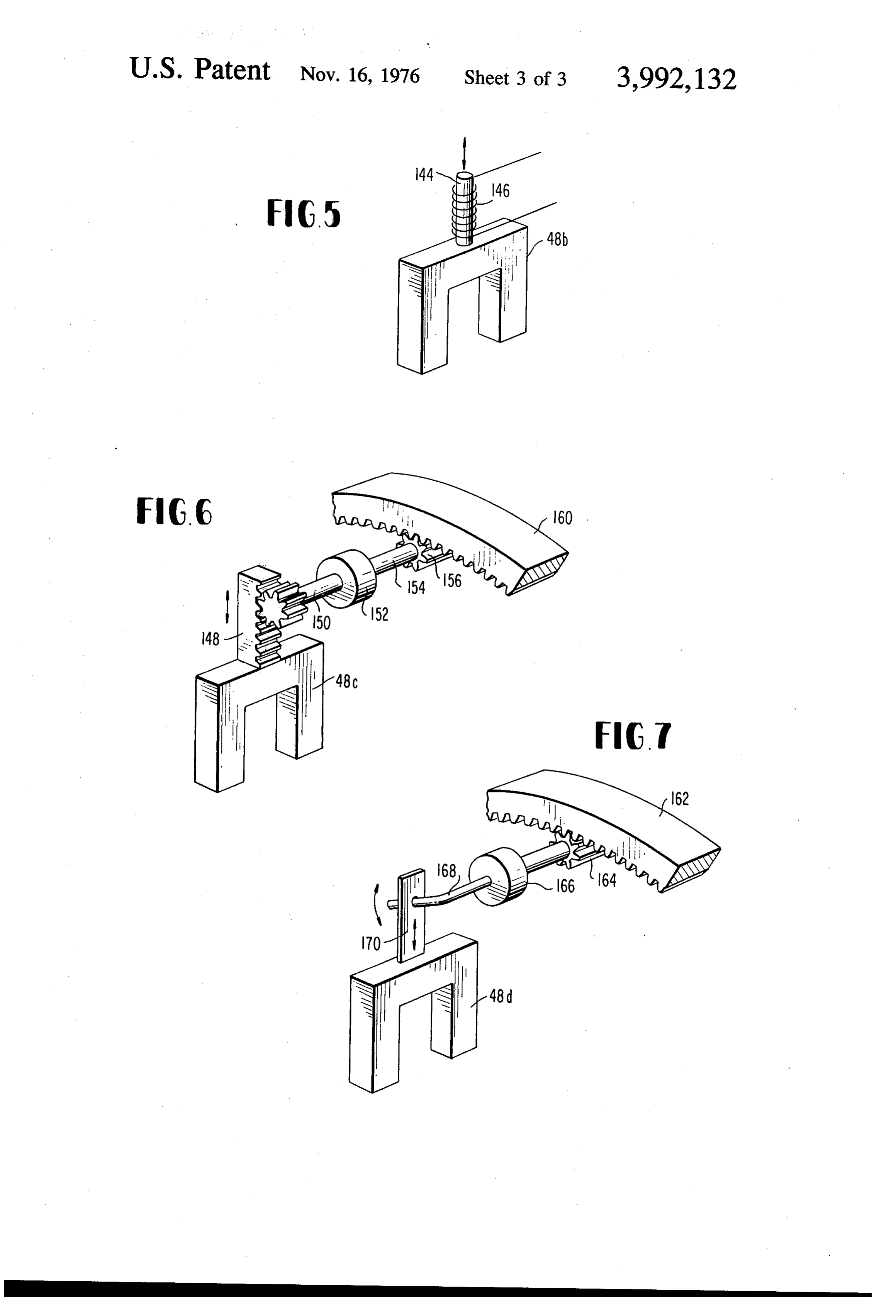
ing of the magnetic forces of attraction and repulsion. FIG. 4 illustrates an embodiment whereby supple This is achieved by having a plurality of interconnected 25 mentary magnet means are utilized on the rotor to primary magnets with polarities which coact with the avoid the use of return springs for the secondary mag polarities of the transversely movable secondary mag nets, nets so that the forces of magnetic attraction in one FIG. 5 shows an electrical power output means for direction parallel to the given path of relative move the system;
ment are substantially equal to the forces of magnetic 30 FIG. 6 shows a gear-actuated power output means for repulsion in the opposite direction parallel to the given the system; and path. This arrangement results in a minimization of the FIG. 7 shows a lever-actuated power output means. energy required to produce relative movement in the Referring to FIG. 1, it will be seen that an hydraulic given path between the primary and secondary mag motor 2 is connected to the main shaft 4 of the appara netS. 35 tus, the main shaft carrying two rotor assemblies which According to the present invention, a set of primary include the primary magnet means of the invention. magnets are disposed along an endless path. A set of The shaft may also carry a flywheel to minimize fluc secondary magnets are also disposed along the path, tuations in its rotational velocity. As in present automo each being movable in a direction transverse to the 40 biles, rotation of the system may be initiated by engag path. ing a normally-disengaged electric starter motor with a Drive means are provided for producing relative ring gear on the flywheel. Housed with the blocks 6 and movement between the primary and secondary mag 8 are the secondary magnet means which are movable nets along the endless path so that each primary mag in a direction which lies radial to the axis of the shaft 4. net relatively moves successively into alignment with These magnets are shown in broken lines and their path the secondary magnets, thereby producing transverse 45 of movement is indicated by the arrows 10. Their movement of the secondary magnets. Power-output movement operates individual fluid pumps to produce means are operated by this transverse movement of the an hydraulic output pressure in the manifolds 12 and secondary magnets. The polarities of the magnets are 14, this pressurized fluid ultimately going by conduit 16 such that the forces of magnetic attraction in one direc to the pressure tank 18. The pressure tank 18 may be a tion parallel to the endless path are substantially equal 50 conventional hydraulic accumulator, with its output to the forces of magnetic repulsion in the opposite direction parallel to the endless path, whereby mag connected via valve 20 to a conduit 22 leading to the hydraulic motor 24. The motor exhaust fluid is carried netic forces impose no substantial resistance to relative by conduit 26 to a reservoir 28 which feeds the return movement of the magnets in their endless path. conduit 30 and the fluid inlet manifolds 32 and 34. For In the preferred embodiment of the invention which 55 controlled deceleration, the conduit 22 may be pro is illustrated herein, the endless path is circular, all of vided with a control valve. Some installations may re the primary magnet means being fixed with respect to quire a valved dump line leading directly from the tank each other and supported by a common rotary shaft. 18 to the reservoir 28. The motor 2 in addition to rotat The primary magnets all have the same polarity in the ing the main shaft 4, drives a generator 36 by means of given path. The secondary magnets, proceeding along 60 a belt 38 operable over the respective pulleys 40 and the given path, are of alternating polarities, so that a 42. The generator may be connected to a conventional primary magnet during its movement will alternately circuit for charging the battery which energizes the attract and repel successive secondary magnets. It is electric starter motor.
also preferred that the power output means be fluid FIG. 2 illustrates the preferred arrangement of the pumps connected to each of the secondary magnets to 65 magnets in the system contained with the block 6 of create fluid pressure in response to the transverse FIG. 1. In FIG. 2, it will be seen that the shaft 4 carries movement of the secondary magnets. These fluid a rotor assembly provided with a pair of diametrically pumps are connected together so as to provide an out opposed magnets 44 and 46 which move in a circular
Page 6
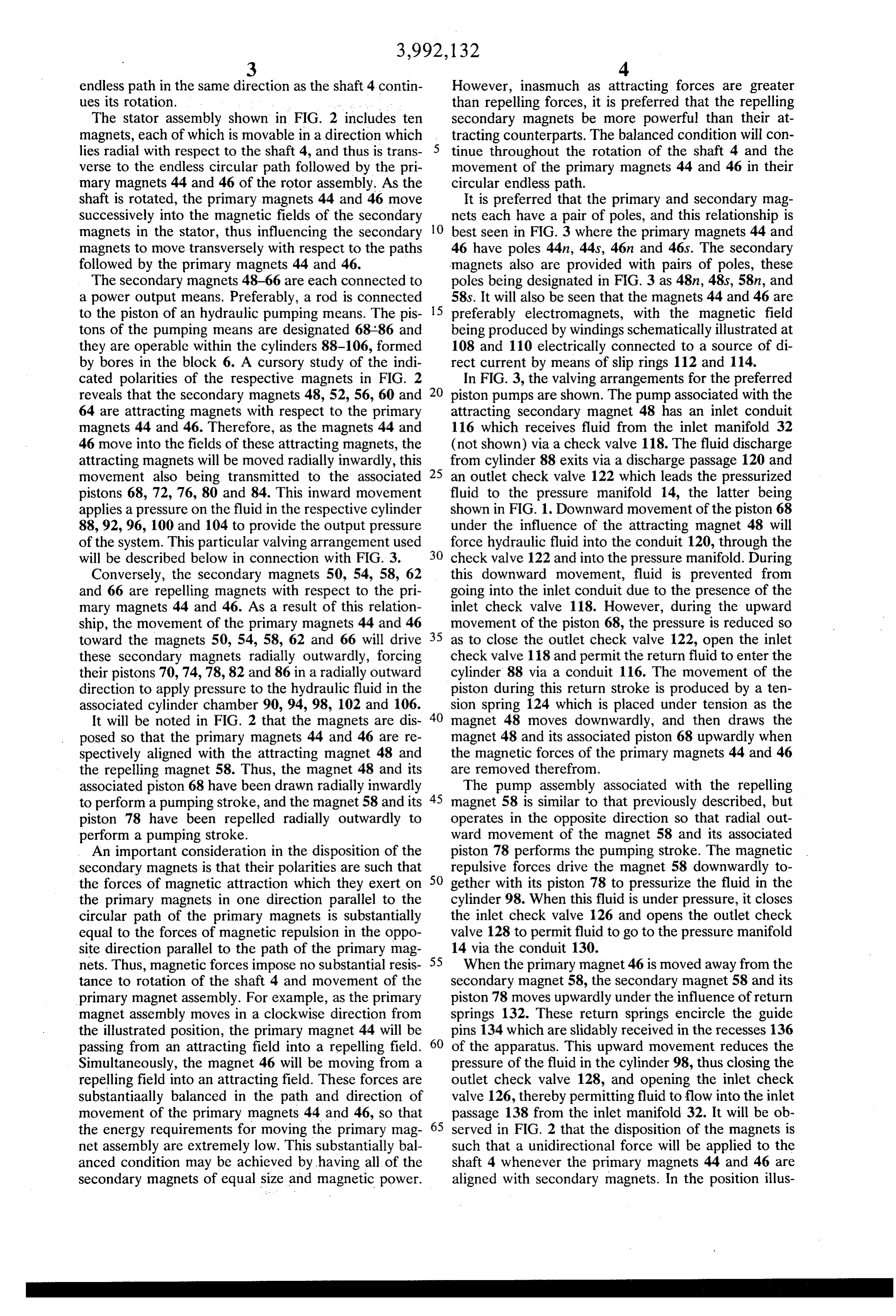
endless path in the same direction as the shaft 4 contin However, inasmuch as attracting forces are greater ues its rotation. than repelling forces, it is preferred that the repelling The stator assembly shown in FIG. 2 includes ten secondary magnets be more powerful than their at magnets, each of which is movable in a direction which tracting counterparts. The balanced condition will con lies radial with respect to the shaft 4, and thus is trans tinue throughout the rotation of the shaft 4 and the verse to the endless circular path followed by the pri movement of the primary magnets 44 and 46 in their mary magnets 44 and 46 of the rotor assembly. As the circular endless path.
shaft is rotated, the primary magnets 44 and 46 move It is preferred that the primary and secondary mag successively into the magnetic fields of the secondary nets each have a pair of poles, and this relationship is magnets in the stator, thus influencing the secondary 10 best seen in FIG. 3 where the primary magnets 44 and magnets to move transversely with respect to the paths 46 have poles 44n, 44s, 46.n and 46s. The secondary followed by the primary magnets 44 and 46. magnets also are provided with pairs of poles, these The secondary magnets 48-66 are each connected to poles being designated in FIG. 3 as 48n, 48s, 58n, and a power output means. Preferably, a rod is connected 58s. It will also be seen that the magnets 44 and 46 are to the piston of an hydraulic pumping means. The pis 15 preferably electromagnets, with the magnetic field tons of the pumping means are designated 68 86 and being produced by windings schematically illustrated at they are operable within the cylinders 88-106, formed 108 and 110 electrically connected to a source of di by bores in the block 6. A cursory study of the indi rect current by means of slip rings 112 and 114. cated polarities of the respective magnets in FIG. 2 In FIG. 3, the valving arrangements for the preferred reveals that the secondary magnets 48, 52, 56, 60 and 20 piston pumps are shown. The pump associated with the 64 are attracting magnets with respect to the primary attracting secondary magnet 48 has an inlet conduit magnets 44 and 46. Therefore, as the magnets 44 and 116 which receives fluid from the inlet manifold 32 46 move into the fields of these attracting magnets, the (not shown) via a check valve 118. The fluid discharge attracting magnets will be moved radially inwardly, this from cylinder 88 exits via a discharge passage 120 and movement also being transmitted to the associated 25 an outlet check valve 122 which leads the pressurized pistons 68, 72, 76, 80 and 84. This inward movement fluid to the pressure manifold 14, the latter being applies a pressure on the fluid in the respective cylinder shown in FIG. 1. Downward movement of the piston 68 88, 92, 96, 100 and 104 to provide the output pressure under the influence of the attracting magnet 48 will of the system. This particular valving arrangement used force hydraulic fluid into the conduit 120, through the will be described below in connection with FIG. 3. 30 check valve 122 and into the pressure manifold. During Conversely, the secondary magnets 50, 54, 58, 62 this downward movement, fluid is prevented from and 66 are repelling magnets with respect to the pri going into the inlet conduit due to the presence of the mary magnets 44 and 46. As a result of this relation inlet check valve 118. However, during the upward ship, the movement of the primary magnets 44 and 46 35 movement of the piston 68, the pressure is reduced so toward the magnets 50, 54, 58, 62 and 66 will drive as to close the outlet check valve 122, open the inlet these secondary magnets radially outwardly, forcing check valve 118 and permit the return fluid to enter the their pistons 70, 74,78, 82 and 86 in a radially outward cylinder 88 via a conduit 116. The movement of the direction to apply pressure to the hydraulic fluid in the piston during this return stroke is produced by a ten associated cylinder chamber 90,94, 98, 102 and 106. 40 sion spring 124 which is placed under tension as the It will be noted in FIG. 2 that the magnets are dis magnet 48 moves downwardly, and then draws the posed so that the primary magnets 44 and 46 are re magnet 48 and its associated piston 68 upwardly when spectively aligned with the attracting magnet 48 and the magnetic forces of the primary magnets 44 and 46 the repelling magnet 58. Thus, the magnet 48 and its are removed therefrom.
associated piston 68 have been drawn radially inwardly The pump assembly associated with the repelling to perform a pumping stroke, and the magnet 58 and its 45 magnet 58 is similar to that previously described, but piston 78 have been repelled radially outwardly to operates in the opposite direction so that radial out perform a pumping stroke. ward movement of the magnet 58 and its associated An important consideration in the disposition of the piston 78 performs the pumping stroke. The magnetic secondary magnets is that their polarities are such that repulsive forces drive the magnet 58 downwardly to the forces of magnetic attraction which they exert on 50 gether with its piston 78 to pressurize the fluid in the the primary magnets in one direction parallel to the cylinder 98. When this fluid is under pressure, it closes circular path of the primary magnets is substantially the inlet check valve 126 and opens the outlet check equal to the forces of magnetic repulsion in the oppo valve 128 to permit fluid to go to the pressure manifold site direction parallel to the path of the primary mag 55 14 via the conduit 130.
nets. Thus, magnetic forces impose no substantial resis When the primary magnet 46 is moved away from the tance to rotation of the shaft 4 and movement of the secondary magnet 58, the secondary magnet 58 and its primary magnet assembly. For example, as the primary piston 78 moves upwardly under the influence of return magnet assembly moves in a clockwise direction from springs 132. These return springs encircle the guide the illustrated position, the primary magnet 44 will be pins 134 which are slidably received in the recesses 136 passing from an attracting field into a repelling field. 60 of the apparatus. This upward movement reduces the Simultaneously, the magnet 46 will be moving from a pressure of the fluid in the cylinder 98, thus closing the repelling field into an attracting field. These forces are outlet check valve 128, and opening the inlet check substantiaally balanced in the path and direction of valve 126, thereby permitting fluid to flow into the inlet movement of the primary magnets 44 and 46, so that passage 138 from the inlet manifold 32. It will be ob the energy requirements for moving the primary mag 65 served in FIG. 2 that the disposition of the magnets is net assembly are extremely low. This substantially bal such that a unidirectional force will be applied to the anced condition may be achieved by having all of the shaft 4 whenever the primary magnets 44 and 46 are secondary magnets of equal size and magnetic power. aligned with secondary magnets. In the position illus
Page 7
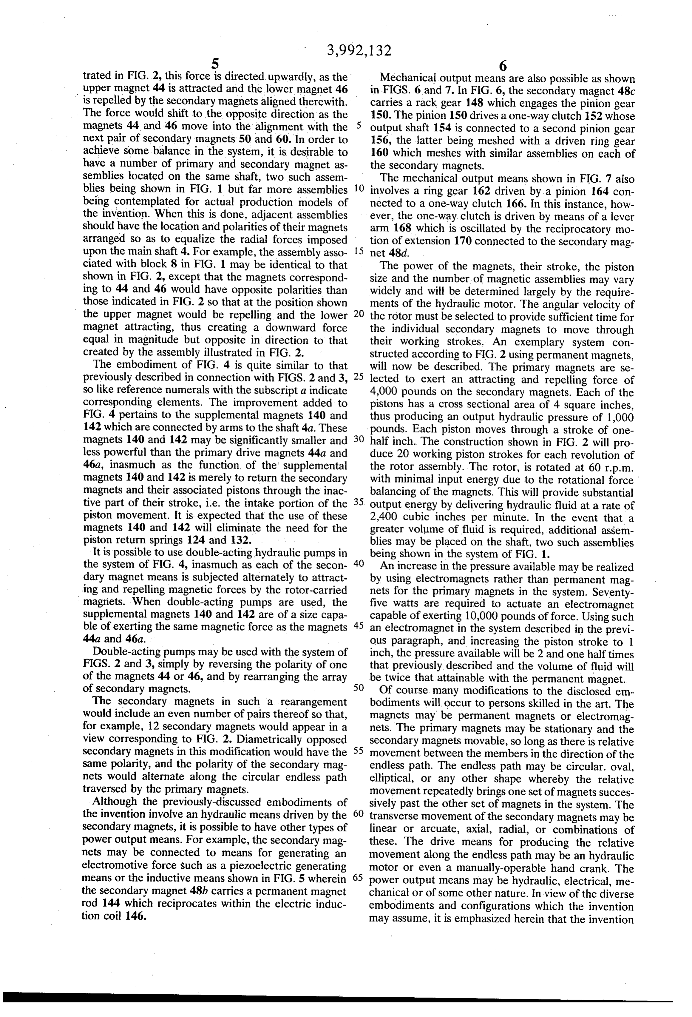
trated in FIG. 2, this force is directed upwardly, as the Mechanical output means are also possible as shown upper magnet 44 is attracted and the lower magnet 46 in FIGS. 6 and 7. In FIG. 6, the secondary magnet 48c is repelled by the secondary magnets aligned therewith. carries a rack gear 148 which engages the pinion gear The force would shift to the opposite direction as the 150. The pinion 150 drives a one-way clutch 152 whose magnets 44 and 46 move into the alignment with the output shaft 154 is connected to a second pinion gear next pair of secondary magnets 50 and 60. In order to 156, the latter being meshed with a driven ring gear achieve some balance in the system, it is desirable to 160 which meshes with similar assemblies on each of have a number of primary and secondary magnet as the secondary magnets.
semblies located on the same shaft, two such assem The mechanical output means shown in FIG. 7 also blies being shown in FIG. 1 but far more assemblies 10 involves a ring gear 162 driven by a pinion 164 con being contemplated for actual production models of nected to a one-way clutch 166. In this instance, how the invention. When this is done, adjacent assemblies ever, the one-way clutch is driven by means of a lever should have the location and polarities of their magnets arm 168 which is oscillated by the reciprocatory mo arranged so as to equalize the radial forces imposed tion of extension 170 connected to the secondary mag upon the main shaft 4. For example, the assembly asso 15 net 48d.
ciated with block 8 in FIG. 1 may be identical to that The power of the magnets, their stroke, the piston shown in FIG. 2, except that the magnets correspond size and the number of magnetic assemblies may vary ing to 44 and 46 would have opposite polarities than widely and will be determined largely by the require those indicated in FIG. 2 so that at the position shown ments of the hydraulic motor. The angular velocity of the upper magnet would be repelling and the lower 20 the rotor must be selected to provide sufficient time for magnet attracting, thus creating a downward force the individual secondary magnets to move through equal in magnitude but opposite in direction to that their working strokes. An exemplary system con created by the assembly illustrated in FIG. 2. structed according to FIG. 2 using permanent magnets, The embodiment of FIG. 4 is quite similar to that will now be described. The primary magnets are se previously described in connection with FIGS. 2 and 3, 25 lected to exert an attracting and repelling force of so like reference numerals with the subscripta indicate 4,000 pounds on the secondary magnets. Each of the corresponding elements. The improvement added to pistons has a cross sectional area of 4 square inches, FIG. 4 pertains to the supplemental magnets 140 and thus producing an output hydraulic pressure of 1,000 142 which are connected by arms to the shaft 4a. These pounds. Each piston moves through a stroke of one magnets 140 and 142 may be significantly smaller and 30 half inch. The construction shown in FIG. 2 will pro less powerful than the primary drive magnets 44a and duce 20 working piston strokes for each revolution of 46a, inasmuch as the function of the supplemental the rotor assembly. The rotor, is rotated at 60 r.p.m. magnets 140 and 142 is merely to return the secondary with minimal input energy due to the rotational force magnets and their associated pistons through the inac balancing of the magnets. This will provide substantial tive part of their stroke, i.e. the intake portion of the 35 output energy by delivering hydraulic fluid at a rate of piston movement. It is expected that the use of these 2,400 cubic inches per minute. In the event that a magnets 140 and 142 will eliminate the need for the greater volume of fluid is required, additional assem piston return springs 124 and 132. blies may be placed on the shaft, two such assemblies It is possible to use double-acting hydraulic pumps in being shown in the system of FIG. 1. the system of FIG. 4, inasmuch as each of the secon 40 An increase in the pressure available may be realized dary magnet means is subjected alternately to attract by using electromagnets rather than permanent mag ing and repelling magnetic forces by the rotor-carried nets for the primary magnets in the system. Seventy magnets. When double-acting pumps are used, the five watts are required to actuate an electromagnet supplemental magnets 140 and 142 are of a size capa capable of exerting 10,000 pounds of force. Using such ble of exerting the same magnetic force as the magnets 45 an electromagnet in the system described in the previ 44a and 46a. ous paragraph, and increasing the piston stroke to 1 Double-acting pumps may be used with the system of inch, the pressure available will be 2 and one halftimes FIGS. 2 and 3, simply by reversing the polarity of one that previously described and the volume of fluid will of the magnets 44 or 46, and by rearranging the array be twice that attainable with the permanent magnet.
Of course many modifications to the disclosed em
The secondary magnets in such a rearangement bodiments will occur to persons skilled in the art. The would include an even number of pairs thereof so that, magnets may be permanent magnets or electromag for example, 12 secondary magnets would appear in a nets. The primary magnets may be stationary and the view corresponding to FIG. 2. Diametrically opposed secondary magnets movable, so long as there is relative secondary magnets in this modification would have the 55 movement between the members in the direction of the same polarity, and the polarity of the secondary mag endless path. The endless path may be circular. oval, nets would alternate along the circular endless path elliptical, or any other shape whereby the relative traversed by the primary magnets. movement repeatedly brings one set of magnets succes Although the previously-discussed embodiments of sively past the other set of magnets in the system. The the invention involve an hydraulic means driven by the 60 transverse movement of the secondary magnets may be secondary magnets, it is possible to have other types of linear or arcuate, axial, radial, or combinations of power output means. For example, the secondary mag these. The drive means for producing the relative nets may be connected to means for generating an movement along the endless path may be an hydraulic electromotive force such as a piezoelectric generating motor or even a manually-operable hand crank. The means or the inductive means shown in FIG. 5 wherein 65 power output means may be hydraulic, electrical, me the secondary magnet 48b carries a permanent magnet chanical or of some other nature. In view of the diverse rod 144 which reciprocates within the electric induc embodiments and configurations which the invention tion coil 146. may assume, it is emphasized herein that the invention
Page 8
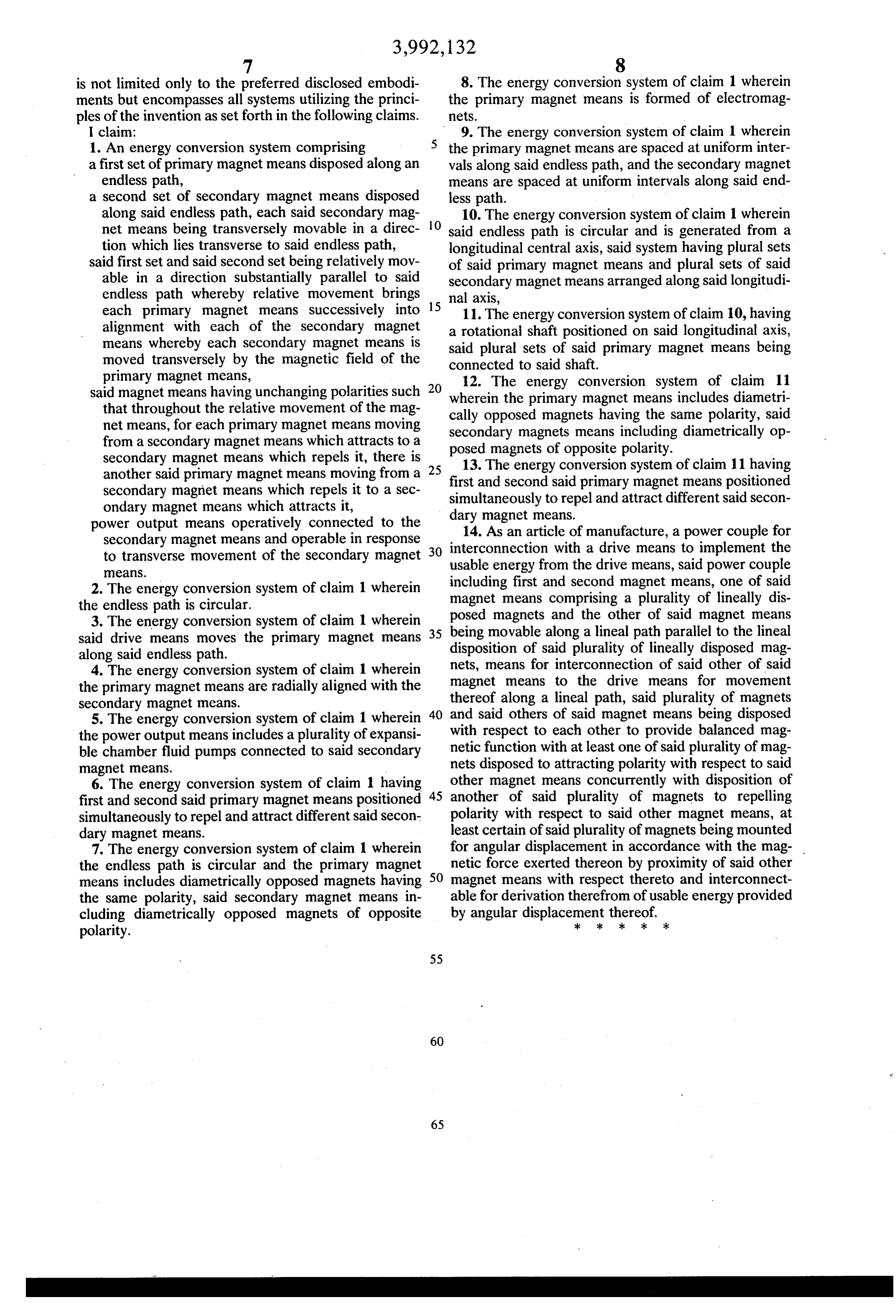
is not limited only to the preferred disclosed embodi 8. The energy conversion system of claim 1 wherein ments but encompasses all systems utilizing the princi the primary magnet means is formed of electromag ples of the invention as set forth in the following claims. netS.
I claim: 9. The energy conversion system of claim 1 wherein 1. An energy conversion system comprising the primary magnet means are spaced at uniform inter a first set of primary magnet means disposed along an vals along said endless path, and the secondary magnet endless path, means are spaced at uniform intervals along said end a second set of secondary magnet means disposed less path.
along said endless path, each said secondary mag O 10. The energy conversion system of claim 1 wherein net means being transversely movable in a direc said endless path is circular and is generated from a tion which lies transverse to said endless path, longitudinal central axis, said system having plural sets said first set and said second set being relatively mov of said primary magnet means and plural sets of said able in a direction substantially parallel to said secondary magnet means arranged along said longitudi endless path whereby relative movement brings each primary magnet means successively into 15 nal11.axis, The energy conversion system of claim 10, having alignment with each of the secondary magnet a rotational shaft positioned on said longitudinal axis, means whereby each secondary magnet means is said plural sets of said primary magnet means being moved transversely by the magnetic field of the connected to said shaft.
primary magnet means, 12. The energy conversion system of claim 11 said magnet means having unchanging polarities such 20 wherein the primary magnet means includes diametri that throughout the relative movement of the mag cally opposed magnets having the same polarity, said net means, for each primary magnet means moving secondary magnets means including diametrically op from a secondary magnet means which attracts to a posed magnets of opposite secondary magnet means which repels it, there is 25 13. The energy conversionpolarity.
another said primary magnet means moving from a first and second said primary system magnet of claim 11 having means positioned secondary magnet means which repels it to a sec simultaneously to repel and attract different said secon ondary magnet means which attracts it, dary magnet means.
power output means operatively connected to the 14. As an article of manufacture, a power couple for secondary magnet means and operable in response interconnection with a drive means to implement the
to transverse movement of the secondary magnet usable energy from eaS. the drive means, said power couple 2. The energy conversion system of claim 1 wherein magnet means comprising magnet including first and second
means, one of said plurality of lineally dis the endless path is circular. posed magnets and the other of said magnet means 3. The energy conversion system of claim 1 wherein 35 being movable along a lineal path parallel to the lineal said drive means moves the primary magnet means disposition of said plurality of lineally disposed mag along said endless path.
4. The energy conversion system of claim 1 wherein nets, means for interconnection of said other of said the primary magnet means are radially aligned with the magnet means to the drive means for movement secondary magnet means. thereof along a lineal path, said plurality of magnets 5. The energy conversion system of claim 1 wherein 40 and said others of said magnet means being disposed the power output means includes a plurality of expansi with respect to each other to provide balanced mag ble chamber fluid pumps connected to said secondary netic function with at least one of said plurality of mag nets disposed to attracting polarity with respect to said magnet means.
6. The energy conversion system of claim 1 having other magnet means concurrently with disposition of first and second said primary magnet means positioned 45 another of said plurality of magnets to repelling simultaneously to repel and attract different said secon polarity with respect to said other magnet means, at dary magnet means. least certain of said plurality of magnets being mounted 7. The energy conversion system of claim 1 wherein for angular displacement in accordance with the mag the endless path is circular and the primary magnet netic force exerted thereon by proximity of said other means includes diametrically opposed magnets having 50 magnet means with respect thereto and interconnect the same polarity, said secondary magnet means in able for derivation therefrom of usable energy provided cluding diametrically opposed magnets of opposite by angular displacement thereof. polarity. k sk ck k :
Provenance
- Collection
- Cited prior art
- Original PDF
- patentimages.storage.googleapis.com →
- Filed
- 1975-02-04
- Pages
- 8
- Method
- pdftotext (the PDF's own text layer) + pdftoppm 300dpi page scans
- Source
- Google Patents bibliographic record
- Granted
- 1976-11-16
- Inventors
- J. William Putt
- Transcribed from
- patentimages.storage.googleapis.com →