patent · US4361474
Electrolysis chamber for hybrid fuel system
30 November 1982
Page 1 — bibliographic record
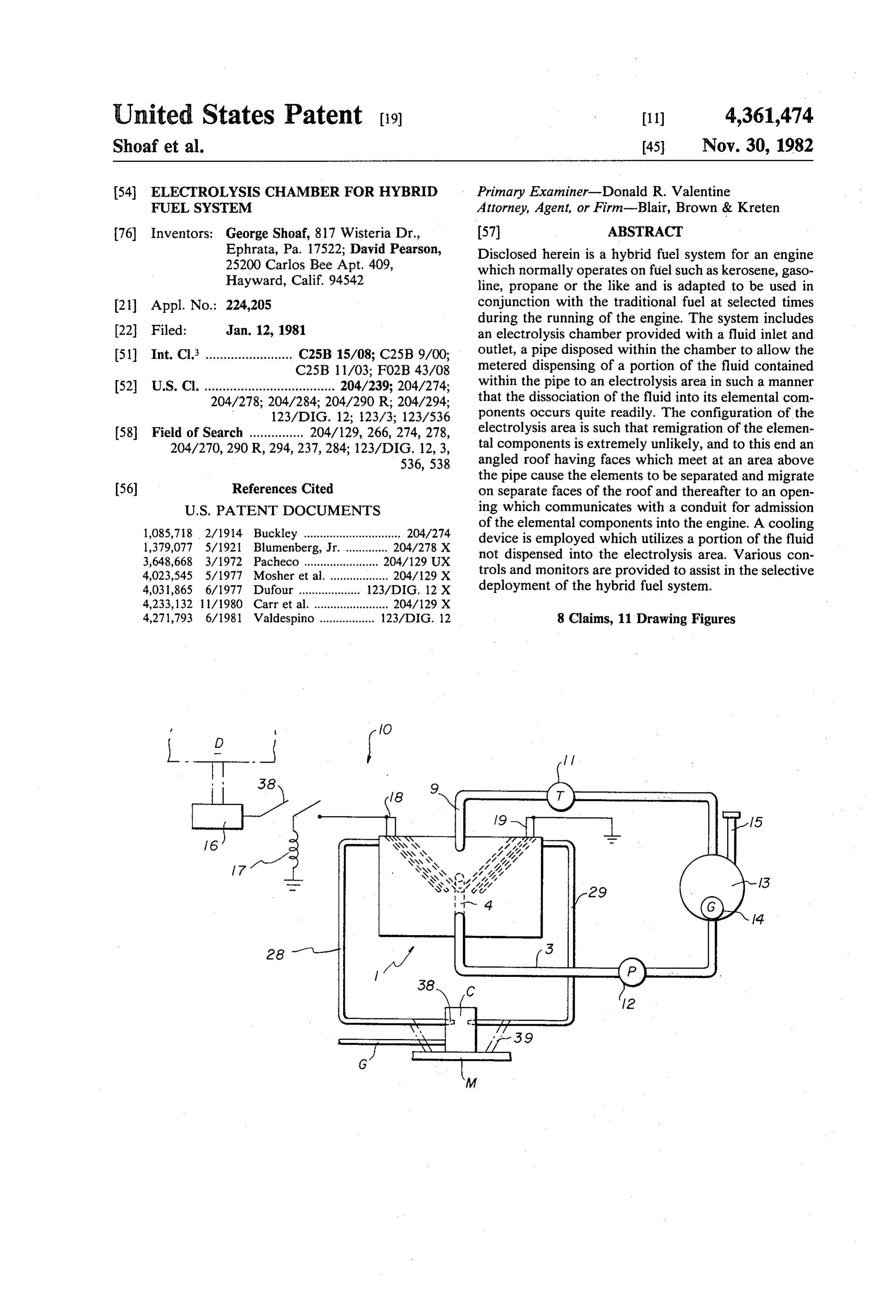
United States Patent (19) 11) 4,361,474 Shoaf et al. 45 Nov.30, 1982 54 ELECTROLYSIS CHAMBER FOR HYBRID Primary Examiner-Donald R. Valentine FUEL SYSTEM Attorney, Agent, or Firm-Blair, Brown & Kreten 76) Inventors: George Shoaf, 817 Wisteria Dr., (57) ABSTRACT Ephrata, Pa. 17522; David Pearson, Disclosed herein is a hybrid fuel system for an engine 25200 Carlos Bee Apt. 409, which normally operates on fuel such as kerosene, gaso Hayward, Calif. 94542 line, propane or the like and is adapted to be used in 21 Appl. No.: 224,205 conjunction with the traditional fuel at selected times during the running of the engine. The system includes 22 Fied: Jan. 12, 1981 an electrolysis chamber provided with a fluid inlet and 51 Int. Cl. ........................ C25B 15/08; C25B 9/00; outlet, a pipe disposed within the chamber to allow the C25B 11/03; FO2B 43/08 metered dispensing of a portion of the fluid contained (52) U.S. Cl. .................................... 204/239; 204/274; within the pipe to an electrolysis area in such a manner 204/278; 204/284; 204/290 R; 204/294; that the dissociation of the fluid into its elemental com 123/DIG. 12; 123/3; 123/536 ponents occurs quite readily. The configuration of the 58 Field of Search ............... 204/129, 266, 274, 278, electrolysis area is such that remigration of the elemen 204/270, 290 R, 294, 237,284; 123/DIG. 12, 3, tal components is extremely unlikely, and to this end an 536,538 angled roof having faces which meet at an area above the pipe cause the elements to be separated and migrate (56) References Cited on separate faces of the roof and thereafter to an open
1,085,718 2/1914 Buckley .............................. 204/274 of the elemental components into the engine. A cooling 1,379,077 5/1921 Blumenberg, Jr. ............. 2O4/278 X device is employed which utilizes a portion of the fluid 3,648,668 3/1972 Pacheco ............. ... 204/129 UX not dispensed into the electrolysis area. Various con 4,023,545 5/1977 Mosher et al. .................. 2O4/29 X trols and monitors are provided to assist in the selective 4,031,865 6/1977 Dufour ........... 123/DIG. 12 X deployment of the hybrid fuel system. 4,233,132 11/1980 Carr et al. ....................... 204/129 X 4,271,793 6/1981 Valdespino ................. 123/DIG. 12 8 Claims, 11 Drawing Figures
Page 2
Drawing sheet — no readable text.
Page 3
Drawing sheet — no readable text.
Page 4
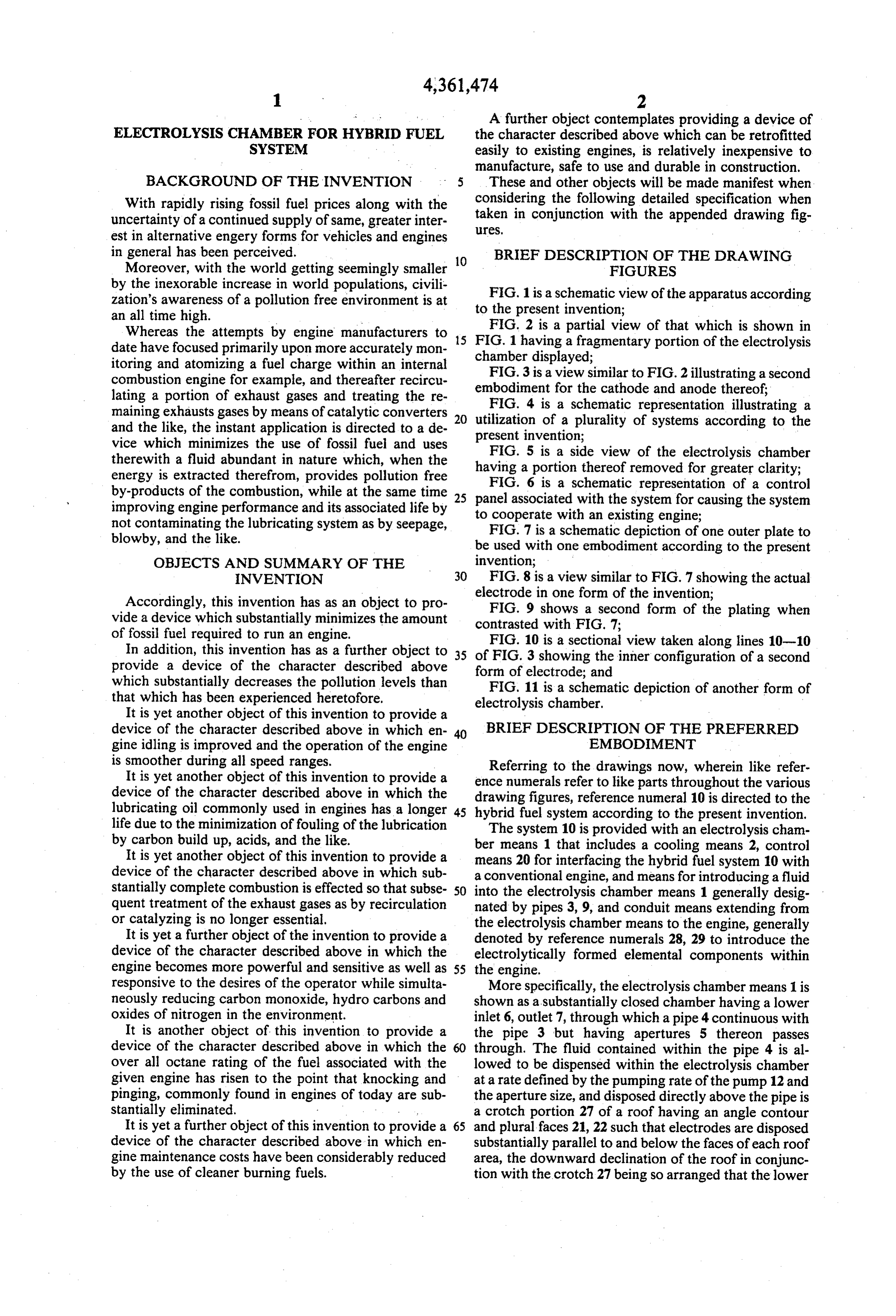
A further object contemplates providing a device of
ELECTROLYSS CHAMBER FOR HYBRD FUEL the character described above which can be retrofitted SYSTEM easily to existing engines, is relatively inexpensive to manufacture, safe to use and durable in construction.
BACKGROUND OF THE INVENTION 5 These and other objects will be made manifest when considering the following detailed specification when
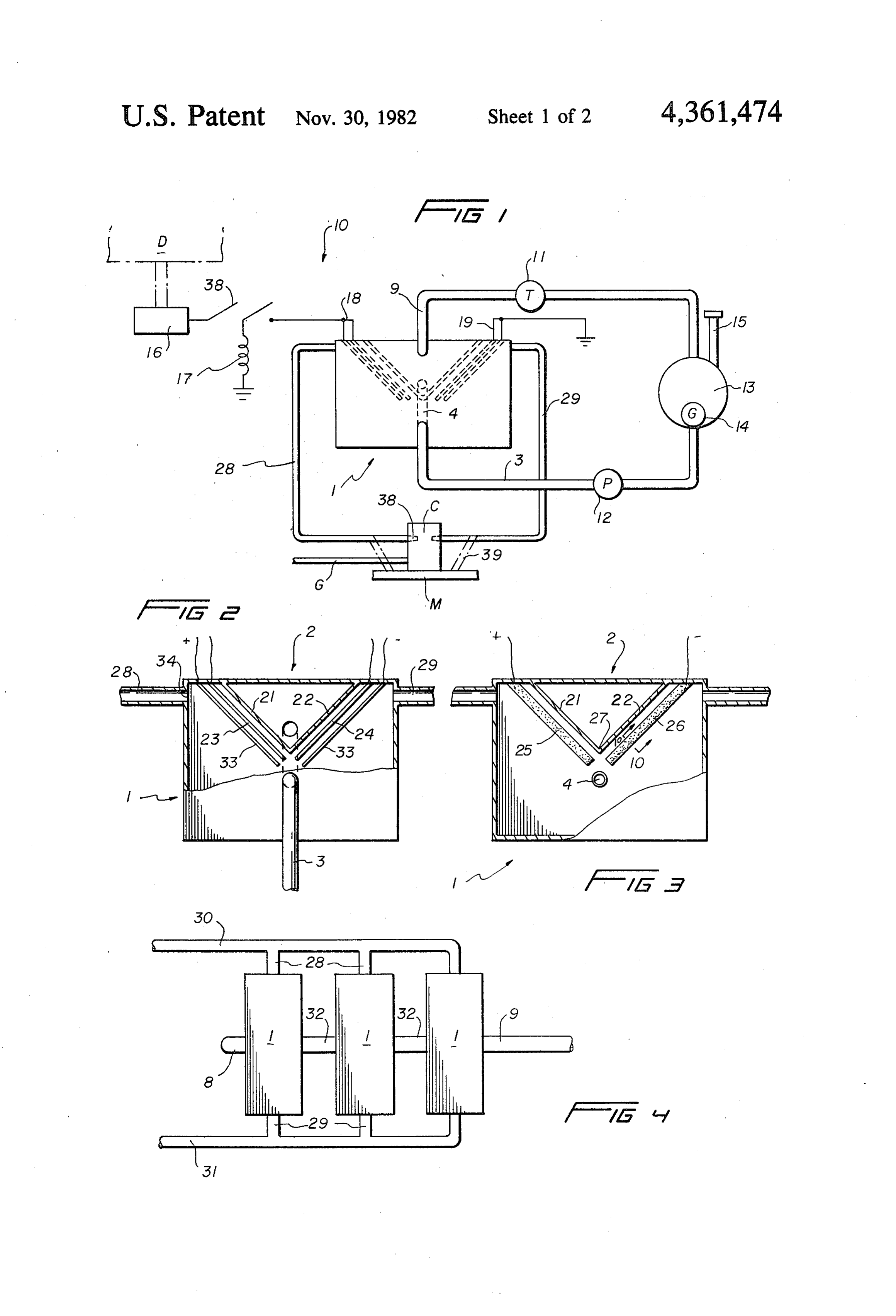
With rapidly rising fossil fuel prices along with the taken uncertainty of a continued supply of same, greater inter leS, in conjunction with the appended drawing fig est in alternative engery forms for vehicles and engines in general has been perceived. BRIEF DESCRIPTION OF THE DRAWING Moreover, with the world getting seemingly smaller 10 FIGURES by the inexorable increase in world populations, civili zation's awareness of a pollution free environment is at to the present invention;view of the apparatus according FIG. 1 is a schematic an all time high.
Whereas the attempts by engine manufacturers to 15 FIG. FIG. 2 is a partial view of that which is shown in date have focused primarily upon more accurately mon chamber 1 having a fragmentary portion of the electrolysis itoring and atomizing a fuel charge within an internal displayed;
FIG.
combustion engine for example, and thereafter recircu embodiment 3 is a view similar to FIG. 2 illustrating a second lating a portion of exhaust gases and treating the re for the cathode and anode thereof; maining exhausts gases by means of catalytic converters 20 utilization ofaa schematic
plurality representation illustrating a of systems according to the and the like, the instant application is directed to a de present invention;
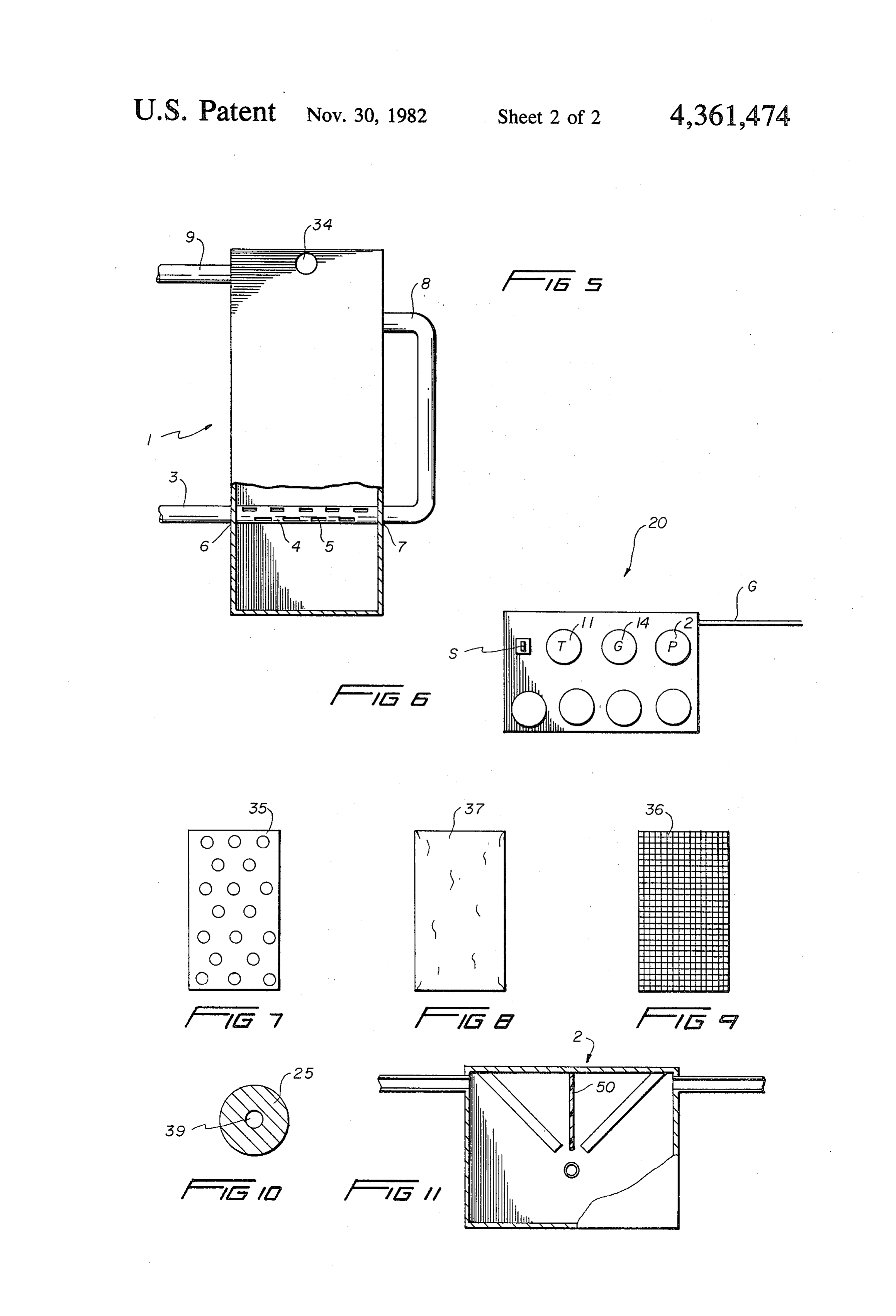
vice which minimizes the use of fossil fuel and uses therewith a fluid abundant in nature which, when the FIG. 5 is a side view of the electrolysis chamber energy is extracted therefrom, provides pollution free having
FIG.
a portion thereof removed for greater clarity;
6 is a schematic representation of a control by-products of the combustion, while at the same time 25 panel associated improving engine performance and its associated life by to cooperate withwith
the system for causing the system existing engine;
not contaminating the lubricating system as by seepage, FIG. 7 is a schematic depiction of one outer plate to blowby, and the like. be used with one embodiment according to the present OBJECTS AND SUMMARY OF THE invention;
INVENTION 30 FIG. 8 is a view similar to FIG. 7 showing the actual Accordingly, this invention has as an object to pro electrode in one form of the invention; vide a device which substantially minimizes the amount contrasted shows
with a second form of the plating when
of fossil fuel required to run an engine. FIG. 10 is a sectional view taken along lines 10-10 In addition, this invention has as a further object to 35 of FIG, 3 showing the inner configuration of a second provide a device of the character described above form of electrode; and which substantially decreases the pollution levels than FIG. 11 is a schematic depiction of another form of that which has been experienced heretofore, electrolysis chamber.
It is yet another object of this invention to provide a device of the character described above in which en 40 BRIEF DESCRIPTION OF THE PREFERRED gine idling is improved and the operation of the engine EMBODIMENT is smoother during all speed ranges. Referring to the drawings now, wherein like refer It is yet another object of this invention to provide a ence numerals refer to like parts throughout the various device of the character described above in which the lubricating oil commonly used in engines has a longer 45 drawing figures, reference numeral 10 is directed to the hybrid fuel system according to the present invention.
life due to the minimization of fouling of the lubrication The system 10 is provided with an electrolysis cham by carbon build up, acids, and the like. ber means 1 that includes a cooling means 2, control It is yet another object of this invention to provide a means 20 for interfacing the hybrid fuel system 10 with device of the character described above in which sub a conventional engine, and means for introducing a fluid stantially complete combustion is effected so that subse 50 into the electrolysis chamber means 1 generally desig quent treatment of the exhaust gases as by recirculation nated by pipes 3, 9, and conduit means extending from or catalyzing is no longer essential. the electrolysis chamber means to the engine, generally It is yet a further object of the invention to provide a denoted by reference numerals 28, 29 to introduce the device of the character described above in which the electrolytically formed elemental components within engine becomes more powerful and sensitive as well as 55 the engine.
responsive to the desires of the operator while simulta More specifically, the electrolysis chamber means 1 is neously reducing carbon monoxide, hydro carbons and shown as a substantially closed chamber having a lower oxides of nitrogen in the environment. inlet 6, outlet 7, through which a pipe 4 continuous with It is another object of this invention to provide a the pipe 3 but having apertures 5 thereon passes device of the character described above in which the through. The fluid contained within the pipe 4 is al over all octane rating of the fuel associated with the lowed to be dispensed within the electrolysis chamber given engine has risen to the point that knocking and at a rate defined by the pumping rate of the pump 12 and pinging, commonly found in engines of today are sub the aperture size, and disposed directly above the pipe is stantially eliminated. . . . a crotch portion 27 of a roof having an angle contour It is yet a further object of this invention to provide a 65 and plural faces 21, 22 such that electrodes are disposed device of the character described above in which en substantially parallel to and below the faces of each roof gine maintenance costs have been considerably reduced area, the downward declination of the roof in conjunc by the use of cleaner burning fuels. tion with the crotch 27 being so arranged that the lower
Page 5
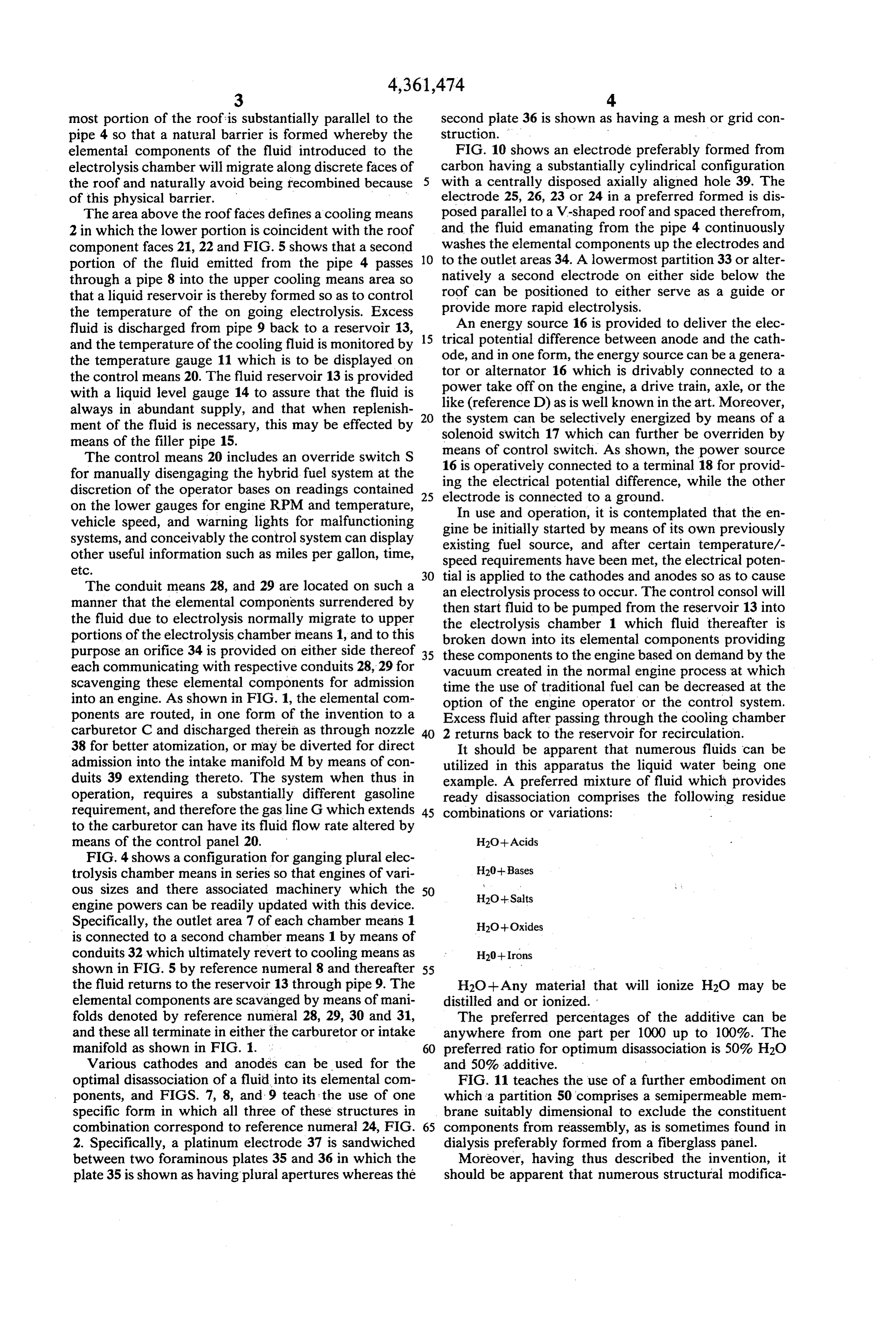
most portion of the roof is substantially parallel to the second plate 36 is shown as having a mesh or grid con pipe 4 so that a natural barrier is formed whereby the struction.
elemental components of the fluid introduced to the FIG. 10 shows an electrode preferably formed from electrolysis chamber will migrate along discrete faces of carbon having a substantially cylindrical configuration the roof and naturally avoid being recombined because 5 with a centrally disposed axially aligned hole 39. The of this physical barrier. electrode 25, 26, 23 or 24 in a preferred formed is dis The area above the roof faces defines a cooling means posed parallel to a V-shaped roof and spaced therefrom, 2 in which the lower portion is coincident with the roof and the fluid emanating from the pipe 4 continuously component faces 21, 22 and FIG. 5 shows that a second 10 washes the elemental components up the electrodes and portion of the fluid emitted from the pipe 4 passes to the outlet areas 34. A lowermost partition 33 or alter through a pipe 8 into the upper cooling means area so natively a second electrode on either side below the roof can be positioned to either serve as a guide or that a liquid reservoir is thereby formed so as to control provide the temperature of the on going electrolysis. Excess more rapid electrolysis. fluid is discharged from pipe 9 back to a reservoir 13, 15 An energy source 16 is provided to deliver the elec and the temperature of the cooling fluid is monitored by trical potential difference between anode and the cath the temperature gauge 11 which is to be displayed on ode, and in one form, the energy source can be a genera the control means 20. The fluid reservoir 13 is provided tor power or alternator 16 which is drivably connected to a take off on the engine, a drive train, axle, or the with a liquid level gauge 14 to assure that the fluid is always in abundant supply, and that when replenish 20 like (reference D) as is well known in the art. Moreover, ment of the fluid is necessary, this may be effected by the system can be selectively energized by means of a means of the filler pipe 15. solenoid switch 17 which can further be overriden by The control means 20 includes an override switch S means of control switch. As shown, the power source for manually disengaging the hybrid fuel system at the 16 isthe operatively connected to a terminal 18 for provid discretion of the operator bases on readings contained 25 ingelectrode electrical potential difference, while the other is connected to a ground.
on the lower gauges for engine RPM and temperature, In use and operation, it is contemplated that the en vehicle speed, and warning lights for malfunctioning gine be initially started by means of its own previously systems, and conceivably the control system can display existing fuel source, and after certain temperature/- other useful information such as miles per gallon, time, speed requirements have been met, the electrical poten etc. 30 tial is applied to the cathodes and anodes so as to cause The conduit means 28, and 29 are located on such a an electrolysis process to occur. The control consol will manner that the elemental components surrendered by then start fluid to be pumped from the reservoir 13 into the fluid due to electrolysis normally migrate to upper the electrolysis chamber 1 which fluid thereafter is portions of the electrolysis chamber means 1, and to this broken down into its elemental components providing purpose an orifice 34 is provided on either side thereof 35 these components to the engine based on demand by the each communicating with respective conduits 28, 29 for vacuum created in the normal engine process at which scavenging these elemental components for admission time the use of traditional fuel can be decreased at the into an engine. As shown in FIG. 1, the elemental come option of the engine operator or the control system. ponents are routed, in one form of the invention to a Excess fluid after passing through the cooling chamber carburetor C and discharged therein as through nozzle 40 2 returns back to the reservoir for recirculation. 38 for better atomization, or may be diverted for direct It should be apparent that numerous fluids can be admission into the intake manifold M by means of con utilized in this apparatus the liquid water being one duits 39 extending thereto. The system when thus in example. A preferred mixture of fluid which provides operation, requires a substantially different gasoline ready disassociation comprises the following residue requirement, and therefore the gas line G which extends 45 combinations or variations:
to the carburetor can have its fluid flow rate altered by means of the control panel 20. H2O+ Acids
FIG. 4 shows a configuration for ganging plural elec trolysis chamber means in series so that engines of vari H20--Bases ous sizes and there associated machinery which the 50 Ho -- Salts engine powers can be readily updated with this device.
Specifically, the outlet area 7 of each chamber means 1 H2O-Oxides is connected to a second chamber means 1 by means of conduits 32 which ultimately revert to cooling means as H20+ Irons shown in FIG. 5 by reference numeral 8 and thereafter 55 the fluid returns to the reservoir 13 through pipe 9. The H2O -- Any material that will ionize H2O may be elemental components are scavanged by means of mani distilled and or ionized.
folds denoted by reference numeral 28, 29, 30 and 31, The preferred percentages of the additive can be and these all terminate in either the carburetor or intake anywhere from one part per 1000 up to 100%. The manifold as shown in FIG. 1. 60 preferred ratio for optimum disassociation is 50% H2O Various cathodes and anodes can be used for the and 50% additive.
optimal disassociation of a fluid into its elemental com FIG. 11 teaches the use of a further embodiment on ponents, and FIGS. 7, 8, and 9 teach the use of one which a partition 50 comprises a semipermeable men specific form in which all three of these structures in brane suitably dimensional to exclude the constituent combination correspond to reference numeral 24, FIG. 65 components from reassembly, as is sometimes found in 2. Specifically, a platinum electrode 37 is sandwiched dialysis preferably formed from a fiberglass panel. between two foraminous plates 35 and 36 in which the Moreover, having thus described the invention, it plate 35 is shown as having plural apertures whereas the should be apparent that numerous structural modifica
Page 6
tions are contemplated as being part of this invention as crotch lower portion of said roof over said pipe serves set forth hereandabove and as defined hereandbelow by as a divider to keep separate said elemental components. the claims. 3. The device of claim 2 wherein said conduit means What is claimed is: gathers said elemental components through conduit 1. A hybrid fuel system for an engine which normally inlets disposed at top areas of said separate faces of said operates on fuel such as gasoline, kerosene, propane or roof whereby said elemental components migrate up the like and to be used in conjunction therewith com wardly along said anode and cathode means into said prising in combination: conduit means.
an electrolysis chamber means including cooling 4. The device of claim 3 wherein said electrolysis means, O chamber means includes energy to disassociate said means for introducing a fluid into said electrolysis fluid into its elemental components said energy is de chamber means for disassociation of said fluid into rived from an alternator operatively connected to said its elemental components, cathode means and anode means and said alternator is and control means for varying the ratio of the fuel to operatively driven.
said elemental components, 15 5. The device of claim 4 wherein said anode and wherein said electrolysis chamber means comprises: a cathode means are formed from carbon tubes. fluid inlet and outlet, a pipe extending through said 6. The device of claim 4 wherein said anode and electrolysis chamber means at said inlet and to said cathode means are formed from a laminate defined by outlet having plural apertures therethrough to foraminous outer plating and a platinum inner foil. allow migration of a first portion of said fluid into 20 7. The device of claim 4 wherein said cooling means an electrolysis area of said electrolysis chamber comprises a fluid reservoir disposed above said roof means from said pipe, a second portion of said fluid filled by said second portion of fluid and discharged to is used as a heat transfer medium for said cooling a storage tank for recirculation through said pipe eaS through an interposed pump.
2. The device of claim 1 wherein said electrolysis area 25 8. The device of claim 4 wherein said fluid comprises is defined by a downwardly angled roof overlying said water and an ionization additive in the preferred ratio pipe having anode and cathode means spaced apart ranges of 50-50 for optimum disassociation. therebelow on separate faces of said roof whereby a 2k k k
Provenance
- Collection
- Cited prior art
- Original PDF
- patentimages.storage.googleapis.com →
- Filed
- 1981-01-12
- Pages
- 6
- Method
- pdftotext (the PDF's own text layer) + pdftoppm 300dpi page scans
- Source
- Google Patents bibliographic record
- Granted
- 1982-11-30
- Inventors
- George Shoaf; David Pearson
- Transcribed from
- patentimages.storage.googleapis.com →