patent · US2006676
Electrolytic carburetor
2 July 1935
Page 1
Drawing sheet — no readable text.
Page 2
Drawing sheet — no readable text.
Page 3
Patented July 2, 1935 2006,676.
UNITED STATES2,006,676.PATENT OFFICE
ELECTROYTC CARBURE OR
. Charles H. Garrett, Dallas, Tex.
Application July 1, 1932, Serial No. 620,364
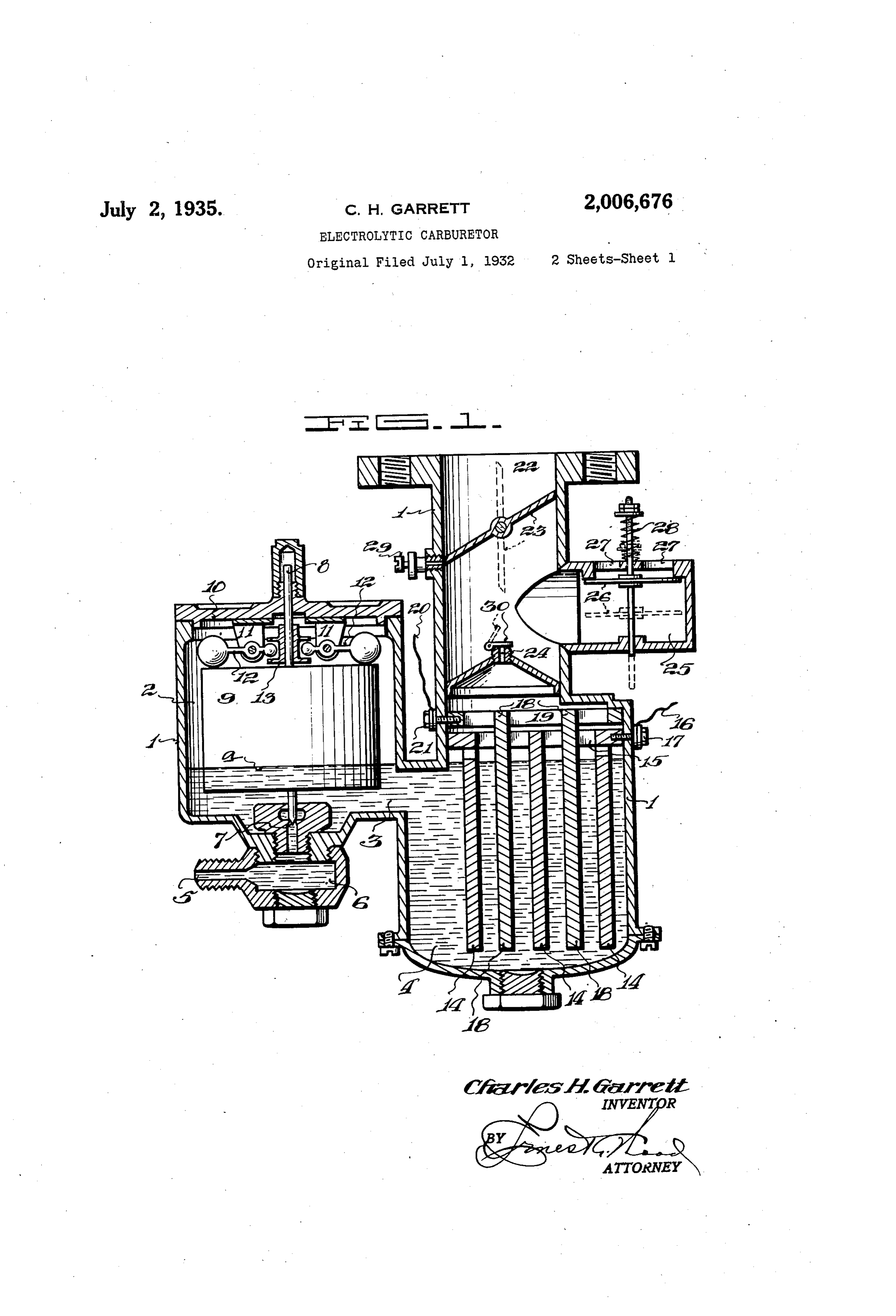
This invention relates to carburetors and it has buretor through an opening 5 which communi cates with the float chamber 2 through the me particular reference to an electrolytic carburetor dium by means of which water may be broken up into of the sediment chamber 6 and the needle its hydrogen and oxygen constituents and the 8valve orifice T, which is closed by a needle valve when the device is not in operation. A float 5 gases So formed suitably mixed with air.
The principal object of the invention is to pro 9 surrounds the needle valve 8 and is free to move vide in a device of the character described, a vertically relative thereto. Depending from the mechanism by means of which water may be cover.0 to the float chamber 2 are two ears l, readily decomposed into its constituents, and the located at spaced intervals...on opposite sides of O constituents intimately mixed with each other the needle valve 8. The members f2 are pivoted 10. and with air. to the ears l, as shown. The weighted outer Another object of the invention is to provide ends of the members 2 rest on top of the float means whereby the electrolyte level in the car 9,groove and their inner ends are received in an annular in the collar 3 which is rigidly attached.
buretor may be maintained at a more or less 5 constant level regardless of fluctuations in fluid to the needle valve 8. a 5 pressure at the fluid inlet of the carburetor. Within the gas generating chamber 4, a series Another object of the invention is to provide of spaced, depending plates 4 are suspended from means whereby the relative amount of air mixed . a horizontal member 5 to which a wire f6 has with the hydrogen and oxygen may be regulated electrical contact through the medium of the bolt 20 as desired. 7, which extends inwardly through the housing 20. Still another object of the invention is the pro and is threaded into the horizontal member 5. vision of means to preventioss of hydrogen and A second series of plates 8 is located inter Oxygen gases during periods in which these gases mediate the plates 4 and attached to the hori are not being drawn from the carburetor. zontal member 9, and has electrical contact with 25 25 Still another object of the invention is the the wire 20 through the bolt 2 . . provision of means whereby the hydrogen and A gas passageway 22, in which a butterfly valve 23 is located, communicates with the gas gener oxygen resulting from electrolysis may beformed ating in Separate compartments, and a further object chamber through an orifice 24. An air of the invention is the provision of means to peri inlet chamber 25 has communication with the . 30 odically reverse the direction of current flow and gas passageway 22 above the orifice 24. A down- 30 thereby alternate the evolution of the gases in wardly opening check valve 26 is in control of the openings 27, and is held inoperatively closed the separate mingled.
compartments, to
be later inter by means of light spring 28.
With the foregoing objects as paramount, the An adjustable auxiliary air valve 29 is provided 35 invention has particular reference to its salient in the walf of the gas passageway 22, which air 35 features of construction and arrangement of valve is closed by the butterfly valve 23 when the parts, taken in connection with the accompany butterfly valve is closed, but communicates with ing drawings, wherein:- - the outside air when the butterfly valve is open. Figure 1 is a view in vertical section of one The operation of the device is as follows: . 40 form of carburetor. The chambers, 2 and 4 are first filled to the 40 Figure 2 is a modified form. level a with a solution of weak sulphuric acid or Figure 3 is a diagrammatic view of a pole other electrolyte not changed by the passage of changer, showing its actuating mechanism, and current therethrough, and the opening 5 is con Figure 4 is a wiring. diagram for the modified nected to a tank of water, not shown. 45 form of carburetor shown in Figure 2. The wire f is next connected to the positive 45 Continuing more in detail with the drawings, pole of a storage battery. or other source of di reference is primarily directed to Figure 1 in rect current and the wire 20 to the negative pole. which the reference numeral designates the Since the solution within the carburetor is a con carburetor housing, which is preferably con ductor of electricity, current will flow there 50 structed of bakelite or other suitable insulating through and hydrogen will be given off from the 50 material. The housing f is so designed as to di negative or cathode plates 8 and oxygen from vide the carburetor into a float chamber 2 and the positive or anode plates 4. gas generating chamber 4, connected by a fluid The butterfly valve 23 is opened and the gas ---. passage 3. passageway 22 brought into communication with 55 Water under pressure is forced into the car a partial vacuum. Atmospheric pressure acting 55
Page 4
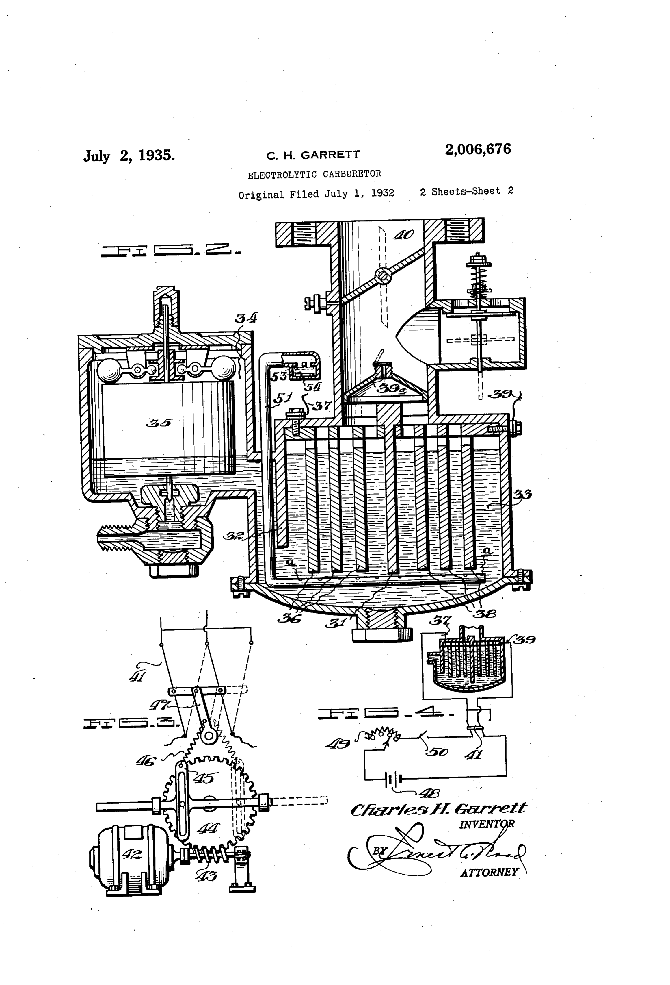
on the top of the check valve 26 causes it to be drives the worm 43 and the gear 4 and causes forced downwardly as shown in dotted lines. The oscillations of the member 45 which is connected hydrogen and oxygen liberated from the water by a spring 46 to the arm 47, thereby causing the at the plates f and 4 are drawn upwardly pole changer to snap from one position to the through the orifice 24 covered by the check valve other.
30 where they are subsequently mixed with air In operation, the carburetor shown in Figure entering through the openings 27 and through the 2 is connected as shown in the wiring diagram auxiliary air valve 29. f of Figure 4. A storage battery 48 or other suit When it is desired to reduce the flow of hydro 10 gen and oxygen from the plates 8 and f4, the able source of direct current is connected to a current flowing through the device is reduced, and variable rhecstat 49, switch 50, pole changer 4 10 to the carburetor as shown. Thus the rate and when the current is interrupted the flow of evolution of the gases can be controlled by the ceases. When the butterfly valve 28 is moved to setting of the rheostat 49 and the desired alter closed position, the check valve 26 is automati 5 cally closed by the spring 28. Any excess gas nate evolution of the gases in the compartments given off during these operations is stored in the theof the carburetor is accomplished by means of periodically operated pole changer 4.
space above the fluid where it is ready for sub Manifestly, the construction shown is capable Sequent use. of considerable modification and such modifica Water is converted into its gaseous constit 20 uents by the device herein described, but the tion as is considered within the scope and mean ing of the appended claims is also considered dilute Sulphuric acid or other suitable electrolyte. within the Spirit and intent of the invention. 20 in the carburetor remains unchanged, since it is What is claimed is:
not destroyed by electrolysis, and the parts in 1. An electrolytic carburetor including an an contact therewith are made of bakelite and lead Ode and a cathode, float means to control the 25 or other material not attacked by the electrolyte.
level, of the electrolyte within said carburetor,
The structure shown in Figure 2 is substantial means to mix, the gases resulting from electrol ly the same as that shown in Figure 1 with the ysis with air, and a check valve independent of exception that the modified structure embraces said float means to control ingress of air to said a larger gas generating chamber which is divided 30 by means of an insulating plate 3 and is further carburetor.
provided with a depending baffle plate 32 which 2. cathode An electrolytic carburetor including anode 30 separates the gas generating chamber 33 from and plates, a float actuated valve in con trol of the electrolyte level within said carbu the float chamber 34 in which the float 35 oper retor, means to mix the gases resulting from ates in the same manner as in Figure 1. More electrolysis with air, a check valve in control 35 over, the structure shown in Figure 2 provides of Said means, a second check valve independent a series of spaced depending plates 36 which are Of Said float actuated valve to prevent loss of electrically connected to the wire 37, and a sec gases from Said carburetor.
Ond Series of similar plates 38 which are electri 3. An electrolytic carburetor. for producing cally connected to the wire 39 and are spaced. mixtures of hydrogen, oxygen and air, including 40 apart from the plates. 36 by the insulating plate a Series of Spaced and electrically connected an 3. Gases generated on the surfaces of the plates ode plates partially immersed in the electrolyte 40 36 and 38 pass upward through the orifice 39a within said carburetor, a series of electrically into the gas passageway 40 where they are mixed connected cathode plates spaced between said with air as explained in the description of Fig anode plates, a float operated valve in control 45. lure 1. of the electrolyte level within said carburetor, A pipe 5? bent as shown in Figure 2 passes an air inlet to said carburetor and a check valve 45 downwardly through the housing of the carbu in control of said air inlet.
retor and has a series of spaced apertures a in 4. An electrolytic carburetor for generating 50 its horizontal portion beneath the plates 36 and hydrogen and oxygen gases from water and for 38. An upwardly opening check valve 53 is in mixing the said gases with air, including, an an control of the air inlet 54. When a partial ode and a cathode partially immersed in an elec 50 vacuum exists in the chamber 33, air is drawn in trolyte within said carburetor, float actuated through the opening 54 and subsequently passes means to replace the water consumed whereby to
upwardly through the apertures a. This air tends maintain a constant fluid level within said de vice, means for mixing the said gases with air, to remove any bubbles of gas collecting on the and plates 36 and 38 and also tends to cool the elec 5. aAncheck valve in control of said latter means. 55 electrolytic carburetor including an an trolyte. The check valve 53 automatically closes Ode and a cathode, float actuated means to con When a gas pressure exists within the carburetor trol the level of the electrolyte within said carbu 60 and thereby prevents the electrolyte from being retor, means to mix the gases resulting from forced out of the opening 54. electrolysis with air, a check valve in control of In order to provide for alternate evolution of said latter means and means to periodically re the gases from the plates 36 and 38, a pole changer 4f shown in Figure 3 is provided, which verse retor.
the direction of current through said carbu 65 is actuated periodically by the motor 42 which CHARLES H. GARRET.
Provenance
- Collection
- Cited prior art
- Original PDF
- patentimages.storage.googleapis.com →
- Filed
- 1932-07-01
- Pages
- 4
- Method
- pdftotext (the PDF's own text layer) + pdftoppm 300dpi page scans
- Source
- Google Patents bibliographic record
- Granted
- 1935-07-02
- Inventors
- Charles H Garrett
- Transcribed from
- patentimages.storage.googleapis.com →