patent · US3459953
Energy storage system
5 August 1969
Page 1
Drawing sheet — no readable text.
Page 2
United States Patent Office 3,459,953 Patented Aug. 5, 1969
storage system for use in maintaining a level of water 3,459,953 in the electrolysis unit so that the entire system may be ENERGY STORAGE SYSTEM completely closed.
William L. Hughes and Stanley O. Brauser, Stillwater,
Okla, assignors to Oklahoma State University, Stil CROSS-REFERENCE water, Okla., a corporation of Oklahoma This is an original application and not related to a Filed Mar. 20, 1967, Ser. No. 624,276 pending application.
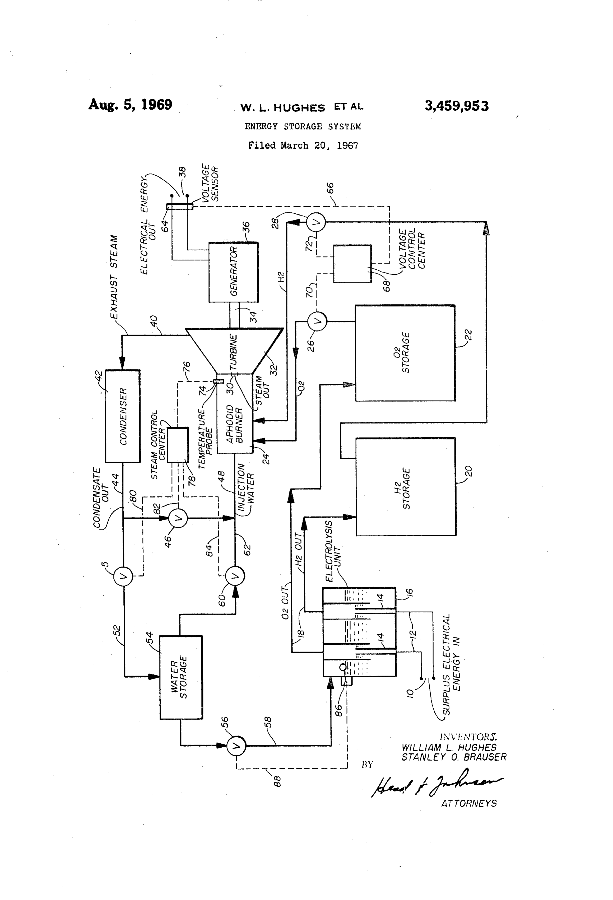
U.S. C. 290-2 8 Claims DESCRIPTION OF VIEWS 0 The drawing is a diagrammatic illustration of the basic
ABSTRACT OF THE DISCLOSURE elements of the energy storage system of this invention. This invention provides a system for storing surplus Gas and liquid lines are shown solid and control con electrical energy and for generating electrical energy from ductors are shown in dotted lines. such stored surplus as conditions require. The system DETAILED DESCRIPTION includes an electrolysis unit wherein surplus electrical energy is utilized to generate hydrogen and oxygen from. fed to the system at energy
Surplus electrical energy from any electrical source is input points 10, and by way water. The hydrogen and oxygen are separately stored of conductors 12 to electrodes 14 to a water containing under pressure. When energy is required from the system electrolysis unit 16. Hydrogen and oxygen are released the hydrogen and oxygen are reacted to produce Super through the electrolysis process in the unit 16 and carried heated steam in an aphodid burner. Steam from the 20 out by pipes 18. Hydrogen is stored in a high pressured burner is connected directly to a turbine which drives a storage chamber 20 and oxygen is stored in the high generator. By a condenser system the exhaust steam from pressured oxygen storage chamber 22. The hydrogen and the turbine is condensed into water and a portion of the oxygen are stored at high pressures in order to concen water reinjected into the aphodid burner to control the trate the stored energy in a reasonable space requirement; temperature of the steam entering the turbine. The other therefore, the hydrogen and oxygen may be compressed portion of the water from the condenser is being returned by pump arrangement (not shown) after these gases leave to a water storage container for usage to maintain the the electrolysis unit or the electrolysis unit may operate water level in the electrolysis unit. The system may be at a high pressure so that no compression system is re arranged to be completely closed. 30 quired between the unit and the storage chamber. Check valves as well as control valves will normally be utilized
SUMMARY OF INVENTION
in lines 18, although they are not shown since their usage will depend upon the selection of design parameters.
A great economic problem in any electrical generating To recover the energy stored in the form of hydrogen system is that of meeting peak demand which varies con 35 and oxygen in chambers 20 and 22 gases therefrom are siderably according to the time of day and the season conveyed to an aphodid burner 24. Aphodid burner as of the year. In order to satisfy customer requirements the used herein means a burner adapted for the reaction of generating system must be designed to supply peak loads. hydrogen and oxygen in a closed environment to produce This means that the generating machinery is utilized at steam, including means of regulating the heat of reaction only partial capacity most of the time and therefore the 40 by water injection. Valve 26 controls the rate of oxygen investment in such machinery and equipment is normally going to the burner and likewise a valve 28 controls the idle. rate of flow of hydrogen to the burner. Various means have been devised for storing surplus In the aphodid burner 24 the hydrogen and oxygen are energy including hydroelectric pump-back systems where united, directly creating superheated steam. The steam in surplus electrical energy is utilized to pump water to passes through a steam outlet 30 directly into a turbine a higher elevation. During peak loads the water is re 32 to drive an output shaft 34 which in turn rotates a turned through a generating system to supply the peak generator 36. The electrical energy output of the gen load requirements. This system is effective but requires a erator is obtained at energy output points 38. Thus, sur high capital investment. plus energy is fed in at points 10 and recovered as It has been determined that the electrical energy re 50 required at points 38.
quired to supply all of the demands of a typical house Steam leaving the turbine 32 flows through exhaust hold could be obtained by direct sunlight. One great conduit 40 to a condenser 42 where it is cooled to con problem, however, is that no satisfactory storage means densate. The condenser 32 thereby functions to reduce has been devised to provide the electrical energy during the exhaust pressure and improve the efficiency of turbine nighttime hours and during cloudy days. The wind is a 55 32. Condensate flows from condenser 42 through con good source of electrical energy through usage of wind densate outlet conduit 44. A portion of the condensate driven generators, however, again the problem is storing passes through valve 46 and conduit 48 to be injected into the energy for use during calm periods. the aphodid burner 24. By controlling the amount of This invention solves the problem of storing energy water injected through conduit 48 into aphodid burner through an arrangement wherein surplus electrical energy 60 the surplus heat produced by the reaction of hydrogen is utilized in an electrolysis unit to produce hydrogen and and oxygen in the burner is used to convert the injected oxygen from water, which are separately stored in high water into steam, thereby increasing the total steam gen pressure storage systems. When energy is required from erating capacity of the aphodid burner and reducing the the system the hydrogen and oxygen are reacted in an temperature of the steam as it passes through the steam aphodid burner, generating Superheated steam. Steam is 65 outlet 30 into the turbine to a preselected level. fed directly into a turbine which drives a generator pro The balance of the condensate from conduit 44 flows viding the electrical energy output. A condensing system through valve 50 and conduit 52 to a water storage is utilized to condense the exhaust steam from the tur chamber 54. Water required to maintain the necessary bine, a portion of the condensate being returned to the level in electrolysis unit 6 is supplied from the water aphodid burner for reducing the steam output to a pre 70 storage chamber 54 through valve 56 and conduit 58. If determined temperature level. The excess portion of the additional injection water is required in the aphodid burn water from the condensation system is returned to a water er during certain phases of operation of the system, such
Page 3
as during the start-up phase, such water may be supplied a turbine having connecting to receive steam from said from water Storage system 54 through valve 60 and con aphodid burner; and duit 62. an electrical generator connected to and rotated by Various controls are utilized to maintain the balance of said turbine for the generation of electrical energy. the system and such controls are shown in the drawing in 2. An energy storage system according to claim in rudimentary form. The electrical voltage level output 38 cluding a condenser connected to receive steam out of includes a voltage sensor 64 which detects the voltage said turbine to reduce the output pressure of the turbine output level and, by means of conductor 66 and a voltage and thereby improve the work producing capacity thereof, control center 68, and conductors 70 and 72, control the and to convert the steam received from said turbine into oxygen valve 26 and hydrogen valve 28. Thereby in re O water, and including connecting means whereby a portion sponse to voltage requirement at output points 38, the of said water is conveyed to said electrolysis device for quantity of oxygen and hydrogen being Supplied to the conversion to hydrogen and oxygen, and a portion is con aphodid burner is regulated to maintain a level voltage veyed to said aphodid burner for conversion by the heat output of the system. of reaction of said hydrogen and oxygen into steam. A steam temperature probe 74 is positioned to detect 5 3. An energy storage system according to claim 2 in the temperature of a steam passing through steam outlet cluding a water storage means receiving a portion of 30, probe 74 supplies a signal through conductor 76 to the water output of said condenser and including outlet a steam control center 78 which in turn, by way of con means for controllably supplying water to Said electrolysis ductors 80, 82 and 84, control valves 46, 50 and 60 So device.
that the proper amount of water is injected into the apho 20 4. An energy storage system according to claim 3 did burner to maintain the temperature of the stream wherein all of elements thereof are confined in a closed passing to the turbine 32 at a preselected level. System.
The level of water in the electrolysis unit 16 is detected 5. An energy storage system comprising: such as by means of a water level float 86 which, by way an electrolysis means for converting water into hydro of conductor 88, controls valve 56 to maintain the water 25 gen and oxygen by use of electrical energy; in the electrolysis unit at a predetermined level. storage means for separately storing hydrogen and The control system is, as previously mentioned, of oxygen generated in said electrolysis means; rudimentary arrangement and is included only to illustrate an aphodid burner having connection to said hydrogen basic means whereby the energy storage System of this and oxygen storage means for reacting hydrogen invention functions to maintain a voltage level output as 30 and oxygen therein to provide heat and steam; required. Various pressure devices which may be required a turbine having connection to said aphodid burner to according to specific designs are not shown. For instance, receive the steam output thereof; if the electrolysis unit 16 is operated at a high pressure a a generator connected to and driven by said turbine water injection pump may be required to inject water from to provide electrical energy output; storage system 54 through valve 56 and conduit 58 into 35 a condenser having connection to receive the exhaust the unit. In like manner, injection pumps will normally be steam from said turbine and to convert the same to required to maintain the injection pressure of the oxygen Water;
and hydrogen from the storage system into aphodid burn means of conducting a portion of the water condensed er at a predetermined level. Water injected into the aphodid in said condenser into said aphodid burner to be con burner 24 through conduit 48 will normally require an 40 verted therein to steam; injection pump. The application of these and other similar a water storage means having connection to receive at devices is all within the skill of the art and the require least a portion of the water condensed in said con ment thereof will be determined by the design incorporat denser; and ing the principles of the invention. means conducting water from said water storage means In the preferred arrangement the system is closed. That 45 to said electrolysis unit.
is, the entire liquid and gas handling Systems are closed 6. An energy storage system according to claim 5 in and absence leakage, require no water make-up. cluding means of supplying water from said water storage When the system is closed it can be seen that as energy means to said aphodid burner.
is stored the amount of water in storage 54 diminishes 7. An energy storage system according to claim 5 and the amount of hydrogen and oxygen in chambers 50 including means of controlling the rate of water injected 20 and 22 increases. Thus, the balance of stored hydrogen, into said aphodid burner in response to the temperature oxygen and water always remains the same. As the stored of the steam output thereof to control the steam output energy of the system is diminished the amount of Water temperature of the aphodid burner.
in storage 54 increases. 8. An energy storage system according to claim 5 in This invention has been described with a certain degree 55 cluding means responsive to the voltage level output of of particularity. It is understood that the invention is not said generator to control the rate of input of oxygen and limited to the specific disclosure which is incorporated hydrogen into said aphodid burner to maintain a pre as an exemplification of one embodiment of the inven selected voltage output of Said generator. tion, nor by the abstract, nor the summary of the inven tion, but the invention includes all those arrangements 60 References Cited and their equivalents encompassed within the scope of the UNITED STATES PATENTS claims.
What is claimed: 2,036,613 4/1936 Stuart ---------------- 290-1 1. An energy storage system comprising:
an electrolysis device having means to receive electrical 65 2,098,629 11/1937 Knowlton.
energy input and for utilization of such energy to ORISL. RADER, Primary Examiner generate, from water, hydrogen and OXygen;
means of separately storing the hydrogen and oxygen G. R. SIMMONS, Assistant Examiner generated in said electrolysis device;
an aphodid burner having connection to receive oxygen O U.S. Cl. X.R.
and hydrogen from said storage means and wherein the oxygen and hydrogen are reacted to produce 60- 203; 204-129; 290-52
Steam
Provenance
- Collection
- Cited prior art
- Original PDF
- patentimages.storage.googleapis.com →
- Filed
- 1967-03-20
- Pages
- 3
- Method
- pdftotext (the PDF's own text layer) + pdftoppm 300dpi page scans
- Source
- Google Patents bibliographic record
- Granted
- 1969-08-05
- Inventors
- William L Hughes; Stanley O Brauser; Oklahoma State University
- Transcribed from
- patentimages.storage.googleapis.com →