patent · US3653364
Combustion controlling anti-pollution device
4 April 1972
Page 1 — bibliographic record
United States Patent 15) 3,653,364 Bogan (45) Apr. 4, 1972 54) COMBUSTION CONTROLLING ANTI 2,699,986 1/1955 Buell et al.. ...23/22 R POLLUTION DEVICE 3,027,238 3/1962 Watkins...............................23/22 R 3,074,390 1/1963 O'Laughlin.... ... 123/119 E 72 Inventor: Simeon Bogan, Wilkes-Barre, Pa. 3,311,097 3/1967 Mittelstaedt. ... 12311 19 E 73 Assignee: Elizabeth P. Mensch, Dallas, Pa. a part in 3,572,297 3/1971 Murray............................... 123/119 E terest
Primary Examiner-Wendell E. Burns (22 Filed: Oct. 27, 1970 Attorney-Clarence A. O'Brien and Harvey B. Jacobson
I52) U.S. Cl................................... 12313, 23/212, 12311 19 E A device for producing hydrogen gas and introducing it into 51) Int. Cl.......................................F02b 43/08, C01 b 1/08 the intake manifold of an internal combustion engine with the 58) Field of Search.......................... 123/3, 119 E; 23/212 R device being in the form of a container having iron balls therein heated by an exhaust pipe from the engine, and electri 56 References Cited cally energized heating device with the container being in communication with a steam producing device whereby water
UNITED STATES PATENTS vapor passing over the heated iron balls will cause oxidation of 1,345,905 7/1920 Abbott................................. 23/212 R the ironballs and production of hydrogen gas.
1,403,189 l/1922 Palmer................................. 23/212 R 6 Claims, 4 Drawing Figures
Page 2
Drawing sheet — no readable text.
Page 3
Drawing sheet — no readable text.
Page 4
COMBUSTION CONTROLLING ANT-POLLUTION
DEVICE FIG. 4 is a vertical sectional view of the vapor producing device.
BACKGROUND OF THE INVENTION
DESCRIPTION OF THE PREFERREDEMBODIMENT
Field of the Invention
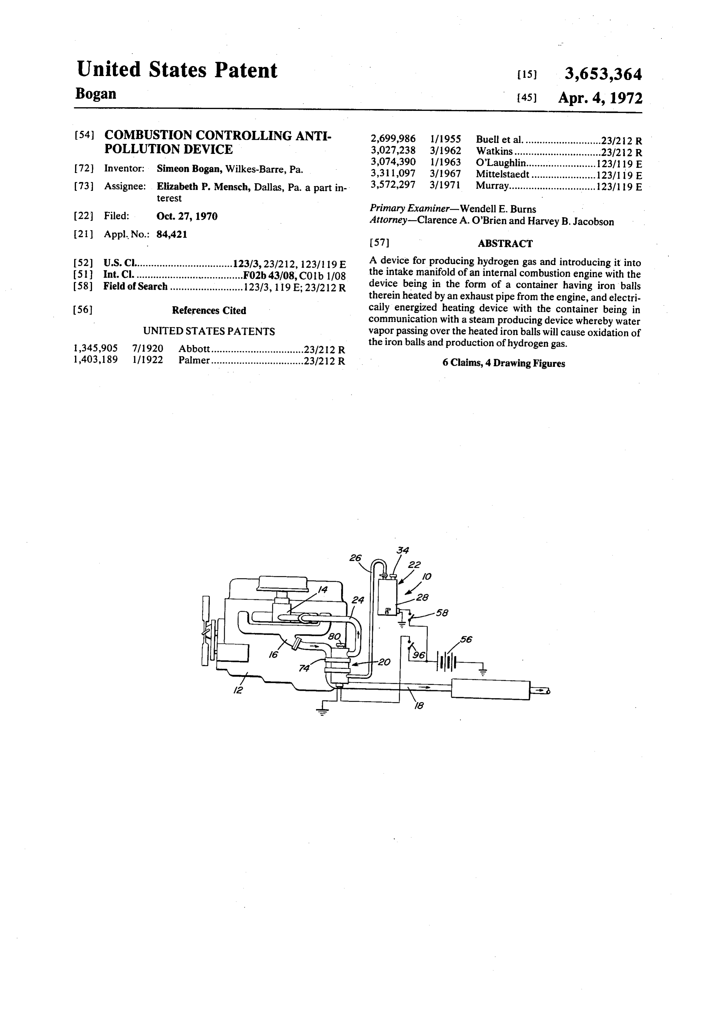
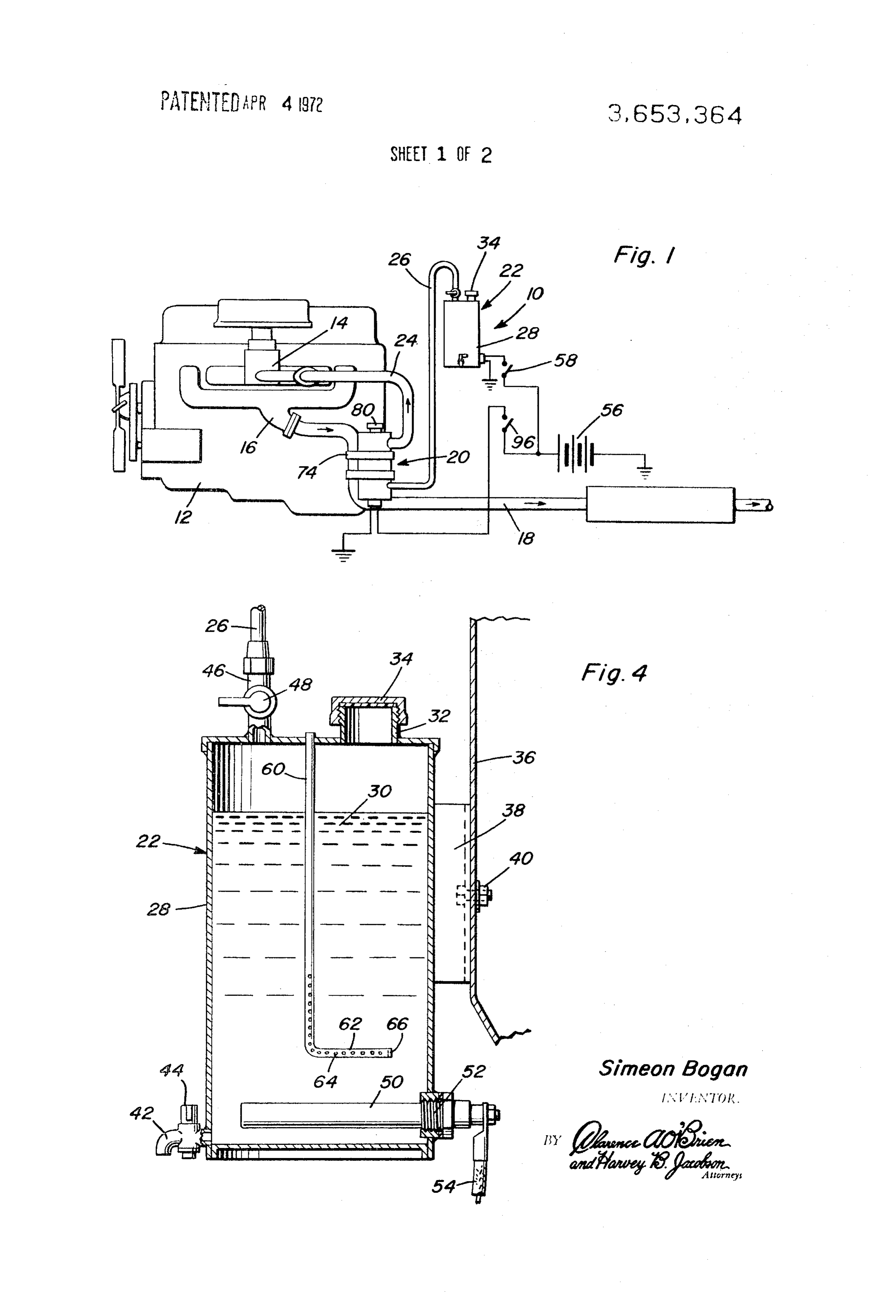
The present invention generally relates to an anti-pollution Referring specifically to FIG. 1, the anti-pollution device of device associated with an internal combustion engine which the 10 present invention is generally designated by the numeral and is illustrated schematically in association with an inter utilizes the heat from the exhaust pipe of the engine for nal combustion engine 12 having the usual intake manifold or producing a hydrogen gas which is introduced into the intake 10 system manifold of the engine with the device also including an elec exhaust14pipe and an exhaust manifold 16 communicated with an 18 in a well known manner. The anti-pollution tric heating device and a vapor producing device for introduc device 10 includes a hydrogen gas producing unit generally ing water vapor into a container having a quantity of heated designated by the numeral 20 and a steam or water vapor iron balls disposed therein.
producing unit 22. The hydrogen gas producing unit 20 is
BACKGROUND OF THE INVENTION 15 communicated with the intake manifold 14 through a suitable Many previous efforts have been made to enable operation hydrogenpipe or conduit 24 communicating with the upper end of the gas producing unit 20. The steam producing unit 22 of an internal combustion engine with reduced emission of un is communicated with the hydrogen producing unit 20 burned hydrocarbons and other air contaminants. One effort through a pipe or conduit 26 which communicates the top of to reduce emission of pollutants from internal combustion en 20 the steam producing unit 22 with the bottom portion of the gines has been directed toward the production of a gas which hydrogen producing unit 20.
is more readily burnable than the usual combustible mixture and the introduction of this gas into the engine. U.S. Pat. No. water vapor to
Referring FIG. 4, the specific details of the steam or producing unit 22 are illustrated and includes a 1,490,975 discloses one type of device for producing free vertically disposed hydrogen for introduction into the engine. This patent em 25 30. The upper end oftank 28 for receiving a quantity of water ploys an acid-saturated vapor passing in contact with zinc or 32 provided with a screwtank the 28 is provided with a filler neck threaded closure cap 34 provided other metal which will chemically combine with the acid to with produce hydrogen. U.S. Pat. No. 1,966,345 also discloses a from aa suitable suitable gasket or the like. The tank 28 is supported support such as the fire wall 36 of an automo device for generating hydrogen in which water vapor is con tive vehicle or the like by the use of a suitable bracket 38 and veyed past iron filings so that the oxygen from the steam will 30 fastening bolts 40 or the like. The bottom of the tank 28 is pro combine with the iron to form iron oxide thus liberating vided with a drain pipe 42 having a manual valve assembly 44 hydrogen from the steam which is introduced into the intake therein for draining water from the tank 30 to enable any sedi manifold. Such previously known devices introduce many ment collected in the bottom of the tank 28 to be drained problems which are extremely difficult to solve. For example, therefrom. The top of the tank 28 is also provided with a acid vapors are quite corrosive and in the event of the supply 35 discharge fitting 46 to which the pipe, conduit or hose 26 is at of zinc becoming exhausted, the acid vapors would be quite tached harmful to the engine components. Also, where only exhaust valve 48with the fitting 46 also having a manually operated therein for selectively communicating the upper end heat is utilized the production of hydrogen gas is inadequate of the container 28 with the hydrogen gas producing unit 20. under some operating conditions, especially during the initial Disposed in the bottom of the tank 28 is a heating unit 50 period of operation of an engine when the discharge of pollu 40 which is replaceable with a screw threaded mounting assembly tants is at the maximum.
52. The heating unit 50 is connected to a conductor 54 electri
SUMMARY OF THE INVENTION cally connected with the vehicle storage battery 56 through a suitable switch 58 so that when the switch is closed and the
It is an object of the present invention to provide an anti 45 battery 56 is charged, the electrical heating unit 50 will heat pollution device in the form of a container having a plurality of iron balls therein and an electric heating device and also the top water 30 thus producing steam or water vapor. Also, the of the tank 18 has a small air tube 60 associated therewith heat exchange relation to the exhaust pipe so that the iron which filings and consequently the steam vapor introduced into the open tohas the upper end thereof disposed above the tank and the atmosphere. The lower end of the tube 60 extends container may be heated by the electric heater and the heat to a point adjacent the bottom of the tank and terminates in a from the exhaust pipe thus assuring a supply of hydrogen gas 50 laterally to the intake manifold even though the heat produced by the openings extending lower end 62 having a plurality of small 64 therein which extend along the horizontal portion exhaust pipe is inadequate for this purpose. 62 and upwardly along a substantial portion of the vertical A further object of the invention is to provide an anti-pollu portion of the tube 60. The air tube 60 enables air to be in tion device which is accurately controlled and provided with 55 troduced safeguards to assure that the engine will operate properly with vapor intointo the tank 28 so that the engine 12 can draw water the device being constructed in such a manner that the engine produced in the hydrogen the producing unit 20 by the vacuum intake manifold. Thus, air will be pulled down will continue to operate in the event the anti-pollution device through becomes inoperative and to maintain safe conditions at all tures 64 the times.
tube 60 and out through the small orifices or aper with the air thus passing up through the water 30 and entraining moisture or water vapor therein as the air passes
Still another important object of the invention is to provide 60 through an anti-pollution device which is simple to install and operate, 20. the conduit 26 into the hydrogen gas producing unit safe, effective for producing hydrogen gas and relatively inex movement of airend
The lower of the tube 60 is closed as at 66 to assure downthrough the tube 60 during operation of pensive to manufacturer and maintain. the engine which will eliminate the production of a vacuum BRIEF DESCRIPTION OF THE DRAWINGS 65 within the tank 28 and also serve as a relief for the tank 28 in the event the heater 50 is left on when there is no demand for
FIG. 1 is a schematic view of the anti-pollution device of the the steam or water vapor.
present
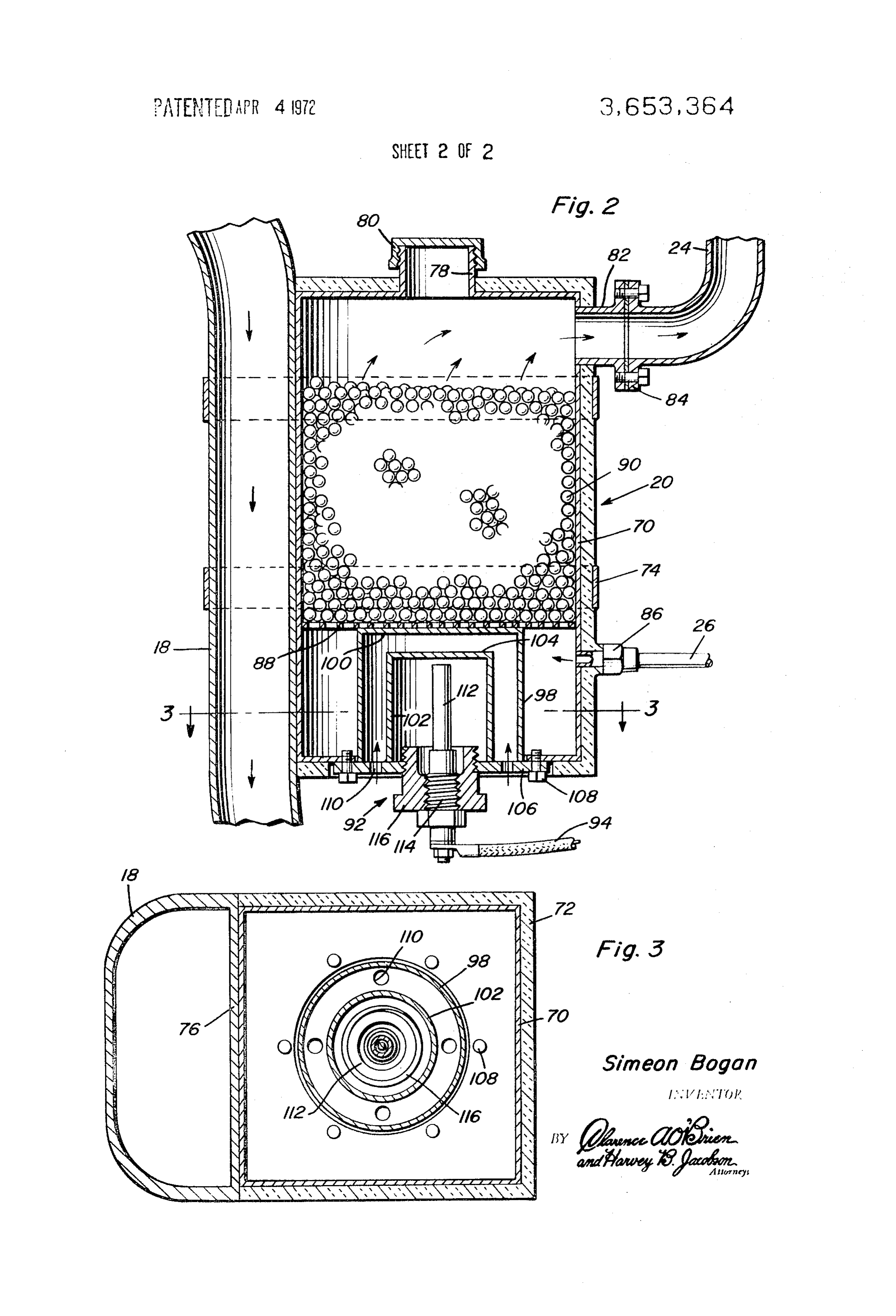
invention associated with an internal combustion en FIGS. 2 and 3 illustrate the details of the hydrogen gas producing unit 20 which includes the vertically disposed tank 9. FIG. 2 is a vertical sectional view of the hydrogen producing 70 70 provided with an exterior insulating layer 72 around three device illustrating the heat exchange mounting on the exhaust sides thereof. The tank 70 is mounted in heat exchange rela pipe and the structural details thereof. tion to the exhaust pipe 18 by clamp bands 74. As illustrated FIG. 3 is a transverse, plan sectional view taken substan in tially upon a plane passing along section line 3-3 of FIG. 2 il withFIG.
the 3, the exhaust pipe has a flat side 76 in engagement flat side wall of the tank 70 to produce a good heat lustrating the structural details of the heating device. 75 exchange relation between the tank 70 and the exhaust pipe
Page 5
18. The top of the tank 70 is provided with a filler neck 78 having a removable screw threaded closure cap 80 forming a provide is mixed with the fuel and air mixture. The hydrogen gas will closure therefor. The upper side wall of the tank 70 is pro higher combustion temperatures and produces more vided with a tubular fitting 82 to which the pipe 24 is con complete combustion of the fuel thus reducing the quantity of unburned hydrocarbons which are exhausted into the at nected by a flange coupling 84 or the like. Adjacent the bot mosphere.
tom of the tank 70, an inlet fitting adapter 86 is provided to remove theThe device is safe in use in that if a person should cap 80 to refill the device with iron balls while the which the water vapor conduit or hose 26 is communicated for engine was running or if the engine was not running and the introducing water vapor or steam into the bottom portion of device was turned on during this operation, no harm would oc the tank 70. cur. If the heating unit 92 burns out, the device will automati Disposed above the inlet adapter 86 is a supporting partition 10 cally shut off and there will not be any build up of hydrogen 88 in the form of a wire screen or the like on which is sup gas.
ported a plurality of iron balls 90 which substantially fill that withThe device may run off of exhaust heat only or it may run the electric heater in operation especially in cold area of the tank above the screen 88 so that as steam passes weather. If the device becomes inoperative during use, there upwardly in the tank 70, it will pass over and around the iron will be a noticeable difference in the operation of the engine in balls. Disposed in the compartment below the partition screen 15 which event the valve 48 may be simply turned off until opera 88 is a heating assembly 92 which is connected through a con tion of the device has been corrected. ductor 94 and a switch 96 to the battery 56 for selectively The foregoing is considered as illustrative only of the princi energizing the electric heating unit. ples of the invention. Further, since numerous modifications The electric heating unit 92 includes an outside tubular unit 20 and changes will readily occur to those skilled in the art, it is 98 including a top wall 100 adjacent the partition screen 88 not desired to limit the invention to the exact construction and and an inside wall 102 also including a top wall 104 with the operation shown and described, and accordingly all suitable inside tube or wall 102 being spaced concentrically from the modifications and equivalents may be resorted to, falling outside tube or wall '98. Both of the tubes or walls 98 and 102 within the scope of the invention. are attached to and supported from a bottom plate 106 that is 25 What is claimed as new is as follows:
removably attached to the bottom wall of the tank 70 by 1. In combination with an internal combustion engine in fasteners 108 thus enabling the heating unit to be removed cluding an intake system and an exhaust system, an anti-pollu and replaced. The plate 106 is provided with a plurality of air tion device comprising a water vapor producing unit, and a holes 110 communicating with the space between the inner hydrogen producing unit having an intake communicated with and outer tubes 102 and 98 which serve as a safety device. 30 the water producing unit and a discharge communicated with Disposed within the inner tube 102 is the heating unit 112 the intake system of the engine, said hydrogen producing unit which has a threaded base portion 114 threaded into an the including a plurality of iron balls in heat exchange relation to adapter or bushing 116 which is threaded into the plate 106. exhaust system of the engine for heating the balls and The vacuum of the intake manifold causes flow of vapor and producing hydrogen when water vapor passes over the heated gas produced by the hydrogen producing unit 20 to be drawn 35 balls.
2. The structure as defined in claim 1 wherein said hydrogen into the engine. If the outside tube 98 of the heater unit burns producing out, the vacuum produced by the intake of the engine will balls unit includes an electric heater associated with the draw air through holes 110 and will not draw any vapor. The for raising the temperature thereof. tube 98 will be constructed of a material less thick than the 3. The structure as defined in claim 2 wherein the water vapor producing unit includes an electric heater for producing tube 102 so that it will oxidize first and will burn through first 40 Steal.
when constructed of iron thus eliminating contact of vapor 4. The structure as defined in claim 3 wherein said electric with the inside tube 102.
heater
In operation, the pipe or conduit 24 is attached to the intake cally spacedin the hydrogen producing device including concentri manifold below the carburetor where air and fuel are mixed so tubular enclosures with the space between the en that when the hydrogen enters at that point, it is mixed with 45 closures being vented to the atmosphere to admit air into the hydrogen generating unit when the outer enclosure becomes the fuel and air into substantially a homogeneous mixture so ruptured.
that each cylinder of the engine will receive the same mixture. 5. The structure as defined in claim 4 wherein the outer en When the engine is warmed up to normal temperature, the closure valve 48 may be actuated. This valve may be actuated from a tion thanis the constructed of oxidizable iron of thinner construc inner enclosure to assure that the outer enclo suitable mechanism extending to a point on the dashboard of 50 sure will rupture prior to the inner enclosure. the vehicle. Water vapor goes into the hydrogen generating 6. The structure as defined in claim 5 wherein said hydrogen unit 20 where it comes into contact with the hot iron balls 90 which releases hydrogen gas in a well known manner with the for enablingunit producing includes a tank having a closure cap thereon the iron balls to be replaced.
hydrogen gas being conveyed to the intake manifold where it sk sk ck ck ck
Provenance
- Collection
- Cited prior art
- Original PDF
- patentimages.storage.googleapis.com →
- Filed
- 1970-10-27
- Pages
- 5
- Method
- pdftotext (the PDF's own text layer) + pdftoppm 300dpi page scans
- Source
- Google Patents bibliographic record
- Granted
- 1972-04-04
- Inventors
- Simeon Bogan
- Transcribed from
- patentimages.storage.googleapis.com →