patent · US3362883
Disposal system for contaminated hydrogen from a nuclear reactor
9 January 1968
Page 1
Drawing sheet — no readable text.
Page 2
United States Patent Office 3,362,883 Patented Jan. 9, 1968
charge, thereby burning it in an inherently safe manner 3,362,883 which is at the same time simply and easily accomplished. DSPOSAL SYSTEM ER O6STAMANATE) It is another object of this invention to provide a con HYDROGEN FROM A NUCLEAR REACTOR taminated hydrogen disposal system which reduces large William E. Wright, Mount Lebanon, Pittsburgh, Pa., as volumes of contaminated hydrogen to water, plus signor to Westinghouse Electric Corporation, Pitts burgh, Pa., a corporation of Pennsylvania chemically inert radioactive gases, and small quantities of Filed Feb. 8, 1966, Ser. No. 525,909 excess oxygen. The relatively small resultant volumes of 3 Claims. (C. 76-37) liquid and non-combustible gases can be processed rou tinely in the radioactive waste disposal systems that are 0 a part of all nuclear power plants.
ABSTRACT OF THE DISCLOSURE Finally, it is an object of this invention to satisfy the An apparatus for disposing of contaminated hydrogen foregoing objects and desiderata in a simple and expe gas containing potentially explosive quantities of oxygen dient manner.
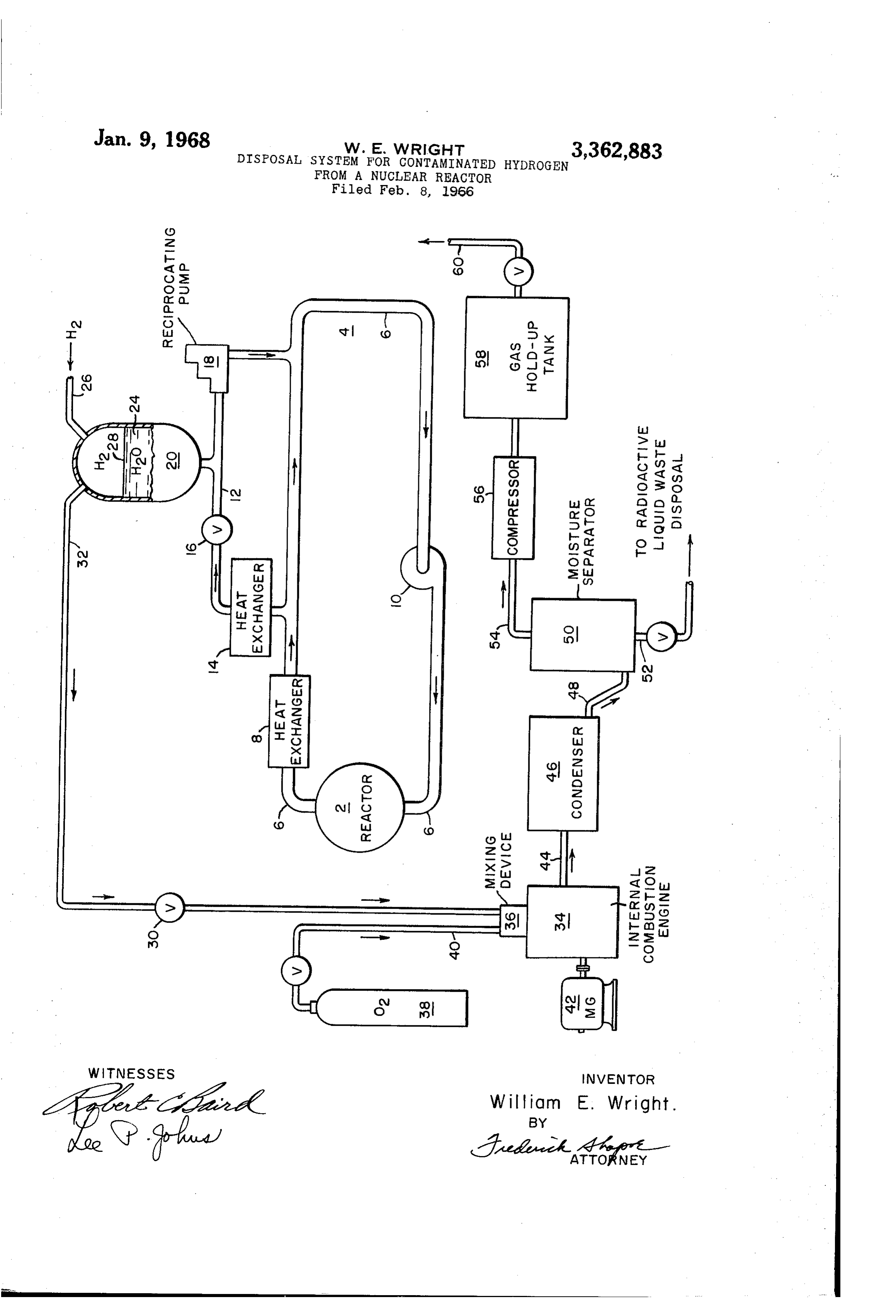
and noxious proportions of radioactive fission gases; the 5 nuclearThe accompanying drawing is a schematic view of a apparatus including an internal combustion engine for reactor system having a hydrogen batch burning converting small increments of hydrogen to water. System associated therewith in accordance with the prin ciples of the invention.
The present invention involves a system for eliminat
Pressurized water cooled nuclear reactors include a ing hydrogen gas which has been contaminated with water cooling system for transferring heat energy from 20 radioactive gaseous fission products during the operation of a nuclear reactor. In a water coolant system for a the nuclear fuel to a steam generating heat exchanger. nuclear reactor a conduit is provided for circulating the Among other components, the cooling System includes a coolant from the reactor and through a heat exchanger surge tank in which the changes in system water volume and back to the reactor. The system also includes a surge are accommodated.
tank in which excess water is stored for maintaining a
The surge tank is a closed vessel normally containing 25 relatively water in the lower portion and hydrogen in the upper constant water volume in the system. The water portion. Within the surge tank occupies the lower portion thereof Hydrogen, rather than some other gas, is used because and the upper portion is occupied by hydrogen gas which hydrogen combines with oxygen dissolved in the water 30 from combines with any oxygen in the water to prevent oxygen and thus minimizes the oxygen content of the water. corroding metal parts of the reactor coolant system. Free oxygen in the water is undesirable because of its During operation of the system the hydrogen may corrosive effect on metal parts constituting the reactor as gradually become contaminated with radioactive fission well as the water cooling system. products and thus becomes an undesirable source of radia Associated with the foregoing is the fact that radio tion. As a result, it is desirable to eliminate the source active fission gases such as krypton and xenon become 35 with by periodically burning off the hydrogen and replacing it dissolved in the water if a leak develops in any of the internal a new uncontaminated supply. For that purpose an fuel tubes within the reactor. Such dissolved gases are combustion engine is provided where the con carried by the water to the surge tank where they escape taminated hydrogen is united with oxygen to form water. into the hydrogen gas atmosphere above the water. If the 40 Other oxidizers such as air or hydrogen peroxide may be used. Subsequently, the water is separated from the concentration of such gases is allowed to become too non-combustible radioactive gases and the contaminated great, the Surge tank gas volume becomes undesirably Water and non-combustible gases are separately disposed radioactive.
Thus, it is desirable to periodically purge and surge of, such as in sealed containers buried in the ground. tank of the contaminated hydrogen gas blanket. Also, 45 Water in the drawing a nuclear reactor 2 is provided with a Whenever the cooling system is opened for maintenance coolant System 4, which system includes a conduit or plant refueling, the hydrogen blanket must be removed. 6, a heat exchanger 8, and a centrifugal pump 10. An In both of these cases an unusual waste product-hydro associated System for accommodating changes in the water gen contaminated with radioactive gases-requires dis volume, such as when the reactor heats up from a cold posal. condition, is provided and includes a conduit 12, a heat Various means of oxidizing the hydrogen to eliminate exchanger i4, a letdown valve 16, a reciprocating pump the combustibility danger of the mixture have been em 18, and a Surge tank 20. The heat exchanger 8 may be of ployed, such as using a platinum catalytic grid or a flame Conventional construction. The pump 10 operates pri recombiner. Another method involves the dilution of the marily to maintain a constant flow of water around the hydrogen with large quantities of an inert gas such as ni 55 The circuit closed of the conduit 6 and through the reactor 2.
Surge tank 20 has the primary purpose of com trogen. However, such methods have serious disadvan pensating for increases and decreases in the water volume tages. The method of diluting with nitrogen requires the storage of large volumes of gas for long periods of time. of the System such as when the water circuit is heated up Both types of recombiners have consistently presented or cooled down. The lower portion of the tank 20 is occu pied by coolant Water 24 and the upper portion is occupied operating difficulties that primarily involved intermittent 80 primarily operation. by hydrogen gas, which is introduced through It has been found that the problem may be overcome an inlet conduit 26. An interface 28 of water and hydro by burning the contaminated hydrogen in an internal com gen gas exists within the surge tank. bustion engine in which the hydrogen is mixed with meas During operation of the reactor 10 the water frequently ured amounts of oxygen and used as the engine fuel. Such 65 absorbs contaminants such as fission products and oxygen a procedure is satisfactory because not only is it not sub formed by hydrolysis. In order to prevent corrosion of the ject to the operating difficulties inherent in prior proce metal parts in the reactor coolant system, the oxygen must dures, but it is relatively inexpensive and simple to use be eliminated from the water as completely as possible. and it is inherently fail-safe. The hydrogen gas serves that purpose. As the water 24 Accordingly, it is a general object of this invention to 70 circulates in and out of the surge tank, the hydrogen gas provide contaminated hydrogen disposal ssytem by burn is absorbed at the interface 28 and combines chemically ing hydrogen in Small batches, i.e., a combustion chamber with any oxygen dissolved in the water.
Page 3
3. tively inexpensive facility which has application in all Over a period of time, however, the hydrogen gas may plants that use a hydrogen blanket over a liquid which become contaminated with various fission products such may contain radioactive gases. as krypton and xenon gases which are highly radioactive Finally, though the device of the present invention is and, therefore, the gas volume becomes an undesirable disclosed as useful in a nuclear reactor system, it is equal radioactivity Source. As a result, the hydrogen gas is peri ly useful in the chemical industry where combustible odically replaced. Also, when the reactor () is shut down gases to be disposed of are contaminated or noxious. for maintenance or fuel replacement purposes, the hydro Various modifications may be made within the spirit gen blanket must be displaced. of the invention.
Disposal of the hydrogen is accomplished by opening a What is claimed is:
valve 30 in a conduit 32 which leads to an internal corn O bustion engine 34 where the hydrogen is mixed in a mix i. In a water coolant system for a nuclear reactor ing device 36 with oxygen gas leading from a source 38 wherein a conduit is provided for circulating water from of oxygen through a conduit 40. The engine 34 is started a reactor and through a heat exchanger and to the reac by an electric motor 42 and when combustion of the oxy tor, and wherein a surge tank communicates with the con gen and hydrogen gases commences, the electric motor is duit for storing water containing contaminants in the turned off and the engine is self-sustaining so long as there lower tank portion and for containing hydrogen gas in is sufficient hydrogen to maintain combustion. the upper tank portion, the combination with said tank of The engine 34 operates on an oxygen rich mixture so a gas fueled internal combustion engine means for burning that the combustion process is as follows: the hydrogen gas with oxygen, said engine means includ ing a hydrogen-oxygen mixing device, conduit means be
H-I-O--gaseous fission products-> tween the upper tank portion and the engine means for HO--O--gaseous fission products--heat conveying hydrogen gas to the mixing device, and a slip plemented source of oxygen attached to the mixing device
The process is started by turning on the motor 42 and to supply oxygen in an amount in excess to react with drawing the hydrogen and oxygen mixture into the coin 2 5 the hydrogen to form water by combustion in the engine bustion chambers of the engine 34. When combustion eaS.
stops for any reason, such as a malfunction or completion 2. The device of claim in which the engine means of the burning of the available hydrogen, the process stops includes means for separating water resulting from the automatically. combustion of hydrogen and oxygen from non-combus The combustion products include water in the form of 30 tible contaminants in the contaminated hydrogen gas. Steam and the non-combustible radioactive gases which 3. The device of claim í in which the engine means in entered the hydrogen gas at the gas-water interface 28 cludes an engine and means for starting the engine. within the tank. 20. The combustion products leave the burner 34 via the outlet 44, and are transmitted to a con References Cited denser 46 where the steam is reduced to water. The water UNITED STATES PATENTS and non-combustible radioactive gases then flow through 2., 183,674 12/1939 Erren ———————————— 123- 27 X an outlet 48 to a moisture separator 50. Inasmuch as the water contains radioactivity, it is removed from the mois 3,028,327 4/1962 Weeks -------------- 176-37 ture separator 50 through an outlet 52 and is disposed of 3,041,134 6/1962 Weeks -------------- 176-37 in a conventional manner for handling radioactive liquid 40 3, 113,913 12/1963 Newton ------------- 176-37 waste products. 3,166,478 1/1965 Lindstrom ----------- 176-37 The non-combustible radioactive gases leave the mois FOREIGN PATENTS ture separator 50 via an outlet 54 and are compressed in 221,254 8/1924 Great Britain.
a gas compressor 56 from where they are transmitted to a gas holding tank 58 to decay to a safe radioactive level 45 OTHER REFERENCES before being disposed of through a conduit 60 leading to J. W. Simpson: Proceedings of International Confer a stack (not shown). ence on the Peaceful Uses of Atomic Energy, vol. 13, Accordingly, the device and process of the present in Power Reactors, pp. 211, 212, 220, 221, 222, and 223. vention is inherently fail-safe. The volume of gas accumu lating and requiring expensive storage facilities is main 50 REUBEN EPSTEIN, Primary Examiner.
tained at a minimum level. The system involves a rela
Provenance
- Collection
- Cited prior art
- Original PDF
- patentimages.storage.googleapis.com →
- Filed
- 1966-02-08
- Pages
- 3
- Method
- pdftotext (the PDF's own text layer) + pdftoppm 300dpi page scans
- Source
- Google Patents bibliographic record
- Granted
- 1968-01-09
- Inventors
- William E Wright; Westinghouse Electric Corp
- Transcribed from
- patentimages.storage.googleapis.com →