patent · US2920710
Vehicle having a solar steam generator
12 January 1960
Page 1
Drawing sheet — no readable text.
Page 2
form 25 has a threaded shaft 30 pivotally secured theres to. The shaft 30 projects through a vertical slot (not shown) in an arm 32 hingedly Secured to the platform 2,920,70 i8 at 34. The platform 26 is clamped to the arm 32 by
WECLE EAWENG A SOLAR SEAM a nut 36 threadedly engaging the shaft 30. This arrange (GENERATOR ment provides for inclination of the solar energy col lector 24 thereby enabling compensation for the earth's
George E. Howard, Bayton, Ohio orbital movement about the sun, as will be described Application December 27, 2956, Seria No. 628,699. subsequently.
O The collector 24 is supported by axles 33 and 39 jour 5 Cairns. (C.189-67) nalled in brackets 40, supporting the axles in spaced parallel relation to the platform 26. A sector gear 32 is Secured to the axie 38. The sector gear 42 engages a pinion 43 driven by an electric motor 46, mounted upon
This invention relates to a solar vehicle and more par 5 a bracket 43 Secured to the platform 26. This arranges ticularly to the combination with a mobile vehicle of a ment provides for rotation of the collector 24 about the Solar energy power Supply adapted to propel the vehicle. axis
The present application is a continuation-in-part of my tion defined by the axles 33 and 39, enabling compensas for the earth's rotation, as will be described subse copending application Serial No. 525,186, filed July 29, quently.
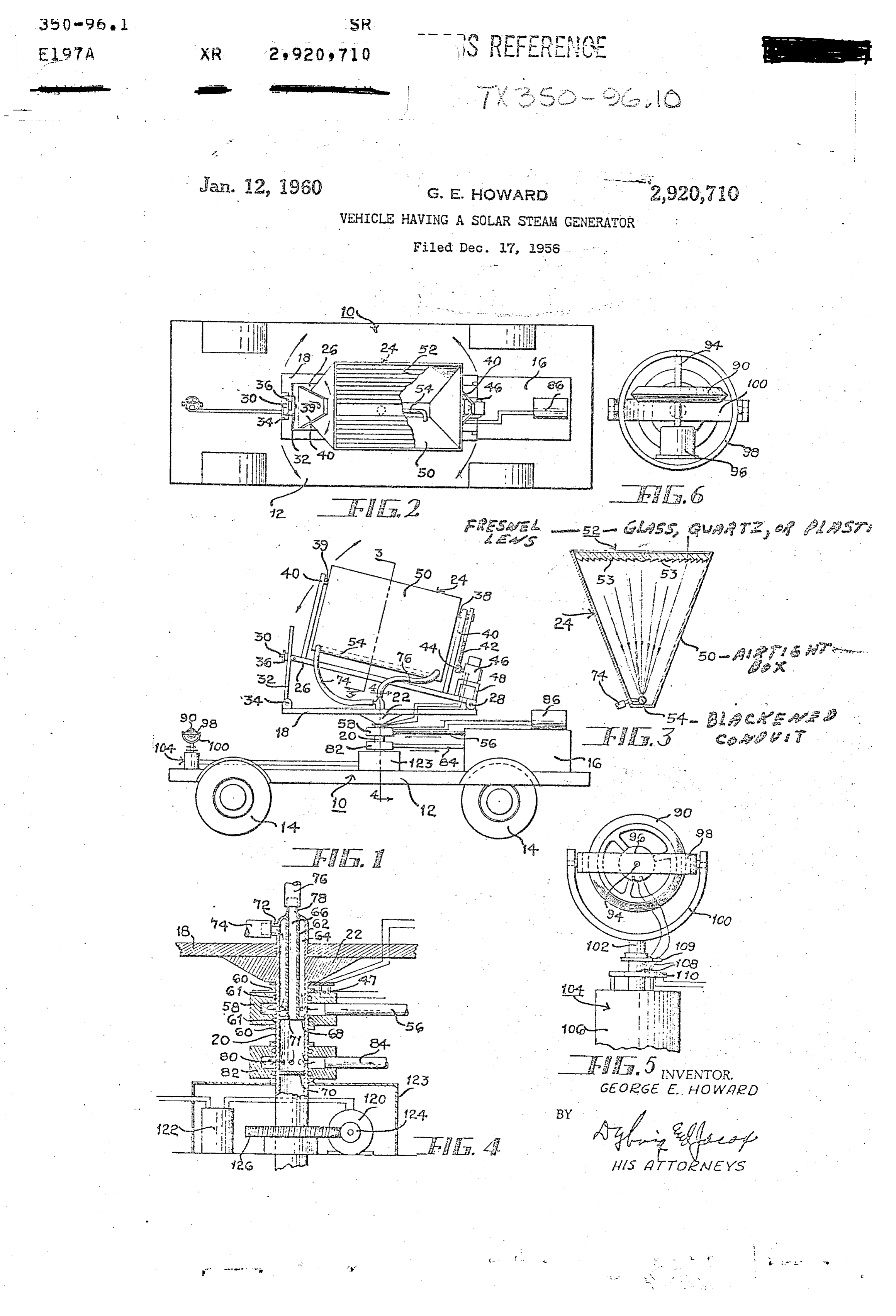
1955, and entitled Solar Energy Converter, which has 20 As illustrated in Figure 3, the collector 24 comprises since become abandoned. a fully enclosed substantially airtight box 50 having a An object of this invention is to provide a solar vehicle trapezoidal cross-section, one side of which is a trans having Solar energy collecting means mounted thereon parent Fresnel plastic, lens 52.orThe arid including means for orienting the collecting means glass, quartz, the Fresnel lens, which like comprises may be a plurality upon the vehicle Such that optimura collection of solar of parallel Éii. sections 53 which are de energy is possible regardless of the direction in which signed, in accordance with well established optical prin the vehicle is moving. ciples, to focus normally incident plane parallel light of Another object of this invention is to provide an effi a predetermined wavelength upon an elongate rectangular cient Solar energy collection and conversion apparatus surface within the box. 50. Light of a greater of lesser adapted to be mounted upon a vehicle for the purpose 30 wavelength will in general pass to one side or the other of of Supplying power for the vehicle. this imaginary rectangle. A metallic conduit 54 is placed Other objects and advantages reside in the construc within the box 50 at substantially the focal plane of the tion of parts, the combination thereof, the method of lens 52. The------------- conduit 54 has a blackened external-sur manufacture and the node of operation, as will become face for optimun light absorption. The arrangement is more apparent from the following description. SC at light of the predetermined focal wavelength as In the drawings, well as light of slightly greater or less wavelength will Figure 1 is a side elevational view of the solar vehicle be focused upon the blackened conduit and absorbed of this invention. thereby. The absorption of light by the conduit 54 pro Figure 2 is a top plan view of the vehicle of Figure 1. duces thermal energy within the conduit, the conduit Figure 3 is an enlarged sectional view taken substan 40 functioning as a boiler, converting solar energy into steam tially along the line 3-3 of Figure 1. energy. By making the box 50 airtight, thermal con Figure 4 is an enlarged fragmentary elevational view, vection currents tending to remove heat from the conduit taken Substantially along the line 4-4 of Figure 1, with 54 and dissipate that heat to the atmosphere are substan parts shown in section, illustrating a mechanism for posi tially eliminated.
tioning the Solar energy collection surface and also illus The steam engine 6 operates on a closed cycle, such trating the construction of fluid conduits utilized in con that the steam utilized in operating the engine is coin veying power from the solar energy converter. densed to water, then recycled through the boiler, that is, Figure 5 is an enlarged elevational view of a gyroscopic the conduit 54. The condensing and recycling apparatus direction indicator employed in this invention. is well established in the art and therefore is not repro Figure 6 is a top plan view of the gyroscopic direction duced herein.
indicator. The condensed water, which is at a temperature near Referring to the drawing in detail, a steam propelled the boiling point, flows from the engine 6 through a con vehicle i0 is illustrated schematically in Figures 1 and 2. duit 56 to a coupler 58 mounted upon the vertical axle The vehicle 10 includes a chassis 12 mounted upon wheels 20. The coupler 58 is rotatably mounted upon the axle 14, the chassis 12 Supporting a closed cycle steam engine 20 between spaced annular bearings 60 secured to the 16. The vehicle 0, may take any desired form, as for axle 20. Leakage around the coupler 5S is obstructed by example, a steam operated automobile, a locomotive, or suitable O-rings 6. The axle 20, which is hollow, as ill a boat, or the like. lustrated in Figure 4, is partitioned by an inner tubular In the present invention, Solar energy is collected on sleeve 62 into two co-axial conduits 64 and 66. An aper the vehicle and utilized to generate steam for operating 60 tured plate 68 at one end of the sleeve 62 terminates the the steam engine. The Solar energy collecting apparatus outer conduit 64 and a plate 70 disposed in spaced rela is illustrated in Figures 1, 2, 3, and 4. This apparatus is tion to the plate 68 terminates the inner conduit 66. The supported by a horizontal platform 18 which, in turn, coupler 58 communicates with the outer conduit 64 in the is rotatably mounted upon a vertical axle 20 journalled axle 20 through perforations 71 in the outer wall of the in the chassis 12. The axle 20 is provided with a conical axle 20. This permits the water to flow upwardly in the flange portion 22 serving as a seat for the platform 18. axle 20 to an outlet 72 disposed above the platform 13. The platform is mounted so as to rotate independently of From the outlet 72, the water flows through a flexible the axle 20, however, friction between the platform 8. hose 74 to one end of the conduit 54. and the conical flange portion 22 restrains such rotation. Within the conduit 5., steam is generated, the steam. The solar energy collector 24 is mounted upon a Sec flowing through a flexible hose 76 to an inlet 73 com ord platform 26, having one end thereof hingedly secured municating with the inter condu: 66 in the axle 20. to the platform 18 at 28. The opposite end of the plat From the inner conduit 56, the steam flows through per
W W h
Page 3
t M (i.
forations 8 in the outer waii of the axle 20 to a sec with precision with the aforesaid gyroscope only if the ond rotary coupler 82 identical to the coupler 58. From gyroscopic axis is parallel to the earth's axis of rotation. the coupler 32, the steam flows through a conduit 34 to If the gyroscopic axis is not parallel to the earth's axis, the engine 6. Although not illustrated, suitable insula the gyroscope will appear to precess as the earth revolves. tion may be provided for the various steaIn and water 5 The apparent precession is more or less pronounced de conduits. It is to be noted that the outer conduit 6i in pending upon the starting position of the gyroscopic axis. the axle 20 forms a warm water jacket for the inner con Where the axis points north and south and is horizontal, duit 66 through which the steam flows. the apparent precession is nill at the equator, where the The apparatus thus far described, namely the combina gyroscopic axis would be substantially parallel to the tion of a solar energy collector, a solar energy converter, O earth's axis, and nost pronounced at the poles, where the and a steam engine is recognized as old in the art, the gyroscopic axis would be normal to the earth's axis. combination being but one of the many systems available Since the solar vehicle operates only during daylight for the utilization of solar energy. If the axis defined hours, the precision of positioning afforded by a nere by the axles 38 and 39 is oriented in a north-south di horizontally disposed gyroscopic axis pointing substan rection and if the platform 26 is inclined such that the tially north and South is sufficient for most purposes in sun rays strike the Surface of the lens 52 normally, the the temperature and tropical regions. The tedious task combination may be operated as a stationary steam en of starting the gyroscope on an axis parallel to the earth's gine. Of course, it is necessary to utilize a portion of axis may therefore be eliminated. the output of the steam engine to drive a generator 36 The indicating synchro motor 103 associated with the for energizing electrically the notor 45 to rotate the col 20 north indicating gyroscope is connected electrically to lector 24 in synchronism with the earth's rotation, there a power synchro notor 26 through a balancing unit 22 by always maintaining the prisinatic lens turned toward housed in a housing 23. The power synchro motor 20 the sun. controls the position of the axle 20 through a worm 24 in the present invention the solar collector 24 is mount engaging a gear 26 Secured to the axle 20. The indicat ed upon a vehicle. For successful operation of the mov 25 ing and power synchro Inotors constitute a conventional ing solar collector 24, it is necessary that the solar col position control servo system, wherein the position of the lector be trained upon the sun regardless of the direction axle 20 relative to the chassis 2 is determined by the in which the vehicle moves. To accomplish this, the plat position of the shaft 102 in the indicating synchromotor form i8, upon which the solar energy collection mecha 30 i04 relative to the housing 106. Thus, the horizontal inism is mounted, is rotated relative to the chassis 12 by projection of the axis defined by the axles 38 and 39 in a servo system which responds to a north-south indicat the collector apparatus may be maintained parallel to the ing device. horizontal projection of the gyroscopic axis, that is, in The indicating device illustrated in detail in Figures 5 a general north-south direction. Minor adjustments in and 6 is mounted upon the chassis 2 at any convenient 3 5 the alignment of these axles may be made by manually place. The indicating device comprises a flywheel 90 rotating the platform 8 relative to the axle 20. mounted upon the shaft 94 of an electric motor 96. The Electrical power for operating the servo system, the motor and shaft are mounted within a ring 98, in such gyroscope motor 96, and the motor 46 is derived from a manner that the shaft 93 is free to rotate. The ring the generator 86 operated by the steam engine. Battery 98, in turn, is mounted within a gimbal 90 so as to 40 power may be employed for operating these motors at rotate about an axis extending normal to and intersect start-up times before steam power is available. Electric ing the axis of rotation of the shaft 9-3. The masses of power is supplied to the motor 46 through slip ring con the fiywheel 90 and motor 96 are balanced about the tacts 47 mounted on the coupler 53. axis of rotation of the ring 98. In general, three conditions must be met before this The gimbal 100 is mounted upon the vertical shaft 102 invention will operate efficiently. First, the axis defined of an indicating synchro motor 104. The housing 36 by the axles 33 and 39 must be positioned substantially of the synchromotor 04 is fixedly secured to the chassis normal to the plane defined by the earth's orbit about i2. The notor 96 is energized through contacts 98 the sun; second the horiozintal projection of this axis must supported by a bracket 69 carried by the shaft 32, the xtend substantially north and south; and third, the plat contacts engaging slip rings 20 secured to the motor form 8 must be horizontal.
housing 306. The vehicle may be employed effectively as a farm The flywheel 96, when rotated at high speed by the tractor where the land is substantially level. Non-lini motor 96, has the property of rotational inertia, in that formities in the contour of the laid will merely produce it resists any force tending to change the direction of its on overal reduction in the operating efficiency of the axis of rotation in space. If the flywheel 90 is initially collector 24 which can be compensated for by enlarging rotated in a vertical plane such that its axis of rotation the collectoriens 52.
is horizontai, the mounting is such that the axis of rota The device is limited in that it can travel for only a tion of the flywheel 90 will remain horizontal regard short distance in any given direction. Obviously, should less of the tilt of the chassis 2 away from the horizon the vehicle travel in an east or west direction for any tal. Any tilt of the chassis 2 is resolved into two mo 60 appreciable distance, the synchronism of the motor 46 tions relative to the axis of rotation of the flywheel 90, with the rotation of the earth would be in material error. one being rotational motion of the gimbal 90 relative Similarly, an appreciable movement of the vehicle north to the ring 98, which remains horizontal, and the other or south would produce a material error in the inclina being a pure translation of the rotational axis in space, tion of the platform 26. For this reason, the vehicle is without change in direction. If the vehicle is turned on essentially a vehicle of restricted movement, wherein its a horizontal plane, the axis of rotation of the flywheel usefulness is confined to a relatively small area such as a 90 will retain its fixed direction in space and the hous farm, a town, or a Small lake. Any distance travel ing 106 of the indicating synchro motor 104 will turn would necessarily require periodic adjustments of the relative to the shaft 102. In effect, then, the flywheel cotector mechanism.
90 is mounted like a gyroscope, in that the axis of rota It is to be understood that this invention, which relates tion of the flywheel 90 may retain its fixed direction in to the useful combination of a Solar energy now cr Sup space regardiess of the novement of the vehicle it. ply with a mobile vehicle is not limited in scope to the The gyroscope described establishes an axis which is creation and utilization of steam power, but rather en fixed in space. For the present purposes, however, it is braces any system by which motive power may be ob necessary to have an axis which is fixed relative to that tained fron Solar energy.
of the earth's rotation. Such an axis can be obtained Although the prefer Ted embodiment of the device has
Page 4
been described, it will be understood that within the tion, motive means for propelling the vehicle, solar purview of this invention various changes may be made energy collecting means, and power conversion means in the form, details, proportion and arrangement of parts, energized by the Solar energy collected for supplying . the combination thereof and mode of operation, which generally stated consist in a device capabie of carrying 5 power means to said motive means, said solar energy collecting including a generally planar light collecting ele out the objects appended claims. set forth, as disclosed and defined in the ment and means for Supporting said element on said Having thus described try invention: E claim:
vehicle in a plane substantially normal to the sun's rays,
. In a self-gropelled vehicle including, in combinae said last named means including axle means defining a tion, motive means for propelling the vehicle, solar 0 arotational means for axis parallel to the plane of said element, rotating said element about said axis at a energy collecting means, and power conversion means energized by the solar energy collected for supplying for inclining said equal rate substantially to the earth's rotation, and neans axis to the horizontal whereby said axis power to Said motive means, said solar energy collecting when extending north and South may be oriented normal . .: means including a light collecting lens and means for to the plane defined by the earth's orbit about the sun, supporting said lens on said vehicle substantially normal the improvement including means providing a north to the sun's rays, said last named reans including axle south axis on said vehicle, and means for maintaining . . . Eileans defining a rotational axis parallei to the plane of the horizontal projection of said rotational axis parallel ... said lens, means for rotating said lens about said axis ag. . . to said north-south axis. . . . . . .. . ... - . a rate substantially aqua to the rates of the earth's rota 5. A device for collecting solar energy on a movable tion, and means for inclining said axis to the horizontal whereby said axis when extending north and south may . . vehicla comprising, in cornbination, a generally planar light collecting element, and means supporting said ele- :
be oriented not inai to the plane defined by the earth's "... ment on said vehicle in a plane substantially normal to . . . orbit about the Sun, the improvement including means the suga's rays; said last named means including axle providing a north-south axis or said vehicle, and means means defining a rotational axis parallel to the plane for maintaining the horizontal projection of said rotar of said collecting element, means for rotating said collect tional axis parallel to said north-south axis. ing element about said axis at a rate substantially equal 2. In a self-propelled vehicle, the improvement accorde to the earth's rotation, means for inclining said axis to ing to claira i whereira the means providing a north-south the horizontai whereby said axis when extending aorth axis on said vehicle includes a gyroscope. and south may be oriented normal to the plane defined 3. In a self-propelled vehicle, the improvernent ac 30 by the earth's orbit around the sun, means providing a cording to clair. winerein the means providing a northa
South axis on said vehicle includes a gyroscope, and the horizontal projection vehicle north-south axis on Said and naeans maintaining wherein the means for maintaining the horizontal pro to said north-south axis. . . . .rotational of said
axis parallel
jection of said rotational axis parallel to said north south axis comprises an indicating synchro notor respon 35 ... References Cited in the file of this patent sive to said gyroscope and a power synchro motor coul UNITED STATES PATENTS pled with said indicating synchro notor for positioning iii,644. Hermanca. ------- Feb. 7, 1871 the rotational axis of said collecting means in predetera 698,232 Straker -------------- Apr. 22, 1902 mined relationship to the rotational axis of said gyro 726,967 . . Mills e8 al. -------------- May 5, 1903 Scope.
4. In a self-propelled vehicle including, in combina 2249,642 Turges -a-...-------- July 15, 1952. . . .
Provenance
- Collection
- Cited prior art
- Original PDF
- patentimages.storage.googleapis.com →
- Filed
- 1956-12-17
- Pages
- 4
- Method
- pdftotext (the PDF's own text layer) + pdftoppm 300dpi page scans
- Source
- Google Patents bibliographic record
- Granted
- 1960-01-12
- Inventors
- George E Howard
- Transcribed from
- patentimages.storage.googleapis.com →