patent · US4459974A
Solar bottle
17 July 1984
Page 1 — bibliographic record
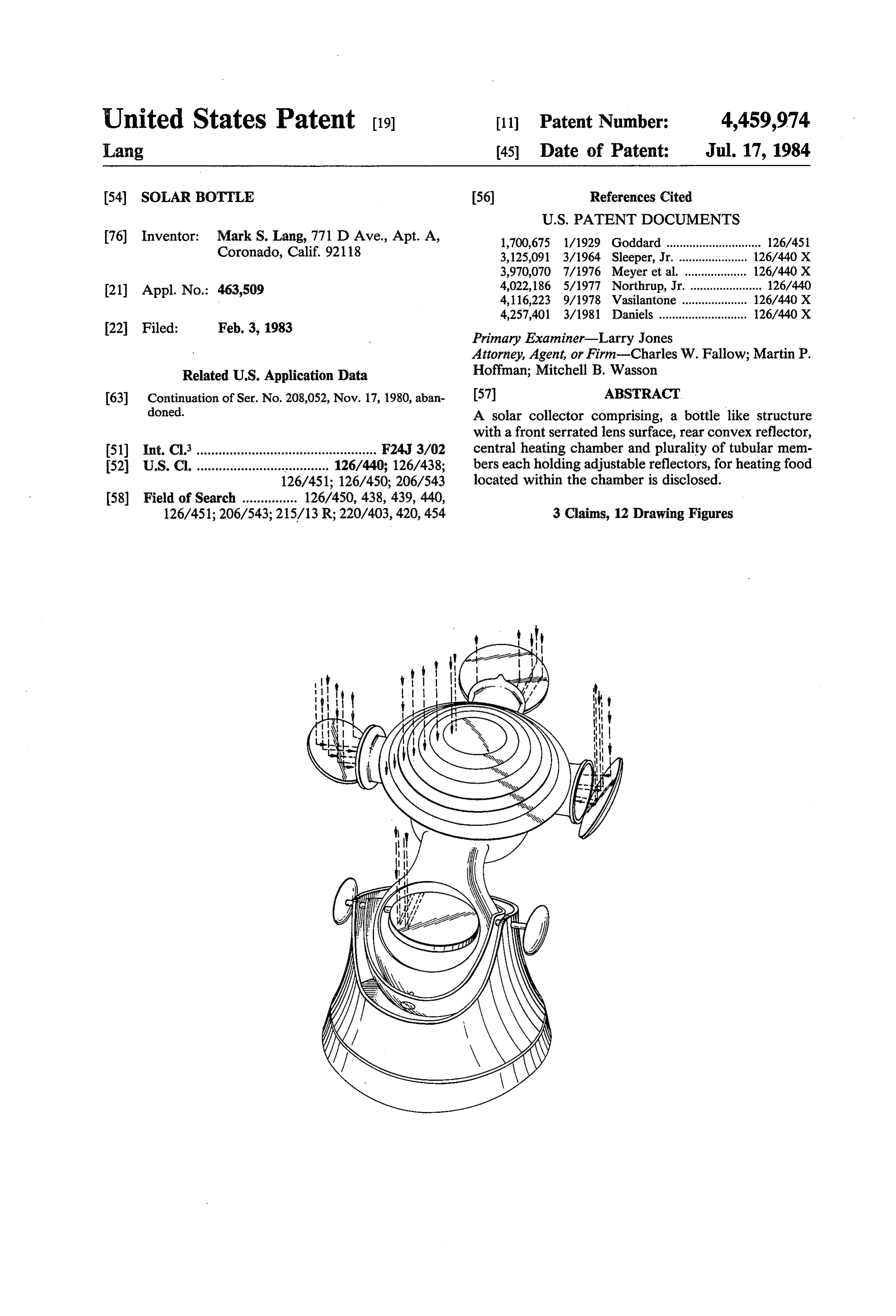
United States Patent (19) 11 Patent Number: 4,459,974 Lang 45 Date of Patent: Jul. 17, 1984 (54) SOLAR BOTTLE 56) References Cited
76) Inventor: Mark S. Lang, 771 D Ave., Apt. A, 1,700,675 l/1929 Goddard ............................. 126/451 Coronado, Calif. 921 18 3,125,091 3/1964 Sleeper, Jr. ..... ... 126/440 X 3,970,070 7/1976 Meyer et al. ... ... 126/440 X 21) Appl. No.: 463,509 4,022,186 5/1977 Northrup, Jr. .. a 126/440
4,257,401 3/1981 Daniels ....... ... 126/440 X 22 Filed: Feb. 3, 1983 Primary Examiner-Larry Jones Attorney, Agent, or Firm-Charles W. Fallow; Martin P.
Related U.S. Application Data Hoffman; Mitchell B. Wasson 63 Continuation of Ser. No. 208,052, Nov. 17, 1980, aban 57 ABSTRACT doned. A solar collector comprising, a bottle like structure with a frontserrated lens surface, rear convex reflector, (51) Int. Cli................................................. F24, 3/02 central heating chamber and plurality of tubular mem 52 U.S. Cl. ........................ses a sess sooe 126/440; 126/438; bers each holding adjustable reflectors, for heating food 126/451; 126/450; 206/543 located within the chamber is disclosed.
126/451; 206/543; 215/13R; 220/403, 420, 454 3 Claims, 12 Drawing Figures
Page 2
Drawing sheet — no readable text.
Page 3
Drawing sheet — no readable text.
Page 4
Drawing sheet — no readable text.
Page 5
Drawing sheet — no readable text.
Page 6
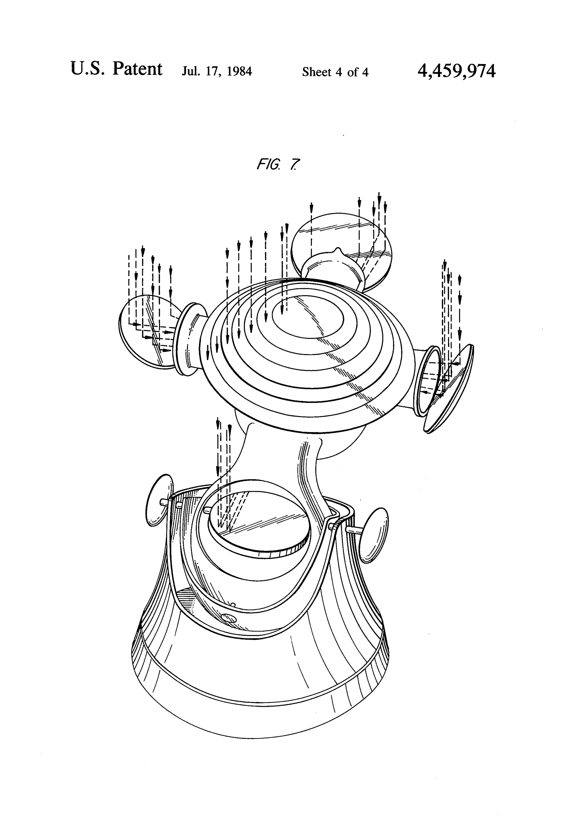
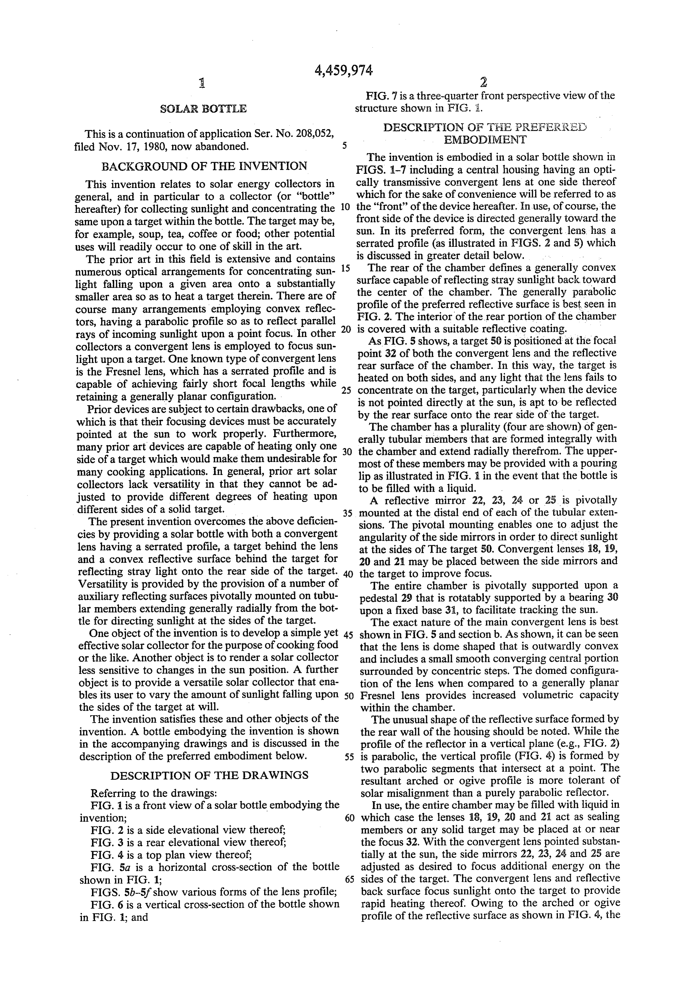
FIG. 7 is a three-quarter front perspective view of the
SOLAR BOTTLE structure shown in FIG. A.
DESCRIPTION OF THE PREFERRED
This is a continuation of application Ser. No. 208,052, EMBODIMENT filed Nov. 17, 1980, now abandoned.
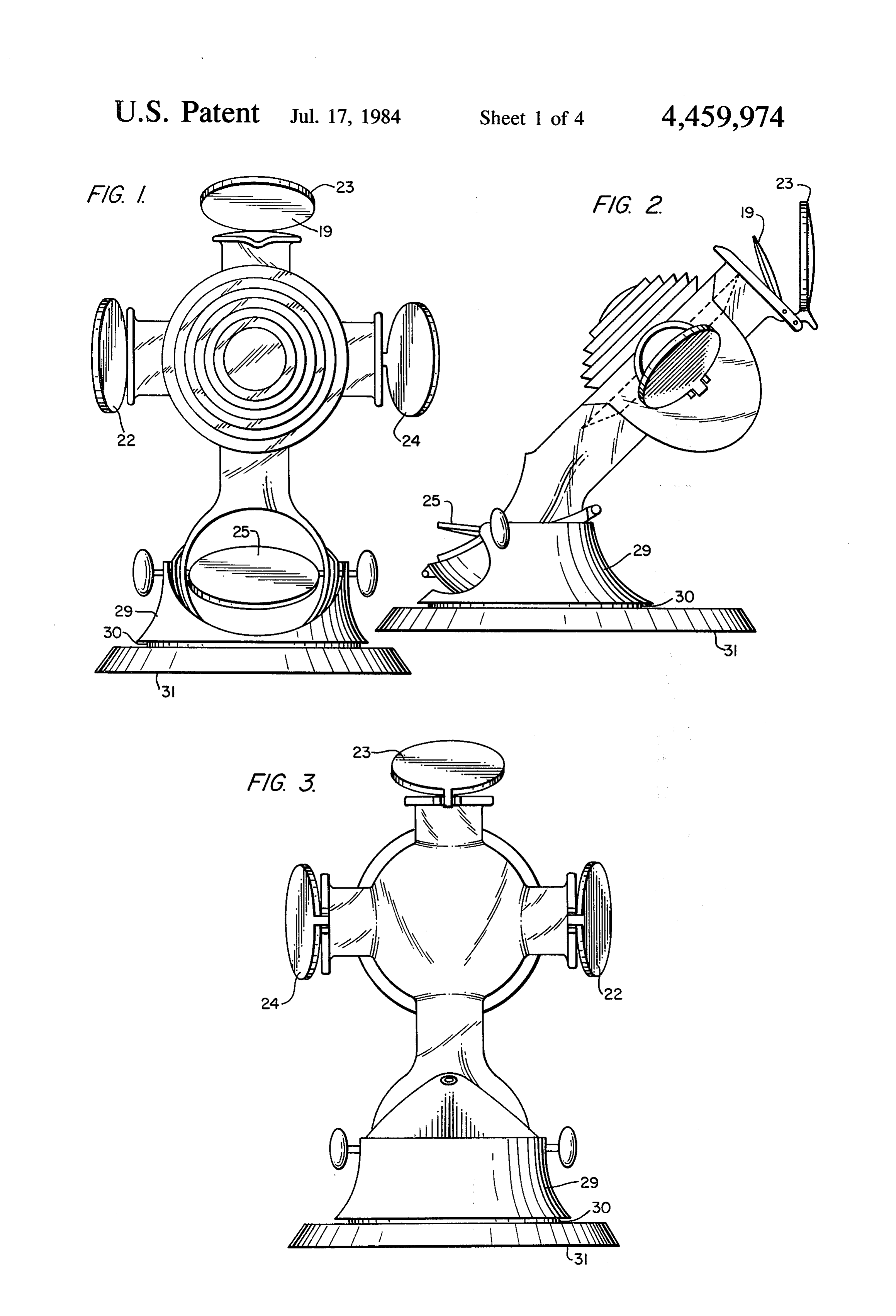
The invention is embodied in a solar bottle shown in
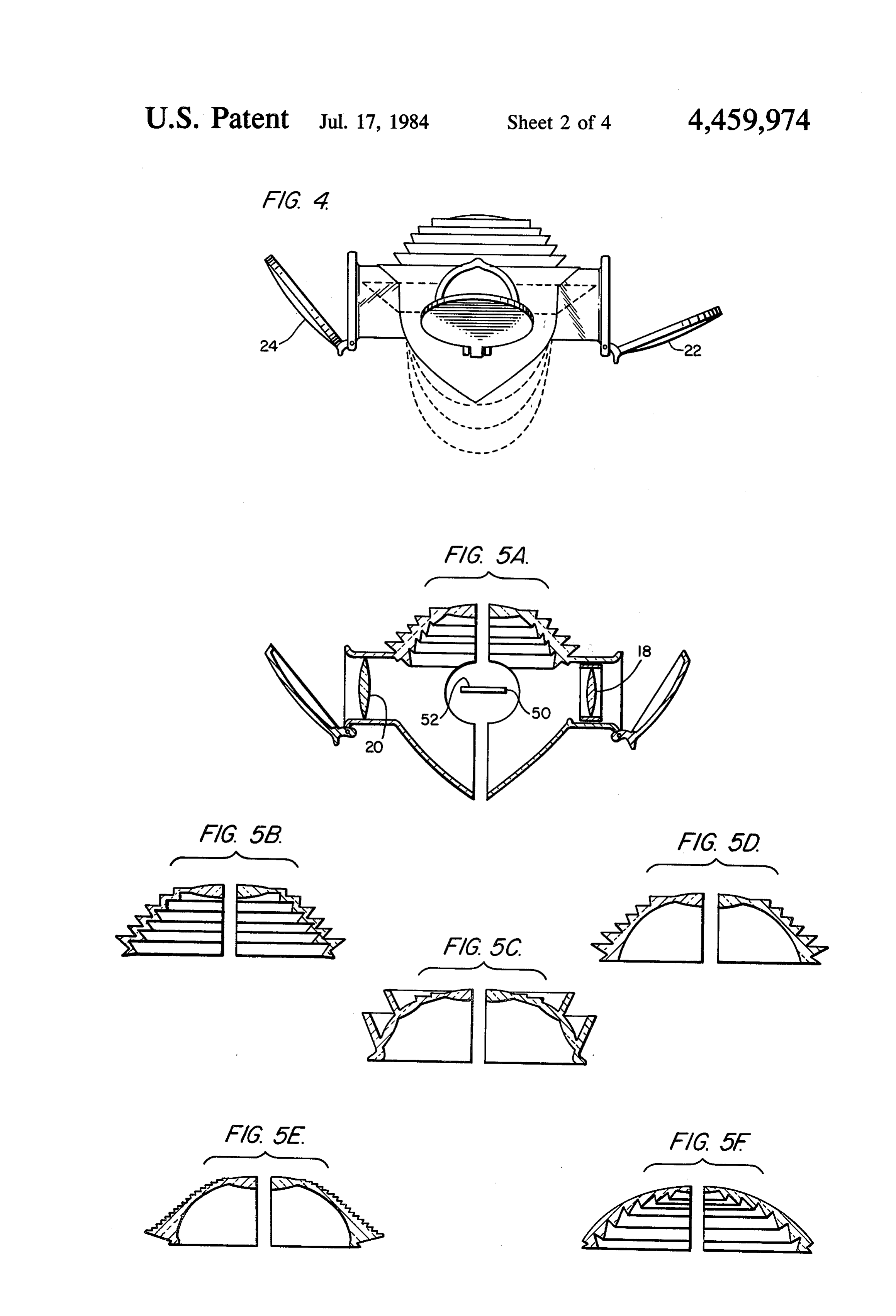
BACKGROUND OF THE INVENTION FIGS. 1-7 including a central housing having an opti This invention relates to solar energy collectors in cally transmissive convergent lens at one side thereof general, and in particular to a collector (or "bottle' which for the sake of convenience will be referred to as hereafter) for collecting sunlight and concentrating the 10 the "front' of the device hereafter. In use, of course, the same upon a target within the bottle. The target may be, front side of the device is directed generally toward the for example, soup, tea, coffee or food; other potential sun. In its preferred form, the convergent lens has a uses will readily occur to one of skill in the art. serrated profile (as illustrated in FIGS. 2 and 5) which The prior art in this field is extensive and contains 15 is discussed in greater detail below. - numerous optical arrangements for concentrating sun The rear of the chamber defines a generally convex light falling upon a given area onto a substantially surface capable of reflecting stray sunlight back toward smaller area so as to heat a target therein. There are of the center of the chamber. The generally parabolic course many arrangements employing convex reflec profile of the preferred reflective surface is best seen in tors, having a parabolic profile so as to reflect parallel 20 FIG. 2. The interior of the rear portion of the chamber rays of incoming sunlight upon a point focus. In other is covered with a suitable reflective coating. As FIG. 5 shows, a target 50 is positioned at the focal collectors a convergent lens is employed to focus sun point 32 of both the convergent lens and the reflective light upon a target. One known type of convergent lens rear surface of the chamber. In this way, the target is is the Fresnel lens, which has a serrated profile and is heated on both sides, and any light that the lens fails to capable of achieving fairly short focal lengths while 25 concentrate on the target, particularly when the device retaining a generally planar configuration.
Prior devices are subject to certain drawbacks, one of by the rear surface ontoatthe is not pointed directly the sun, is apt to be reflected rear side of the target.
which is that their focusing devices must be accurately pointed at the sun to work properly. Furthermore, erally tubular members that are(four
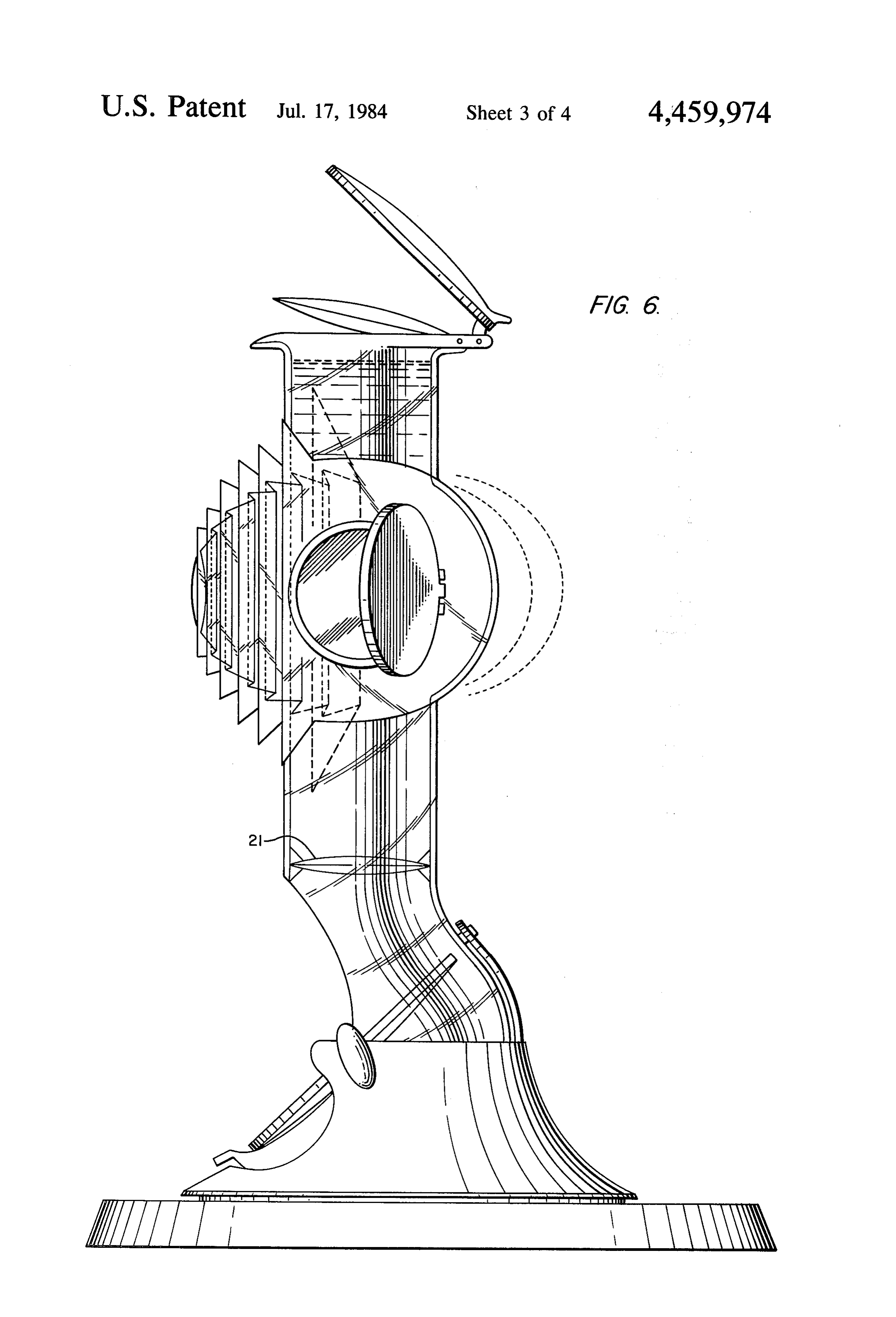
The chamber has a plurality are shown) of gen formed integrally with many prior art devices are capable of heating only one 30 the chamber and extend radially therefrom. side of a target which would make them undesirable for most of these members may be provided withThe a upper pouring many cooking applications. In general, prior art solar lip as illustrated in FIG. 1 in the event that the bottle is collectors lack versatility in that they cannot be ad justed to provide different degrees of heating upon to Abe reflective filled with a liquid. mirror 22, 23, 24 or 25 is pivotally different sides of a solid target. 35 mounted at the distal end of each of the tubular exten The present invention overcomes the above deficien sions. The pivotal mounting enables one to adjust the cies by providing a solar bottle with both a convergent angularity of the side mirrors in order to direct sunlight lens having a serrated profile, a target behind the lens at the sides of The target 50. Convergent lenses 18, 19, and a convex reflective surface behind the target for 20 and 21 may be placed between the side mirrors and reflecting stray light onto the rear side of the target. 40 the target to improve focus.
Versatility is provided by the provision of a number of The entire chamber is pivotally supported upon a auxiliary reflecting surfaces pivotally mounted on tubu pedestal 29 that is rotatably supported by a bearing 30 lar members extending generally radially from the bot upon a fixed base 31, to facilitate tracking the sun. tle for directing sunlight at the sides of the target. The exact nature of the main convergent lens is best One object of the invention is to develop a simple yet 45 shown in FIG. 5 and section b. As shown, it can be seen effective solar collector for the purpose of cooking food that the lens is dome shaped that is outwardly convex or the like. Another object is to render a solar collector and includes a small smooth converging central portion less sensitive to changes in the sun position. A further surrounded by concentric steps. The domed configura object is to provide a versatile solar collector that ena tion of the lens when compared to a generally planar bles its user to vary the amount of sunlight falling upon 50 Fresnel lens provides increased volumetric capacity the sides of the target at will. within the chamber.
The invention satisfies these and other objects of the The unusual shape of the reflective surface formed by invention. A bottle embodying the invention is shown the rear wall of the housing should be noted. While the in the accompanying drawings and is discussed in the profile of the reflector in a vertical plane (e.g., FIG. 2) description of the preferred embodiment below. 55 is parabolic, the vertical profile (FIG. 4) is formed by DESCRIPTION OF THE EDRAWINGS two parabolic segments that intersect at a point. The resultant arched or ogive profile is more tolerant of
Referring to the drawings: solar misalignment than a purely parabolic reflector. FIG. 1 is a front view of a solar bottle embodying the In use, the entire chamber may be filled with liquid in invention; 60 which case the lenses 18, 19, 20 and 21 act as sealing FIG. 2 is a side elevational view thereof; members or any solid target may be placed at or near FIG. 3 is a rear elevational view thereof; the focus 32. With the convergent lens pointed substan FIG. 4 is a top plan view thereof; tially at the sun, the side mirrors 22, 23, 24 and 25 are FIG. 5a is a horizontal cross-section of the bottle adjusted as desired to focus additional energy on the shown in FIG. 1; 65 sides of the target. The convergent lens and reflective FIGS. 5b-5f show various forms of the lens profile; back surface focus sunlight onto the target to provide FIG. 6 is a vertical cross-section of the bottle shown rapid heating thereof. Owing to the arched or ogive in FIG. 1; and profile of the reflective surface as shown in FIG. 4, the
Page 7
device continues to focus sunlight upon the target even a convex reflector defining the rear boundary of said as the sun moves from its original position directly in heating chamber, front of the convergent lens. said convergent lens and said reflective surface being Virtually the entire unit may be made out of inexpen arranged so as to focus incident light upon a com sive molded plastic material so that it can be manufac mon target within the chamber, tured in quantity at very little expense. The construc a plurality of tubular members extending radially tion is simple, yet surprisingly effective and is capable of from said chamber, and many equally useful applications. a like plurality of side mirrors, The structure shown in the drawings and described O one of said mirrors being mounted at the end of each of said tubular members for reflecting additional above is but one embodiment of the subject invention light into said chamber, and should not be taken as in any way limiting the scope said side mirrors being pivotally mounted upon their of the following claims. respective tubular members so that the amount of What is claimed is: light reflected into said chamber by each of said 1. A solar collector comprising 15 side mirrors can be regulated. a convergent lens having a concentrically serrated 3. A solar collector comprising surface and forming the front boundary of a heat a housing defining a treating chamber, ing chamber, a convergent lens forming the front boundary of the a convex reflector defining the rear boundary of said chamber, heating chamber, 20 said lens having a first surface nearer said heating said convergent lens and said reflective surface being chamber and a second surface further from said arranged so as to focus incident light upon a com heating chamber, mon target within the chamber, both of said surfaces having concentric serrations, a housing formed integrally with said reflector, a convex reflector defining the rear boundary of said a plurality of tubular members extending radially 25 heating chamber, from said housing, and said lens and said reflector being arranged so as to focus incident light upon a common target within a plurality of side mirrors, each of said mirrors being the chamber, pivotally mounted upon the distal end of a respec a plurality of tubular members extending radially tive one of said tubular members whereby each 30 from said housing, and mirror can be adjusted to regulate the amount of a plurality of side mirrors, each of which is pivotally light reflected through its respective tubular mem mounted upon the distal end of a respective one of ber into said heating chamber. said tubular members whereby each mirror can be 2. A solar collector comprising adjusted to regulate the amount of light reflected a convergent lens having a concentrically serrated 35 through its respective tubular member into said surface and forming the front boundary of a heat heating chamber.sk k s 3k k ing chamber,
Provenance
- Collection
- Patents citing this work
- Pages
- 7
- Method
- pdftotext (the PDF's own text layer) + pdftoppm 300dpi page scans
- Patent office record
- patents.google.com →
- Source
- Google Patents citing-documents table
- Assignee
- Lang Mark S
- Inventors
- Mark S. Lang
- Published
- 1984-07-17
- Transcribed from
- patentimages.storage.googleapis.com →