patent · US3125091
Inflatable solar energy collector
17 March 1964
Page 1
SR CROSS REFERENCE SEARCH ROOM
March 17, 1964 H. P. SLEEPER, JR 3,125,091
INFLATABLE SOLAR ENERGY COLLECTOR
Filed Sept. 17, 1962 4. Sheets-Sheet
HARVEY P. SLEEPER, JR.
denoc 8. 36 occ
s . . s. 1 -
Page 2
Drawing sheet — no readable text.
Page 3
Drawing sheet — no readable text.
Page 4
Drawing sheet — no readable text.
Page 5
United States Patent Office 3,125,091 Patented Mar. 17, 1964
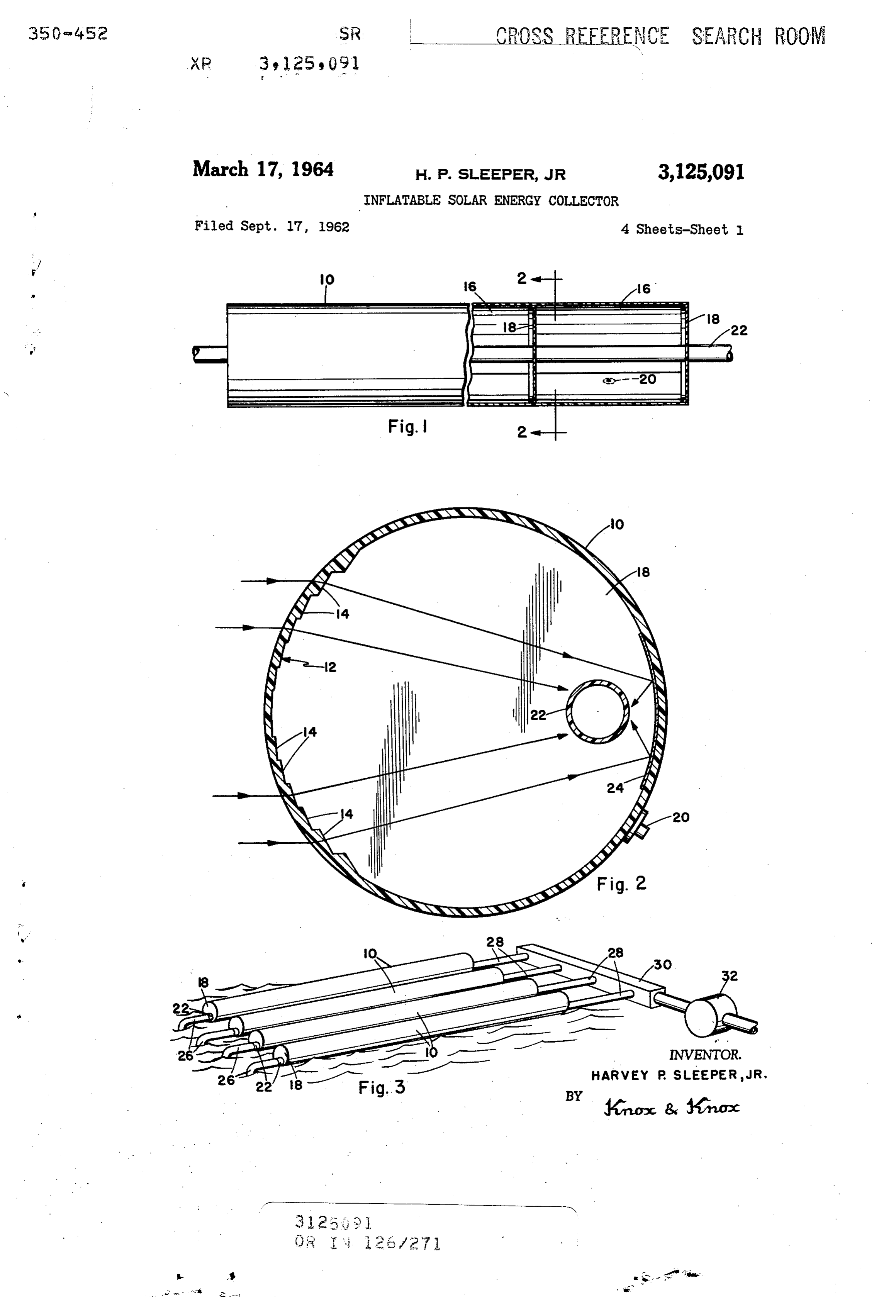
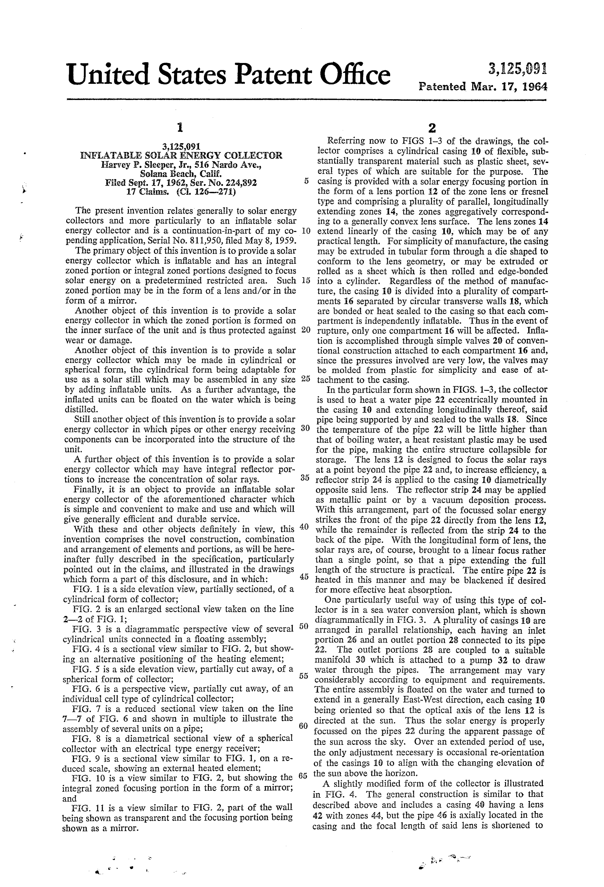
Referring now to FIGS 1-3 of the drawings, the col
NFLATABLE SOLAR ENERGY COLLECTOR lector comprises a cylindrical casing 10 of flexible, sub Harvey P. Sleeper, Jr., 516 Nardo Ave., Stantially transparent material such as plastic sheet, sev Soiana Beach, Caif. eral types of which are suitable for the purpose. The
Filed Sept. 7, 1962, Ser. No. 224,892 casing is provided with a solar energy focusing portion in s 17 Claims. (C. 126-275) the form of a lens portion 2 of the zone lens or fresnel type and comprising a plurality of parallel, longitudinally
The present invention relates generally to solar energy extending Zones 14, the Zones aggregatively correspond collectors and more particularly to an inflatable solar ing to a generally convex lens surface. The lens zones 14 energy collector and is a continuation-in-part of my co IO extend linearly of the casing 10, which may be of any pending application, Serial No. 811,950, filed May 8, 1959. practical length. For simplicity of manufacture, the casing The primary object of this invention is to provide a solar may be extruded in tubular form through a die shaped to energy collector which is inflatable and has an integral conform to the lens geometry, or may be extruded or Zoned portion or integral zoned portions designed to focus rolled as a sheet which is then rolled and edge-bonded Solar energy on a predetermined restricted area. Such 5 into a cylinder. Regardless of the method of manufac Zoned portion may be in the form of a lens and/or in the ture, the casing it is divided into a plurality of compart form of a mirror. ments 16 separated by circular transverse walls 18, which Another object of this invention is to provide a solar are bonded or heat sealed to the casing so that each com energy collector in which the zoned portion is formed on partment is independently inflatable. Thus in the event of the inner surface of the unit and is thus protected against 20 rupture, only one compartment 6 will be affected. Infa Wear or damage. tion is accomplished through simple valves 20 of conven Another object of this invention is to provide a solar tional construction attached to each compartment 16 and, energy collector which may be made in cylindrical or since the pressures involved are very low, the valves may spherical form, the cylindrical form being adaptable for be molded from plastic for simplicity and ease of at use as a solar still which may be assembled in any size 25 tachment to the casing.
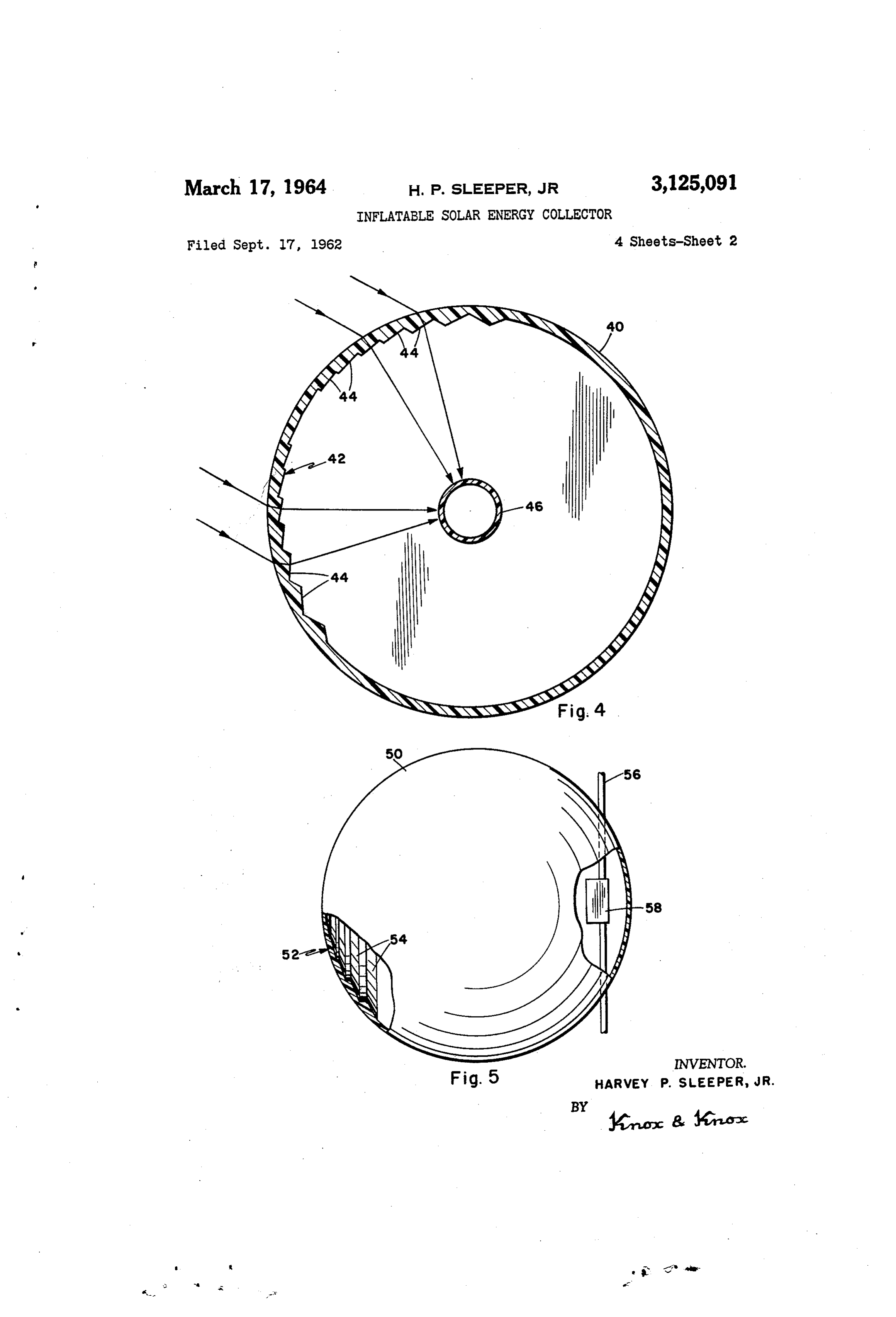
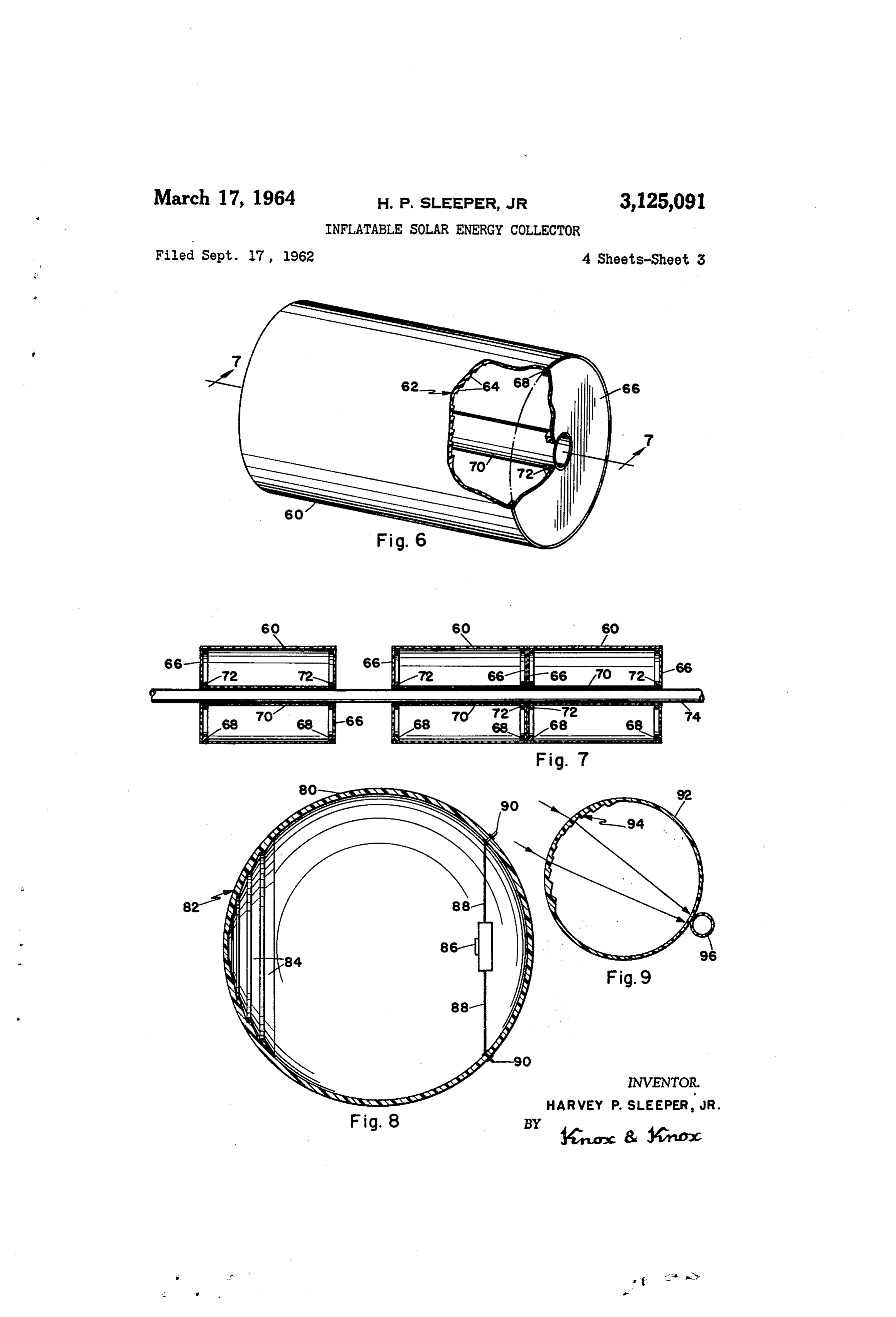
by adding inflatable units. As a further advantage, the In the particular form shown in FIGS. 1-3, the collector inflated units can be floated on the water which is being is used to heat a water pipe 22 eccentrically mounted in distilled. the casing 10 and extending longitudinally thereof, said Still another object of this invention is to provide a solar pipe being supported by and sealed to the walls 18. Since energy collector in which pipes or other energy receiving 30 the temperature of the pipe 22 will be little higher than components can be incorporated into the structure of the that of boiling water, a heat resistant plastic may be used unit. for the pipe, making the entire structure collapsible for A further object of this invention is to provide a solar storage. The lens 2 is designed to focus the solar rays energy collector which may have integral reflector por at a point beyond the pipe 22 and, to increase efficiency, a tions to increase the concentration of solar rays. 35 reflector strip 24 is applied to the casing 10 diametrically Finally, it is an object to provide an inflatable solar opposite said lens. The reflector strip 24 may be applied energy collector of the aforementioned character which as metallic paint or by a vacuum deposition process. is simple and convenient to make and use and which will With this arrangement, part of the focussed solar energy give generally efficient and durable service. Strikes the front of the pipe 22 directly from the lens 12, With these and other objects definitely in view, this 40 while the remainder is reflected from the strip 24 to the invention comprises the novel construction, combination back of the pipe. With the longitudinal form of lens, the and arrangement of elements and portions, as will be here Solar rays are, of course, brought to a linear focus rather inafter fully described in the specification, particularly than a single point, so that a pipe extending the full pointed out in the claims, and illustrated in the drawings 45 length of the structure is practical. The entire pipe 22 is which fortin a part of this disclosure, and in which: heated in this manner and may be blackened if desired F.G. 1 is a side elevation view, partially sectioned, of a for more effective heat absorption. cylindrical form of collector; One particularly useful way of using this type of col F.G. 2 is an enlarged sectional view taken on the line lector is in a sea water conversion plant, which is shown 2-2 of FIG. 1; diagrammatically in FG. 3. A plurality of casings e are FIG. 3 is a diagrammatic perspective view of several arranged in parallel relationship, each having an inlet cylindrical units connected in a floating assembly; portion 26 and an outlet portion 28 connected to its pipe FIG. 4 is a sectional view similar to FIG. 2, but show 22. The outlet portions 28 are coupled to a suitable ing an alternative positioning of the heating element; manifold 30 which is attached to a pump 32 to draw FIG. 5 is a side elevation view, partially cut away, of a 55 Water through the pipes. The arrangement may vary spherical form of collector; considerably according to equipment and requirements. FIG. 6 is a perspective view, partially cut away, of an The entire assembly is floated on the water and turned to individual cell type of cylindrical collector; extend in a generally East-West direction, each casing 10 FG. 7 is a reduced sectional view taken on the line being oriented so that the optical axis of the lens 12 is 7 7 of FIG. 6 and shown in multiple to illustrate the 60 directed at the Sun. Thus the Solar energy is properly assembly of several units on a pipe; focussed on the pipes 22 during the apparent passage of FIG. 8 is a diametrical sectional view of a spherical the sun across the sky. Over an extended period of use, collector with an electrical type energy receiver; the only adjustment necessary is occasional re-orientation F.G. 9 is a sectional view similai to FG. 1, on a re of the casings 3 to align with the changing elevation of duced scale, showing an external heated element; 65 the sun above the horizon.
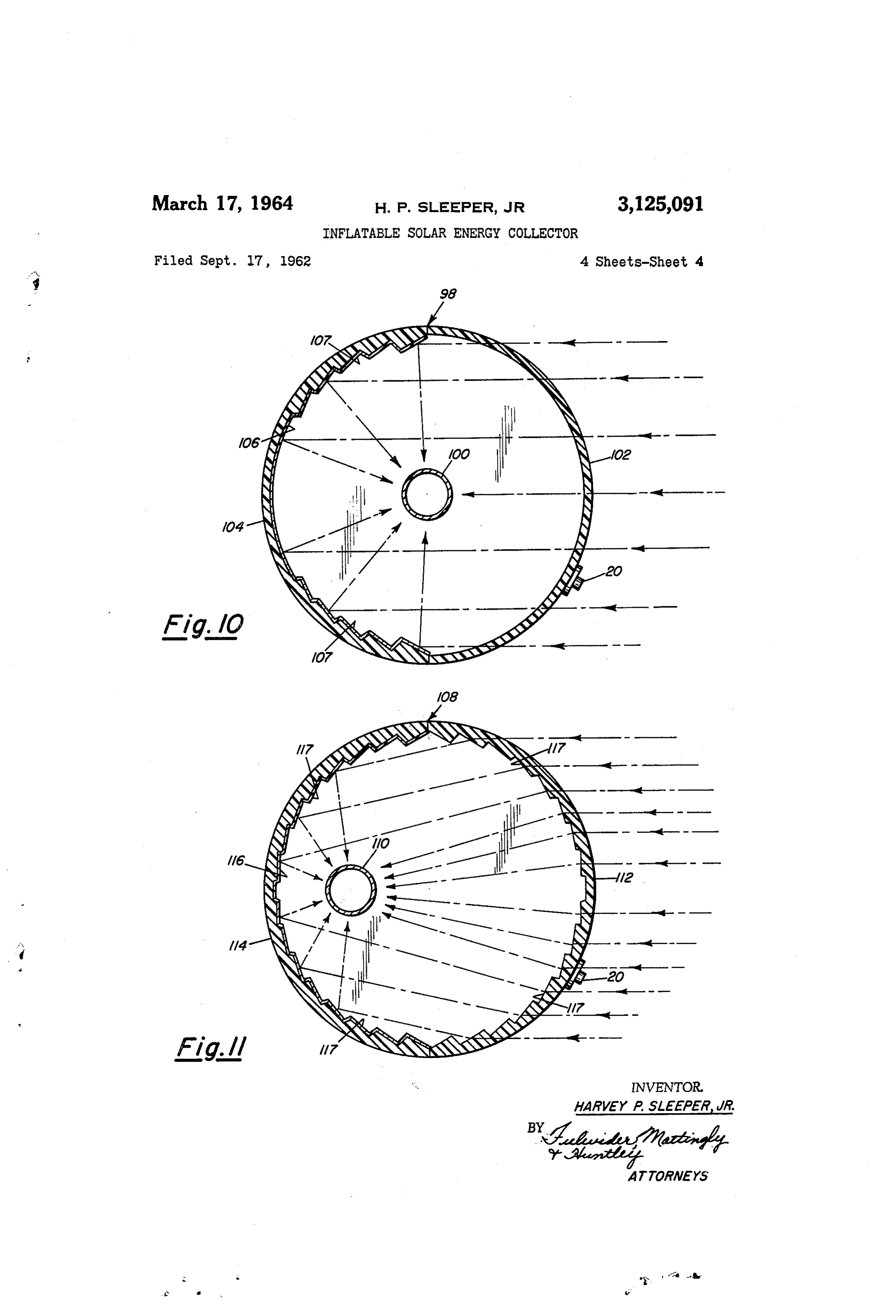
FIG. 10 is a view similar to FIG. 2, but showing the integral zoned focusing portion in the form of a mirror; in AF.G. slightly modified form of the collector is illustrated 4. The general construction is similar to that and
FIG. 11 is a view similar to FIG. 2, part of the wall described above and includes a casing 40 having a lens being shown as transparent and the focusing portion being 42 with zones 44, but the pipe 46 is axially located in the shown as a mirror. casing and the focal length of said lens is shortened to
Page 6
s 4.
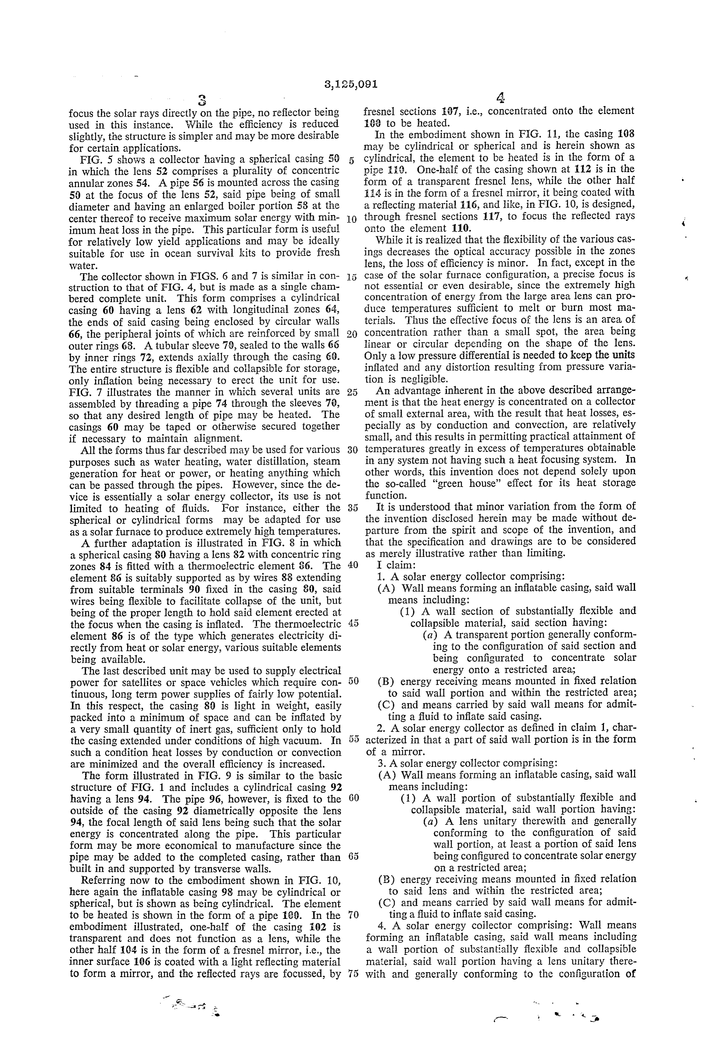
focus the solar rays directly on the pipe, no reflector being fresnel sections 07, i.e., concentrated onto the element used in this instance. While the efficiency is reduced 109 to be heated.
slightly, the structure is simpler and may be more desirable In the embodiment shown in FIG. 11, the casing 108 for certain applications. may be cylindrical or spherical and is herein shown as FIG. 5 shows a collector having a spherical casing 50 5 cylindrical, the element to be heated is in the form of a in which the lens 52 comprises a plurality of concentric pipe it. One-half of the casing shown at 12 is in the annular zones 54. A pipe 56 is mounted across the casing form of a transparent fresnel lens, while the other half 50 at the focus of the lens 52, said pipe being of smail 124 is in the form of a fresnel mirror, it being coated with diameter and having an enlarged boiler portion 58 at the a reflecting material 16, and like, in FIG. 10, is designed, center thereof to receive maximum solar energy with min IO through fresnel sections 117, to focus the reflected rays imum heat loss in the pipe. This particular form is useful onto the element 10.
for relatively low yield applications and may be ideally While it is realized that the flexibility of the various cas suitable for use in ocean survival kits to provide fresh ings decreases the optical accuracy possible in the zones Water. lens, the loss of efficiency is minor. In fact, except in the The collector shown in FIGS. 6 and 7 is similar in con case of the solar furnace configuration, a precise focus is struction to that of FIG. 4, but is made as a single cham not essential or even desirable, since the extremely high bered complete unit. This form comprises a cylindrical concentration of energy from the large area lens can pro casing 60 having a lens 62 with longitudinal zones 64, duce temperatures sufficient to melt or burn most ma the ends of said casing being enclosed by circular walls terials. Thus the effective focus of the lens is an area of 66, the peripheral joints of which are reinforced by small concentration rather than a small spot, the area being outer rings 68. A tubular sleeve 79, sealed to the walls 66 linear or circular depending on the shape of the lens. by inner rings 72, extends axially through the casing 60. Only a low pressure differential is needed to keep the units The entire structure is flexible and collapsible for storage, inflated and any distortion resulting from pressure varia only inflation being necessary to erect the unit for use. tion is negligible.
FIG. 7 illustrates the manner in which several units are 25 An advantage inherent in the above described arrange assembled by threading a pipe 74 through the sleeves 70, ment is that the heat energy is concentrated on a collector so that any desired length of pipe may be heated. The of small external area, with the result that heat losses, es casings 60 may be taped or otherwise secured together pecially as by conduction and convection, are relatively if necessary to maintain alignment. small, and this results in permitting practical attainment of All the forms thus far described may be used for various 30 temperatures greatly in excess of temperatures obtainable purposes such as water heating, water distillation, steam in any system not having such a heat focusing system. In generation for heat or power, or heating anything which other words, this invention does not depend solely upon can be passed through the pipes. However, since the de the so-called "green house' effect for its heat storage vice is essentially a solar energy collector, its use is not function.
limited to heating of fluids. For instance, either the It is understood that minor variation from the form of spherical or cylindrical forms may be adapted for use the invention disclosed herein may be made without de as a solar furnace to produce extremely high temperatures. parture from the spirit and scope of the invention, and A further adaptation is illustrated in FIG. 8 in which that the specification and drawings are to be considered a spherical casing 80 having a lens 82 with concentric ring as merely illustrative rather than limiting. zones 84 is fitted with a thermoelectric element 86. The 40 I claim:
element 86 is suitably supported as by wires 88 extending 1. A solar energy collector comprising: from suitable terminals 90 fixed in the casing 80, said (A) Wall means forming an inflatable casing, said wall wires being flexible to facilitate collapse of the unit, but means including:
being of the proper length to hold said element erected at (1) A wall section of substantially flexible and the focus when the casing is inflated. The thermoelectric collapsible material, said section having: element 86 is of the type which generates electricity di (a) A transparent portion generally conform rectly from heat or solar energy, various suitable elements ing to the configuration of said section and being available. being configurated to concentrate solar The last described unit may be used to supply electrical energy onto a restricted area; power for satellites or space vehicles which require con (B) energy receiving means mounted in fixed relation tinuous, long term power supplies of fairly low potential. to said wall portion and within the restricted area; In this respect, the casing 80 is light in weight, easily (C) and means carried by said wall means for admit packed into a minimum of space and can be inflated by ting a fluid to inflate said casing. a very Small quantity of inert gas, sufficient only to hold 55 2. A solar energy collector as defined in claim 1, char the casing extended under conditions of high vacuum. In acterized in that a part of said wall portion is in the form Such a condition heat losses by conduction or convection of a mirror.
are minimized and the overall efficiency is increased. 3. A solar energy collector comprising: The form illustrated in FIG. 9 is similar to the basic (A) Wall means forming an inflatable casing, said wall structure of FIG. 1 and includes a cylindrical casing 92 means including:
having a lens 94. The pipe 96, however, is fixed to the 60 (1) A wall portion of substantially flexible and outside of the casing 92 diametrically opposite the lens collapsible material, said wall portion having: 94, the focal length of said lens being such that the solar (a) A lens unitary therewith and generally energy is concentrated along the pipe. This particular conforming to the configuration of said form may be more economical to manufacture since the wall portion, at least a portion of said lens pipe may be added to the completed casing, rather than being configured to concentrate solar energy built in and supported by transverse walls. on a restricted area; Referring now to the embodiment shown in FIG. 10, (B) energy receiving means mounted in fixed relation here again the inflatable casing 98 may be cylindrical or to said lens and within the restricted area; Spherical, but is shown as being cylindrical. The element (C) and means carried by said wall means for admit to be heated is shown in the form of a pipe 100. In the 70 ting a fluid to inflate said casing. 4. A solar energy collector comprising: Wall means embodiment illustrated, one-half of the casing 102 is forming transparent and does not function as a lens, while the an inflatable casing, said wall means including other half 104 is in the form of a fresnel mirror, i.e., the a wall portion of substantially flexible and collapsible inner Surface 106 is coated with a light reflecting material material, said wali portion having a lens unitary there to form a mirror, and the reflected rays are focussed, by 75 With and generally conforming to the configuration of
Page 7
S. 6 said wall portion, said lens being configured to concen 11. A solar energy collector comprising: Wall means trate Solar energy on a restricted area; energy receiving forming an elongated, generally cylindrical, and inflata means mounted in fixed relation to said lens and within ble casing, said wall means including a plurality of trans said restricted area; and means carried by said wall means verse walls providing a plurality of chambers in said cas for admitting a fluid to inflate said casing. 5 ing, said wall means further including a wall portion of 5. A Solar energy collector comprising: Wall means substantially flexible and collapsible material, said wall forming an inflatable casing, said wall means including portion having a lens unitary therewith and generally con a Wall portion of substantially flexible and collapsible forming to the configuration of said wall portion, said material, said wall portion having a lens unitary there lens having a plurality of generally parallel, longitudinal With and generally conforming to the configuration of O ly extending Zones configured to concentrate solar energy said wall portion, said lens having a plurality of generally on an elongated restricted area; energy receiving means parallel Zones configured to concentrate solar energy on arranged in elongated form generally parallel to said a restricted area; energy receiving means arranged in Zones and mounted in fixed relation to said lens and elongated form generally parallel to said zones and within said restricted area, and extending longitudinally mounted in fixed relation to said lens and within said 5 through said casing and said plurality of transverse walls; restricted area; and means carried by said wall means for and means carried by said wall means adjacent each said admitting a fluid to inflate said casing. chamber for admitting a fluid to independently inflate 6. A solar energy collector comprising: Wall means each said chamber.
forming an inflatable casing, said wall means including a 12. A solar energy collector comprising: Wall means Wall portion of substantially flexible and collapsible ma 20 forming an elongated, generally cylindrical, and inflat terial, said wall portion having a lens unitary therewith able casing, said wall means including a plurality of trans and generally conforming to the configuration of said verse walls providing a plurality of chambers in said cas wall portion, said lens having a plurality of generally ing, said wall means further including a wall portion of parallel Zones configured to concentrate solar energy on substantially flexible and collapsible material, said wall a restricted area; a fluid conducting member extending 25 portion having a lens unitary therewith and generally con through said casing and traversing said restricted area; forming to the configuration of said wall portion, said and means carried by said wall means for admitting a lens having a plurality of generally parallel, longitudinal gas to inflate said casing. ly extending Zones configured to concentrate solar energy 7. A Solar energy collector comprising: Wall means on an elongated restricted area; energy receiving means forming an inflatable casing, said wall means including a 30 arranged in elongated form generally parallel to said wall portion of substantially flexible and collapsible ma Zones and mounted in fixed relation to said lens and terial, said Wall portion having a lens unitary therewith within said restricted area, said energy receiving means and generally conforming to the configuration of said extending longitudinally through said plurality of trans Wall portion, said lens having a plurality of generally par verse walls, and supported by said plurality of transverse allel Zones configured to concentrate solar energy on a walls upon inflation of said casing; and means carried by restricted area; a fluid conducting member extending said wall means adjacent each said chamber for admitting through said casing and traversing said restricted area; a a gas to independently inflate each said chamber. reflector surface in fixed relation to said lens and dis 13. A solar energy collector comprising: An in posed adjacent said member to reflect a portion of the flatable casing of substantially flexible material having a Solar energy from said lens onto said member; and means 40 lens unitary with a portion of said casing and conform carried by said wall means for admitting a fluid to inflate ing to the configuration of said portion, said lens being said casing. configured to concentrate solar energy on a restricted 8. A solar energy collector comprising: Wall means area; energy receiving means mounted in fixed relation forming a double-ended, elongated, generally cylindrical, to said lens and within said restricted area; and means and inflatable casing, said wall means including a wall 45 carried by said casing for admitting a fluid to inflate said portion of substantially flexible and collapsible material, casing.
said Wall portion having a zoned lens of the fresnel type 14. A solar energy collector comprising: Wall means unitary therewith and generally conforming to the con forming an inflatable casing, said wall means including figuration of said wall portion, said lens having a plurality a Wall portion of substantially flexible material, said wall of parallel, longitudinally extending zones configured to portion including a lens unitary therewith and supported concentrate solar energy on an elongated restricted area; by said wall portion upon inflation of said casing, said a fluid conducting pipe arranged generally parallel to said lens being configured to concentrate solar energy on a Zones, and mounted in fixed relation to said lens and restricted area; energy receiving means mounted in fixed within said restricted area; and means carried by said relation to said lens and within said restricted area; and wall means for admitting a fluid to inflate said casing. 55. means carried by said casing for admitting a fluid to in 9. A solar energy collector according to claim 8 where flate said casing.
in said pipe transverses the length of said casing along 15. A solar energy collector comprising: the axis of said casing. (A) Wall means forming an inflatable casing, said 10. A solar energy collector comprising: Wall means wall means including:
forming an elongated, generally cylindrical, and inflatable (1) A wall section of substantially flexible and casing, said wall means including a wall portion of sub 60 collapsible material, said section having:
stantially flexible and collapsible material, said wall por (a) a mirror portion generally conforming tion having a lens unitary therewith and generally con With the configuration of said section and forming to the configuration of said wall portion, said being configured to concentrate solar ener lens having a plurality of parallel, longitudinally extend gy onto a restricted area; ing zones configured to concentrate solar energy on an 65 (b) a transparent portion in the form of a elongated restricted area; elongated energy receiving fresnel lens disposed to focus, in conjunc means mounted in fixed relation to said lens along an tion with the mirror, concentrated solar axis parallel to and spaced from the axis of said casing, energy onto said restricted area; and within said restricted area; a reflector surface fixed (B) energy receiving means mounted in fixed relation to said wall portion in opposed relation to said lens to 70 direct a portion of the solar energy onto said energy re to said wall portions, and within the restricted area; ceiving means, said reflector surface being supported in (C) and means carried by said wall means for admit said opposed relation by said wall portion upon inflation ting a fluid to inflate said casing. of said casing; and means carried by said casing for ad 16. A solar energy collector as defined in claim 15, mitting a fluid to inflate said casing. 75 characterized in that the mirror is of the fresnel type.
Page 8
17. A solar energy collector comprising: References Cited in the file of this patent (A) A wall section of substantially flexible and col UNITED STATES PATENTS lapsible material, said section having: 2,427,262 Delano --------------- Sept. 9, 1947 (a) a portion in the form of a fresnel mirror 2,455,834 Ushakoff ------------- Dec. 7, 1948 generally conforming with the configuration of 2,798,478 Tarcici --------------- July 9, 1957 said section and being configured to concen trate solar energy onto a restricted area; 2,872,915
(b) a lens portion disposed to focus, in conjunc 3,054,328 Rodgers -------------- Sept. 18, 1962 tion with the fresnel mirror, concentrated solar energy onto said restricted area; IO FOREIGN PATENTS (B) energy receiving means mounted in fixed relation 131,069 Australia ------------- Jan. 21, 1949 to said wall portions, and within the restricted area;
(C) and means carried by said wall means for admit ting a fluid to inflate said casing.

Provenance
- Collection
- Cited prior art
- Original PDF
- patentimages.storage.googleapis.com →
- Pages
- 8
- Method
- pdftotext (the PDF's own text layer) + pdftoppm 300dpi page scans
- Source
- Google Patents bibliographic record
- Granted
- 1964-03-17
- Transcribed from
- patentimages.storage.googleapis.com →