patent · US4181100
Internal combustion engine operated on injected fuel supplemented with hydrogen
1 January 1980
Page 1 — bibliographic record
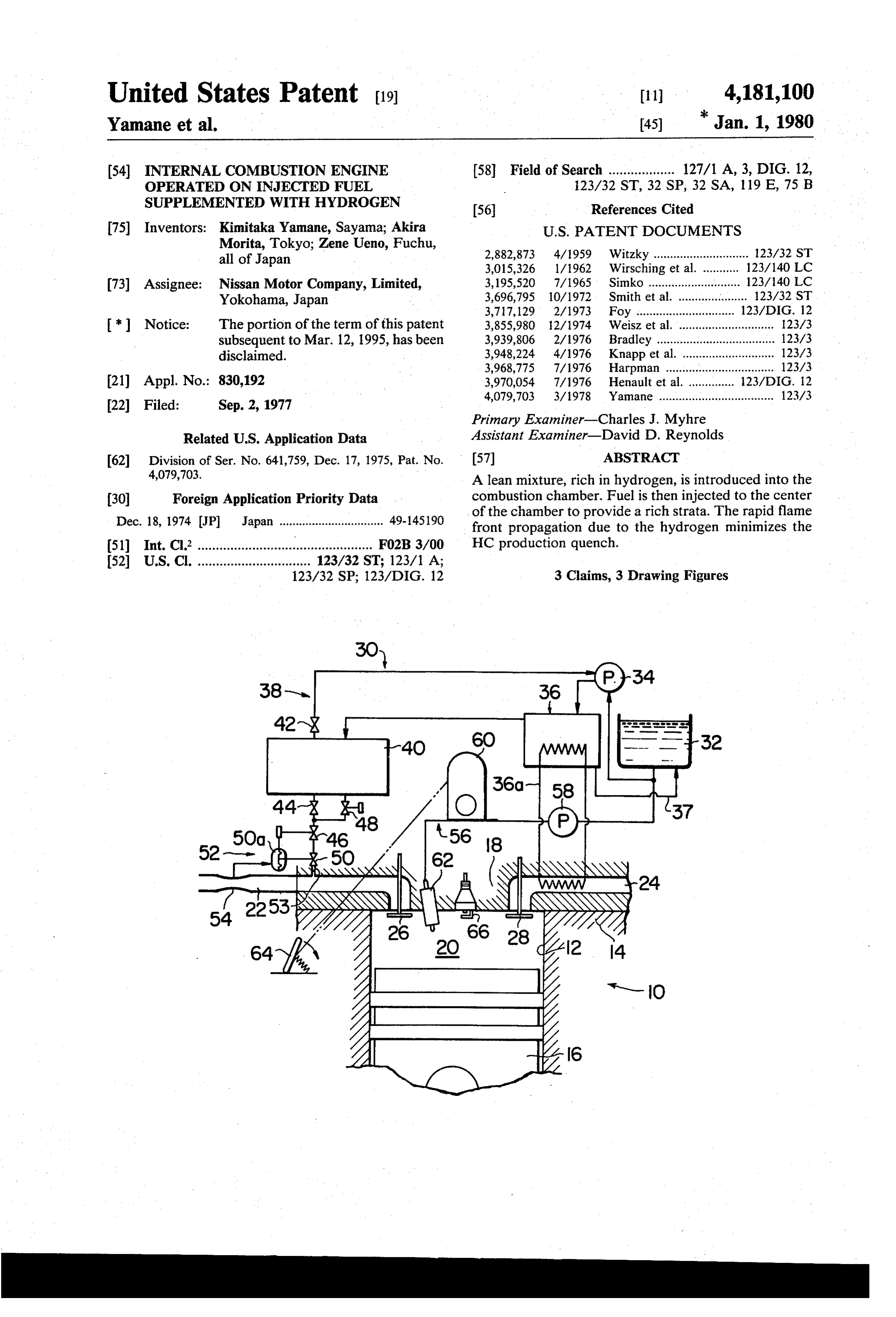
United States Patent (19) 11) 4,181,100 Yamane et al. (45) "Jan. 1, 1980 54 INTERNAL COMBUSTION ENGINE 58 Field of Search .................. 127/1 A, 3, DIG. 12, OPERATED ON N.JECTED FUEL 123/32 ST, 32 SP, 32 SA, 119 E, 75 B SUPPLEMENTED WITH HYDROGEN 56 - References Cited 75) Inventors: Kimitaka Yamane, Sayama; Akira U.S. PATENT DOCUMENTS Morita, Tokyo; Zene Ueno, Fuchu, 2,882,873 4/1959 Witzky ............................. 123/32 ST all of Japan 3,015,326 1/1962 Wirsching et al. ... 123/140 LC 73) Assignee: Nissan Motor Company, Limited, 3, 195,520 7/1965 Simko ............................ 123/140 C Yokohama, Japan 3,696,795 10/1972 Smith et al. ..................... 123/32. ST 3,717, 129 2/1973 Foy ................ ... 123/DIG. 12 * Notice: The portion of the term of this patent 3,855,980 12/1974 Weisz et al. ............................. 123/3 subsequent to Mar. 12, 1995, has been 3,939,806 2/1976 Bradley ......... ... 123/3 disclaimed. 3,948,224 4/1976 Knapp et al. . ... 123/3 3,968,775 7/1976 Harpman ................................. 123/3 (21) Appl. No.: 830,192 3,970,054 7/1976 Henault et al. ... ... 23/DIG. 12 4,079,703 3/1978 Yamane ................................... 123/3
Primary Examiner-Charles J. Myhre
Related U.S. Application Data Assistant Examiner-David D. Reynolds 62 Division of Ser. No. 641,759, Dec. 17, 1975, Pat. No. (57) ABSTRACT 4,079,703. A lean mixture, rich in hydrogen, is introduced into the 30 Foreign Application Priority Data combustion chamber. Fuel is then injected to the center Dec. 18, 1974 JP Japan ................................ 49-145190 of the chamber to provide a rich strata. The rapid flame front propagation due to the hydrogen minimizes the (51) Int. Cl? .............................................. F02B3/00 HC production quench.
52 U.S. Cl. ............................... 123/32. ST; 123/1 A;
123/32 SP; 123/DIG. 12 3 Claims, 3 Drawing Figures
64As 2 4
Page 2
Drawing sheet — no readable text.
Page 3
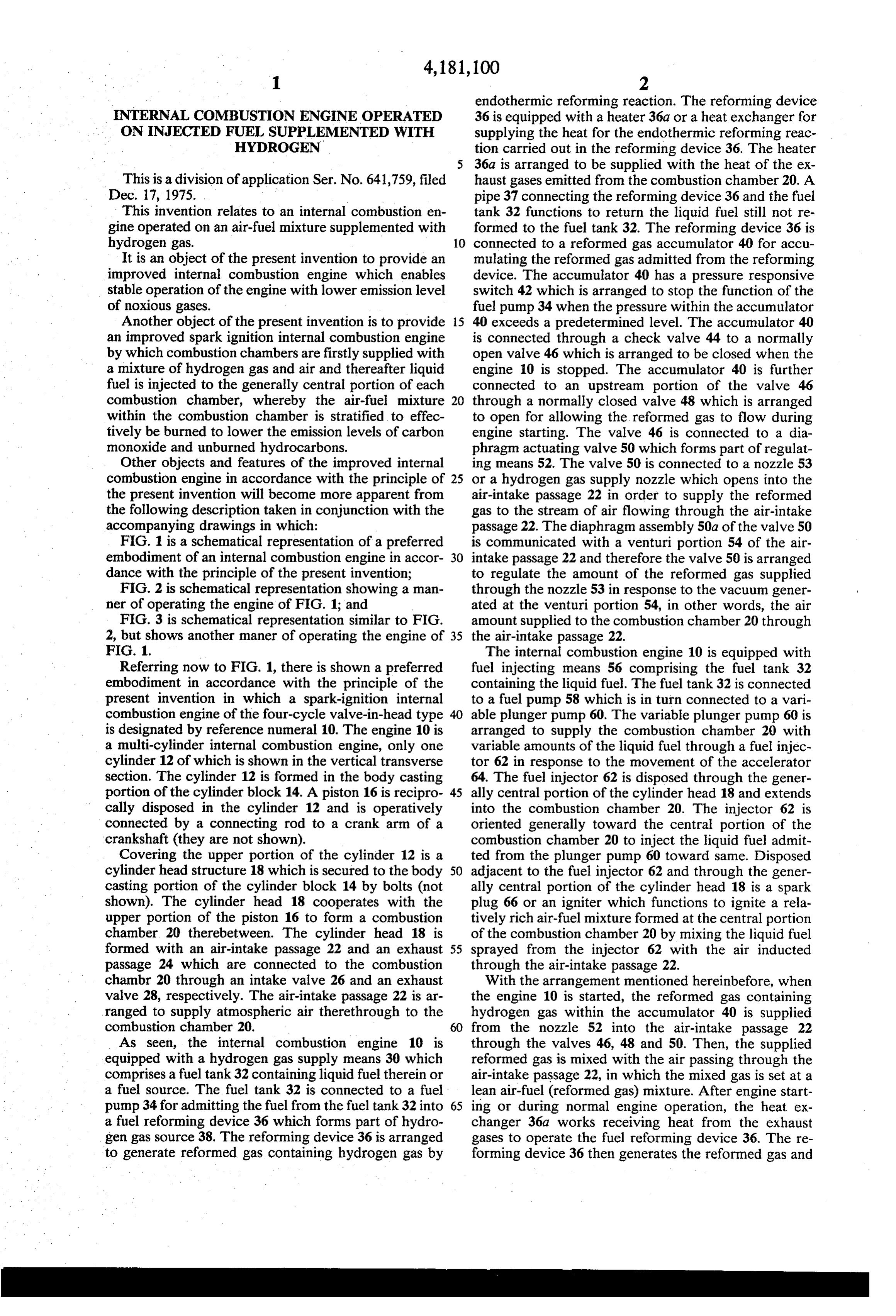
endothermic reforming reaction. The reforming device
INTERNAL COMBUSTION ENGINE OPERATED 36 is equipped with a heater 36a or a heat exchanger for ON INJECTED FUEL SUPPLEMENTED WITH supplying the heat for the endothermic reforming reac HYDROGEN tion carried out in the reforming device 36. The heater 36a is arranged to be supplied with the heat of the ex
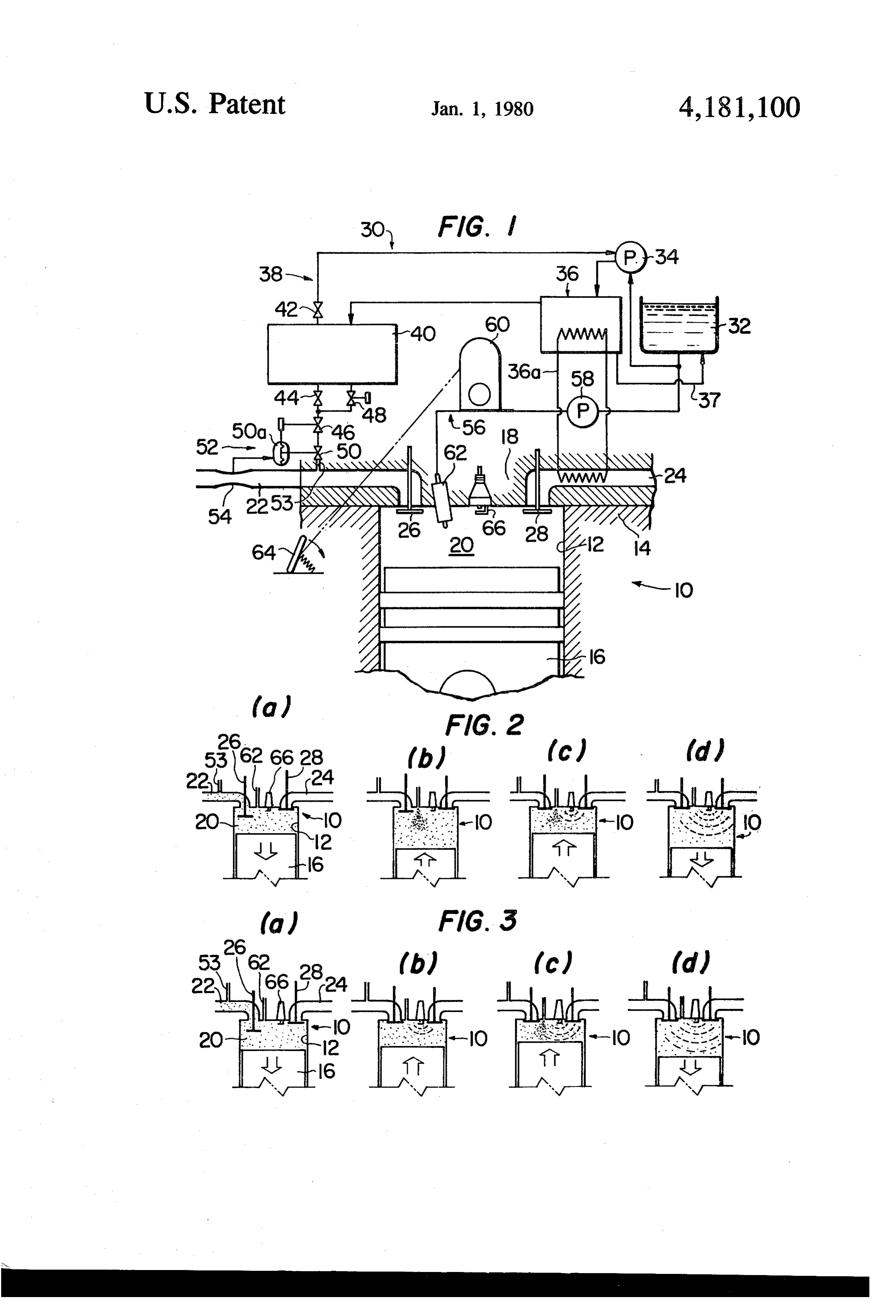
This is a division of application Ser. No. 641,759, filed haust gases emitted from the combustion chamber 20. A Dec. 17, 1975. pipe 37 connecting the reforming device 36 and the fuel This invention relates to an internal combustion en tank 32 functions to return the liquid fuel still not re gine operated on an air-fuel mixture supplemented with formed to the fuel tank 32. The reforming device 36 is hydrogen gas. 10 connected to a reformed gas accumulator 40 for accu It is an object of the present invention to provide an mulating the reformed gas admitted from the reforming improved internal combustion engine which enables device. The accumulator 40 has a pressure responsive stable operation of the engine with lower emission level switch 42 which is arranged to stop the function of the of noxious gases. fuel pump 34 when the pressure within the accumulator Another object of the present invention is to provide 15 40 exceeds a predetermined level. The accumulator 40 an improved spark ignition internal combustion engine is connected through a check valve 44 to a normally by which combustion chambers are firstly supplied with open valve 46 which is arranged to be closed when the a mixture of hydrogen gas and air and thereafter liquid engine 10 is stopped. The accumulator 40 is further fuel is injected to the generally central portion of each connected to an upstream portion of the valve 46 combustion chamber, whereby the air-fuel mixture 20 through a normally closed valve 48 which is arranged within the combustion chamber is stratified to effec to open for allowing the reformed gas to flow during tively be burned to lower the emission levels of carbon engine starting. The valve 46 is connected to a dia monoxide and unburned hydrocarbons. phragm actuating valve 50 which forms part of regulat Other objects and features of the improved internal ing means 52. The valve 50 is connected to a nozzle 53 combustion engine in accordance with the principle of 25 or a hydrogen gas supply nozzle which opens into the the present invention will become more apparent from air-intake passage 22 in order to supply the reformed the following description taken in conjunction with the gas to the stream of air flowing through the air-intake accompanying drawings in which: passage 22. The diaphragm assembly 50a of the valve 50 FIG. 1 is a schematical representation of a preferred is communicated with a venturi portion 54 of the air embodiment of an internal combustion engine in accor 30 intake passage 22 and therefore the valve 50 is arranged dance with the principle of the present invention; to regulate the amount of the reformed gas supplied FIG. 2 is schematical representation showing a man through the nozzle 53 in response to the vacuum gener ner of operating the engine of FIG. 1; and ated at the venturi portion 54, in other words, the air FIG. 3 is schematical representation similar to FIG. amount supplied to the combustion chamber 20 through 2, but shows another maner of operating the engine of 35 the air-intake passage 22.
FIG. 1. The internal combustion engine 10 is equipped with Referring now to FIG. 1, there is shown a preferred fuel injecting means 56 comprising the fuel tank 32 embodiment in accordance with the principle of the containing the liquid fuel. The fuel tank 32 is connected present invention in which a spark-ignition internal to a fuel pump 58 which is in turn connected to a vari combustion engine of the four-cycle valve-in-head type able plunger pump 60. The variable plunger pump 60 is is designated by reference numeral 10. The engine 10 is arranged to supply the combustion chamber 20 with a multi-cylinder internal combustion engine, only one variable amounts of the liquid fuel through a fuel injec cylinder 12 of which is shown in the vertical transverse tor 62 in response to the movement of the accelerator section. The cylinder 12 is formed in the body casting 64. The fuel injector 62 is disposed through the gener portion of the cylinder block 14. A piston 16 is recipro 45 ally central portion of the cylinder head 18 and extends cally disposed in the cylinder 12 and is operatively into the combustion chamber 20. The injector 62 is connected by a connecting rod to a crank arm of a oriented generally toward the central portion of the crankshaft (they are not shown). combustion chamber 20 to inject the liquid fuel admit Covering the upper portion of the cylinder 12 is a ted from the plunger pump 60 toward same. Disposed cylinder head structure 18 which is secured to the body 50 adjacent to the fuel injector 62 and through the gener casting portion of the cylinder block 14 by bolts (not ally central portion of the cylinder head 18 is a spark shown). The cylinder head 18 cooperates with the plug 66 or an igniter which functions to ignite a rela upper portion of the piston 16 to form a combustion tively rich air-fuel mixture formed at the central portion chamber 20 therebetween. The cylinder head 18 is of the combustion chamber 20 by mixing the liquid fuel formed with an air-intake passage 22 and an exhaust 55 sprayed from the injector 62 with the air inducted passage 24 which are connected to the combustion through the air-intake passage 22.
chambr 20 through an intake valve 26 and an exhaust With the arrangement mentioned hereinbefore, when valve 28, respectively. The air-intake passage 22 is ar the engine 10 is started, the reformed gas containing ranged to supply atmospheric air therethrough to the hydrogen gas within the accumulator 40 is supplied combustion chamber 20. 60 from the nozzle 52 into the air-intake passage 22 As seen, the internal combustion engine 10 is through the valves 46, 48 and 50. Then, the supplied equipped with a hydrogen gas supply means 30 which reformed gas is mixed with the air passing through the comprises a fuel tank 32 containing liquid fuel therein or air-intake passage 22, in which the mixed gas is set at a a fuel source. The fuel tank 32 is connected to a fuel lean air-fuel (reformed gas) mixture. After engine start pump 34 for admitting the fuel from the fuel tank 32 into 65 ing or during normal engine operation, the heat ex a fuel reforming device 36 which forms part of hydro changer 36a works receiving heat from the exhaust gen gas source 38. The reforming device 36 is arranged gases to operate the fuel reforming device 36. The re to generate reformed gas containing hydrogen gas by forming device 36 then generates the reformed gas and
Page 4
the reformed gas is admitted to the accusnulator 40. The mixture is achieved and therefore ignition and combus reformed gas is thereafter supplied through the valves tion of the air-fuel mixture are effectively carried out 44, 46 and 50 from the nozzle 52 into the air-intake even if the air-fuel mixture is as a whole over lean, and passage 22 to mix with the air passing through the air thermal efficiency of the engine is as a matter of course intake passage 22. improved. In addition, since the air-fuel mixture adja FIG. 2 illustrates a manner of operation of the engine cent the inner wall surface of the combustion chamber 10 constructed in accordance with the present inven contains hydrogen gas, the air-fuel mixture is effectively tion, at position (a) of which the mixed gas of reformed burned to prevent the incomplete combustion and ac gas and air in the air-intake passage 22 is thereafter cordingly the emission levels of carbon monoxide and sucked and supplied through the intake valve 26 into 10 unburned hydrocarbons are lowered to a considerable the combustion chamber 20 by descent of the piston 16 extent.
or during suction or induction stroke of the engine 10. What is claimed is:
At position (b), the liquid fuel is injected or sprayed 1. An internal combustion engine having a cylinder, a from the injector 62 to the generally central portion of cylinder head and a piston reciprocally disposed in the the combustion chamber 20 during the compression 15 cylinder to stroke. In this state, the relatively rich air-fuel mixture the cylinderdefinehead, a combustion chamber between it and comprising:
containing hydrogen gas is formed at the generally an air-intake passage fluidly connected to the com central portion of the combustion chamber 20 and a bustion chamber to supply air therethrough to the layer of relatively lean air-fuel mixture containing hy combustion chamber;
drogen gas is formed around the rich air-fuel mixture. 20 hydrogen gas supply means for supplying hydrogen At position (c), the mixture compressed by the piston 16 gas into said air-intake passage in response to the is then ignited by the spark plug 66, in which the spark amount of the air supplied to the combustion cham plug 66 ignites the rich air-fuel mixture at the central ber;
portion of the combustion chamber 20 to secure the ignition of the entire air-fuel mixture. At position (d), 25 a fuel injector for injecting liquid fuel to the central combustion spreads to the layer of lean air-fuel mixture portion of the combustion chamber to form a rich surrounding the rich air-fuel mixture and then the gas air-fuel mixture at the generally central portion of within the combustion chamber expands to cause the the combustion chamber; and piston to descend. It should be noted that the layer of a spark plug disposed through the generally central the mixed gas containing hydrogen gas is adjacent the 30 portion of the cylinder head to ignite the rich air inner wall of the combustion chamber 20 and accord fuel mixture at the generally central portion of the ingly the layer is effectively combusted through the combustion chamber.
layer is of the lean air-fuel mixture. This prevents imper 2. An internal combustion engine having a cylinder, a fect combustion of the lean mixture adjacent the inner cylinder head and a piston reciprocally disposed in the wall surface of the combustion chamber due to the low 35 cylinder to define a combustion chamber between it and calorific value of the lean mixture and release or absorp the cylinder head, comprising:
tion of heat generated by the combustion through the an air-intake passage fluidly connected to the com wall of the combustion chamber. Therefore formation bustion chamber to supply air therethrough to the of the mixture layer containing hydrogen gas at the combustion chamber;
portion adjacent the inner wall of the combustion cham 40 hydrogen gas supply means for supplying hydrogen ber noticeably contributes to lowering emission levels gas into said air-intake passage in response to the of carbon monoxide and unburned hydrocarbons. amount of the air supplied to the combustion cham FIG. 3 illustrates another manner of operation of the ber;
engine 10 which is similar to that of FIG. 2 with the a fuel injector for injecting liquid fuel to the central exception that the liquid fuel is injected from the fuel 45 portion of the combustion chamber to form a rich injector 62 after the mixed gas of reformed gas and air air-fuel mixture at the generally central portion of is ignited by the spark plug 66. As shown at position (b), the combustion chamber;
the mixed gas containing hydrogen gas is ignited at a a spark plug disposed through the generally central timing before top dead center. The ignition timing is portion of the cylinder head to ignite the rich air peferably about 10 before top dead center. At position 50 fuel mixture at the generally central portion of the (c), the liquid fuel is injected and sprayed into the com combustion chamber; and bustion chamber 20 to be ignited with the flame pro means for causing said spark plug to ignite hydrogen duced by the combustion of the mixed gas. gas supplied by said hydrogen gas supply means While the fuel reforming device 36 and its accessories before the liquid fuel is injected from said fuel are shown and described as a hydrogen gas source, it 55 injector into the combustion chamber. will be seen that a cylinder containing hydrogen gas 3. An internal combustion engine having a cylinder, a may be used for the same purpose. cylinder head and a piston reciprocally disposed in the It will be understood that the engine according to the cylinder to define a combustion chamber between it and present invention is, through not shown, equipped with the cylinder head, comprising;
means for setting the spark-ignition timing of the spark 60 an air-intake passage fluidly connected to the com plug 66 after the fuel injection timing of the injector 62 bustion chamber to supply air therethrough to the when operated in the manner shown in FIG. 2, whereas combustion chamber;
with means for setting the timing of the spark-plug 66 hydrogen gas supply means for supplying hydrogen before the timing of the injector 62 when operated in gas into said air-intake passage in response to the the manner shown in FIG. 3. 65 amount of the air supplied to the combustion cham As is apparent from the foregoing discussion, with ber;
the internal combustion engine in accordance with the a fuel injector for injecting liquid fuel to the central present invention, the stratified charge of the air-fuel portion of the combustion chamber to form a rich
Page 5
. - fuel mixture at the generally central portion of the air-fuel mixture at the generally central portion of combustion chamber; and the combustion chamber means for causing said spark plug to ignite the hydro s gen gas supplied by said hydrogen gas supply a spark plug disposed through the generally central means and the liquid fuel injected from said fuel injector.
portion of the cylinder head to ignite the rich air
Provenance
- Collection
- Cited prior art
- Original PDF
- patentimages.storage.googleapis.com →
- Filed
- 1977-09-02
- Pages
- 5
- Method
- pdftotext (the PDF's own text layer) + pdftoppm 300dpi page scans
- Source
- Google Patents bibliographic record
- Granted
- 1980-01-01
- Inventors
- Kimitaka Yamane; Akira Morita; Zene Ueno; Nissan Motor Co Ltd
- Transcribed from
- patentimages.storage.googleapis.com →