patent · US3906913
System for minimizing internal combustion engine pollution emission
23 September 1975
Page 1 — bibliographic record
United States Patent (19) [11] 3,906,913 Rupe (45) Sept. 23, 1975 54 SYSTEM FOR MINIMIZING INTERNAL 2,482,531 9/1949 Young et al................. 123/DIG. 12
COMBUSTION ENGINE POLLUTION
EMISSION
Primary Examiner-Wendell E. Burns 75 Inventor: Jack H. Rupe, Sunland, Calif. Attorney, Agent, or Firm-Lindenberg, Freilich, 73 Assignee: California Institute of Technology, Wasserman, Rosen & Fernandez Pasadena, Calif.
22) Filed: Aug. 10, 1973 (57) ABSTRACT 21 ) Appl. No.: 387,342 A mixing device is provided for an internal combus tion engine which simultaneously atomizes liquid fuel, (52 U.S. Cl....... 123/121; 123/DIG. 12; 12311 19 E; mixes this fuel with an optimal quantity of hydrogen 1231120; 1231198 A and combines this mixture with a prescribed quantity 51 Int. Cl............................................ F02m 3/08 of air. A throttling mechanism controls the fuel deliv 58) Field of Search......... 23/DIG. 12, 19 E, 121, ery to the engine and also limits the fuel to air equiva 123/127, 120, 198 A lence ratio to be predetermined upper bound to in hibit the production of air pollutants and to a lower 56) References Cited bound which is above the lean flammability of the mixture.
UNITED STATES PATENTS
l, l l 2, 188 9, 1914 Atwood ....................... 123/DIG. 12 18 Claims, 8 Drawing Figures
Page 2
Drawing sheet — no readable text.
Page 3
Drawing sheet — no readable text.
Page 4
Drawing sheet — no readable text.
Page 5
DEMAND
------a EQUIVRATIO
r V - FLAMMABILITY 7O / Lly T - W.O.T.
5O O.6 R THROTTLING X / N. REQUIRED FOR m S CONST = mp
DLE FUEL FLOW
ENGINE SPEED, RPM F G. 7
Page 6
Drawing sheet — no readable text.
Page 7
SYSTEM FOR MINIMIZING INTERNAL
COMBUSTON ENGINE POLLUTION EMISSION OBJECTS AND SUMMARY OF THE INVENTION ORIGIN OF THE INVENTION An object of this invention is the provision of an im provement in an internal combustion engine whereby
The invention described herein was made in the per- 5 it will produce substantially no air pollutants. formance of work under a NASA contract and is sub Another object of this invention is the provision of a ject to the provisions of Section 305 of the National hydrogen-fuel-air mixing system which minimizes the Aeronautics and Space Act of 1958, Public Law amount of pollutants produced by an internal combus 85-568 (72 Stat. 435; 42 USC 2457). tion engine over its operating range. O Still another object of the present invention is the
BACKGROUND OF THE INVENTION provision of a system for maintaining a mixture of hy 1. Field of the Invention drogen-fuel and air for an internal combustion engine The present invention relates to a method and means within predetermined boundary limits over the engine for rendering an internal combustion engine substan 15 operating range.
tially air-pollution free, and more particularly to im Yet another object of the invention is the provision provements therein. of a novel and useful fuel-air mixture control for mini 2. Description of the Prior Art mizing the emission of pollutants by an internal com A great deal of investigation has gone into the prob bustion engine.
lem of reducing the pollutants emitted by an internal The foregoing and other objects of the invention may combustion engine which uses a hydrocarbon fuel. It 20 be achieved by providing an induction system for an in has been recognized that carbon monoxide and other ternal combustion engine which uses an internal vari emissions have been found to decrease as the fuel to air able area fuel control valve under throttle control for ratio is made leaner. The fuel to air ratio is also known mixing hydrogen and fuel to maintain predetermined as the 'equivalence ratio' when it is compared to the 25 proportions over the operating range of the engine. A stoichiometric value for that fuel. However, in either throttle override control is used to maintain an upper case as the mixture is made fuel lean, a point is very bound for the mass flow of this mixture relative to any soon reached where the mixture is no longer flamma given air flow over the engine operating range. The air ble. Thus, it appears desirable to have a means to ex a manner flow to the engine is also controlled by the throttle in to assure that the equivalence ratio of the hy tend the equivalence ratio into the ultra lean region still 30 drogen-fuel-air providing flammability, whereby pollutant emissions bounds and to assure mixture is maintained within prescribed from the internal engine may be minimized. Since the gine speeds when minimal combustible mixtures at high en load requirements on the engine are variable, it is also quired. amounts of power are re necessary to control the equivalence ratio of the fuel The novel features of the invention are set forth with air mixture in an engine over the range of load applied, 35 particularity in the appended claims. The invention will within a lean mixture range, if the engine is to operate best be understood from the following description and be substantially pollutant free. when read in conjunction with the accompanying draw A patent to Blumenberg, U.S. Pat. No. 1,379,077, ingS.
teaches passing hydrogen and oxygen gases through a heavy hydrocarbon fuel to facilitate its vaporization. A 40 BRIEF DESCRIPTION OF THE DRAWINGS patent to Ricardo, U.S. Pat. No. 1,520,772, teaches FIG. 1 is a curve illustrating the characteristic corre mixing a fixed amount of hydrogen and a fixed amount lation between specific emissions (NO) and equiva of air with a hydrocarbon fuel whose quantity can be lence ratio for a spark internal combustion engine. varied from zero to a maximum value over the range 45 FIG. 2 is a schematic drawing of an automobile illus from no load to a maximum load. The hydrocarbon and trating placement of the various components of a sys hydrogen are mixed in the absence of air, and then are tem in accordance with this invention. mixed with the air in the piston of the engine. A patent FIG. 3 is a schematic drawing illustrating the layout to Bogan, U.S. Pat. No. 3,653,364, teaches how to pro tion. of an induction system, in accordance with this inven duce hydrogen gas and then introduce it into the intake 50 manifold below the carburetor to be mixed with fuel FIG. 4 is a drawing of a fuel flow control valve which is in the induction system together with the override and air. The hydrogen gas is for the purpose of provid control.
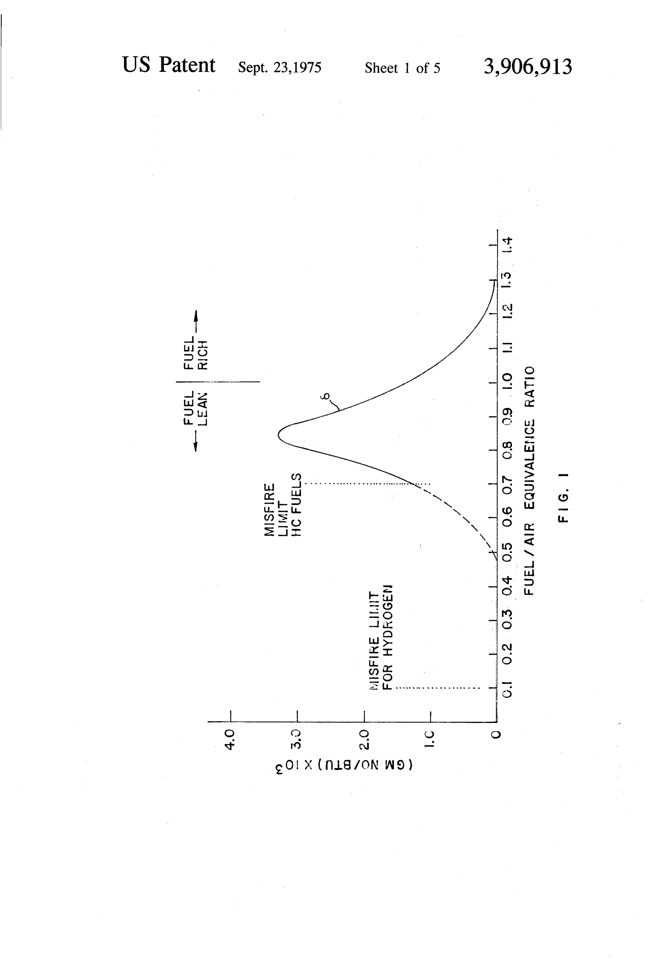
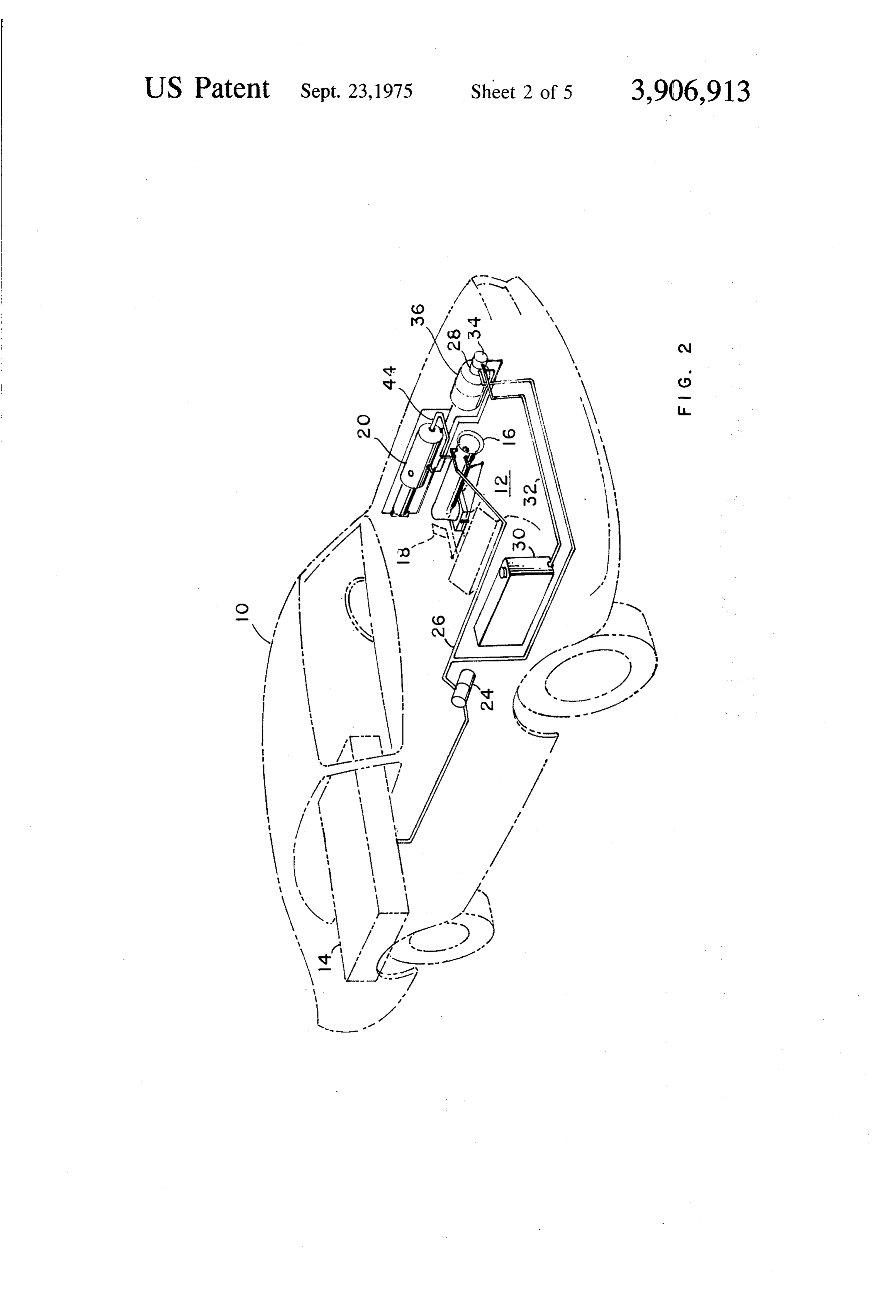
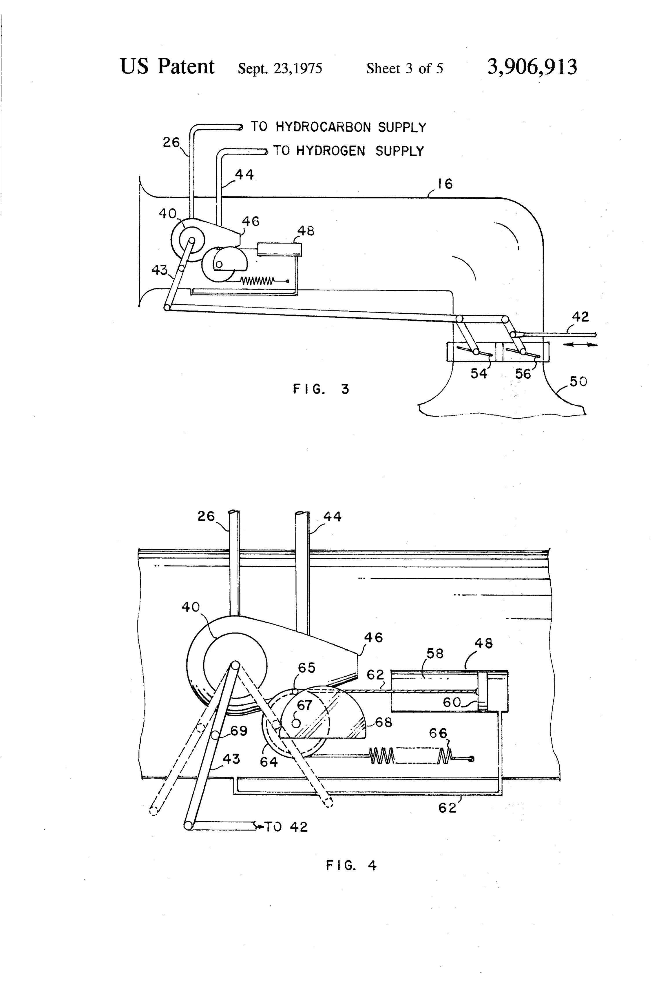
ing higher combustion temperatures thus reducing the quantity of unburned hydrocarbons which are ex FIG. 5 is a view in section illustrating the cam and hausted into the atmosphere. 55 passages within the fuel flow control valve. Mixing hydrogen with a hydrocarbon fuel-air mixture FIG. 6 is a side view of the fuel flow control valve. can extend the flammability limits, but no one has mance bounds FIG. 7 shows a series of curves illustrating the perfor taught how to maintain control at all times when hydro vention. of an engine in accordance with this in gen is used, over an upper and lower boundary on the FIG. 8 is an illustration of a hydrogen generator fuel-air equivalence ratio over the wide range of speed 60 which may be employed with this invention. and lower requirements of an automobile engine. This problem becomes complicated by virture of the fact DESCRIPTION OF THE PREFERRED that a mixture of two (or more) fuels are being used for EMBODIMENT OF THE INVENTION which the "quality' (mass fraction of one fuel in the 65 The curve 8, FIG. 1, represents the characteristic total) of the fuel is constantly changing. The use of a correlation between specific emissions, which here is constant hydrogen flow and unrestricted air flow as NO, and equivalence ratio for a spark internal com taught by the prior art does not solve the problem. bustion engine. This curve can be modified by any one
Page 8
of a number of operating variables, such as spark ad of maximum. This is really just a scaling problem since vance, compression ratio, engine speed, etc., but if one in concept a hydrogen fueled engine could be increased maximizes performance and efficiency of the combus in size to recover the reduced horsepower if that were tion process, and normalizes the NO formation to the deemed essential. It will become apparent however that heat added during each combustion cycle, then the this will not be necessary since an operating system, in dominance of stoichiometry in the correlation of NO accordance with this invention, utilizes this characteris formation is always observed. The curve indicates a tic as a throttling mechanism. characteristic maximum occurring at a location In a particular embodiment of this invention an ar (0.83-0.85 equivalence ratio) which is slightly lean rangement is provided wherein hydrogen or a hydrogen from the stoichiometric mixture, ( 1.0 equivalence ra O rich gas is supplied to an engine as the working fluid of tio). . M a pneumatic atomizer at a quantative rate sufficient to If in an attempt to control NO emissions, one oper supply 100 percent of the energy needs for the engine ates a conventionally fueled engine (e.g., gasoline) very at idle conditions and, by way of illustrating, at an lean, the engine begins to misfire as the engine ap equivalence ratio on the order of 0.15. One of several proaches the flammability limit of the fuel, (0.7 equiva 15 alternate arrangements would provide for a variable lence ratio). Unfortunately this limit occurs for mix hydrogen flow rate (e.g. proportional to engine speed) tures with relatively high NO formation rates and which would decrease the amount of air throttling re therefore imposes severe limitations on the lean limit quired and hence yield slightly higher overall average operation for conventional fuels. On the other hand, operating efficiencies. However, this system would in hydrogen is unique in this regard since it exhibits flam troduce the additional complexity of hydrogen throt mability limits that are only 13 percent of its stoichio tling (as well as air throttling) in order to satisfy the low metric mixture (volume basis). Hence, as indicated in power, high engine speed operating requirements. FIG. 1, it is possible to reduce emissions of NO to es Hence, in illustration of the invention, the preferred sentially zero (less than 1 ppm) simply by using H as embodiment will utilize the constant and minimal hy the fuel and operating at very low equivalence ratios. 25 drogen flow indicated above.
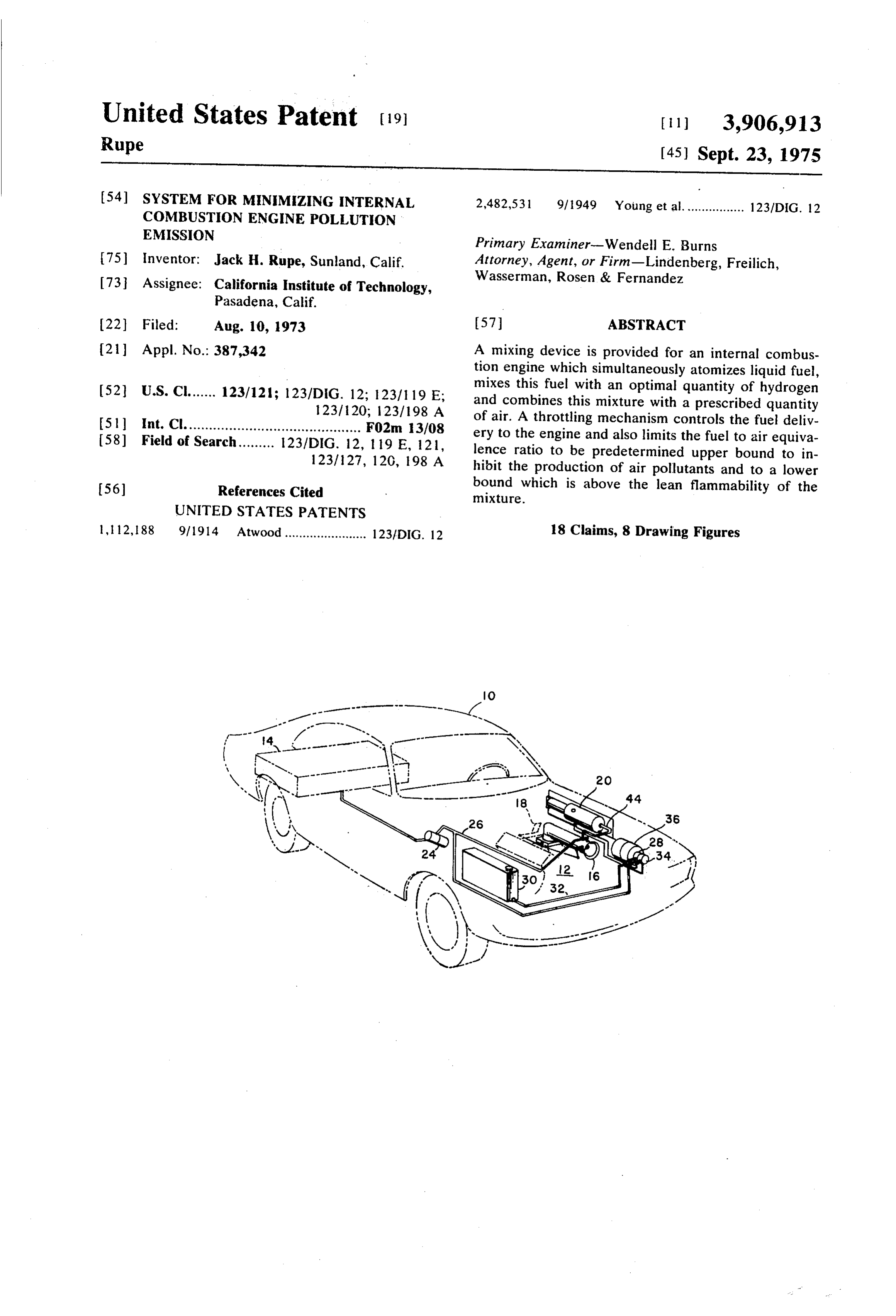
: Insofar as the other emissions are concerned, i.e., CO The pneumatic atomizer is mounted in the intake sys and unburned hydrocarbons, it can be shown that even tem and atomizes the liquid fuel being supplied to the with carbonaceous fuels, operation near the lean flam engine. The liquid fuel delivery system for supplying mability limit is an effective control technique. Obvi fuel to the atomizer is demand controlled to provide ously, if the fuel is 100% H these fuels are not gener 30 varying stoichiometry to the engine. An override of the ated in the combustion process. fuel delivery system, which is air flow sensitive, is pro Thus, in summary, all fuels exhibit similar emission vided to limit the maximum mixture equivalence ratio characteristics, (when properly normalized) which can to a predetermined value - on the order of 0.6 - for ex be reduced to negligible quantities if the combustion ample, in order to minimize NO, formation. process takes place at low equivalence ratios (less than 35 FIG. 2 shows an illustration of an automobile 10, hav 0.6 for example). Since it is now recognized that these ing an engine 12, and a tank 14, in which the hydrocar properties are exhibited by all fuels, it follows that mix bon fuel is kept. In accordance with this invention, the tures of hydrogen and hydrocarbons will behave in a engine is equipped with an induction tube 16, wherein similar manner with reduction in emissions being lim there is located a fuel flow control valve and throttle ited only by the flammability limits of the mixture. override therefore, as well as a pneumatic atomizer, for Thus, the well-known laws for flammability limits of atomizing the fuel and mixing with hydrogen gas. The fuel mixtures serve as the basis for establishing the lean fuel flow control valve is controlled from the foot pedal equivalence ratio bounds that assure flammability by the operator.
while the emission data typified by Curve 8 of FIG. 1 There is also provided an air throttle 18 which is cou serve to establish the upper limit that will be allowed - 45 pled to the fuel flow control valve, and in consonance regardless of engine operating conditions. with fuel flow requirements determines the amount of It has been found that extension of the misfire limits air permitted to flow to the engine through the induc to very lean equivalence ratios with hydrogen fuel also tion tube. The hydrocarbon fuel is fed into the pneu yields significant increases in thermodynamic effi matic atomizer in the induction tube through a pipe 22 ciency of the combustion process. Efficiency is not fuel 50 in which there is a fuel pump 24. dependent and the extension of the misfire limit using The hydrogen rich gas supply for this invention may hydrogen fuel provides efficiency increases of nearly come from any source. Any of the known types of hy 100% relative to the value obtained at the stoichiomet drogen generators may be employed. However, by way ric mixture. Thus, if an engine can be run on hydrogen 55 of example, and not by way of limitation, a hydrogen near its misfire limit, substantial gains in fuel economy generator of the type described and claimed in an ap are possible. plication entitled, "Hydrogen Generator', by House There is a decrease in specific horsepower (horse man, et al., filed Aug. 20, 1973, Ser. No. 390,049, and power for a given engine size) which accompanies the assigned to a common assignee. This hydrogen genera decrease in specific energy (heat release per cycle) 60 tor generates hydrogen rich gas from the hydrocarbon when an engine is operated with a very lean mixture. It fuel used by the engine and water using the steam re has been observed that this property is not fuel depen forming process. A pipe 26 branches from the pipe 22 dent except to limit the operating range (misfire limit) to couple to a pump 28, which is used to supply hydro for carbonaceous fuels. When the operating range is carbon fuel to the hydrogen gas generator 20. A water extended to the misfire limit of hydrogen, (where mini 65 supply coupled to a pump 34 whereby water is pro mum emission and maximum efficiency occur), then vided to the hydrogen generator. An air pump 36, is relative horsepower, (actual horsepower relative to the also employed for applying air under pressure to the maximum attainable at that speed), is reduced to 15% hydrogen generator 20.
Page 9
Referring now to FIG. 3, there is shown an induction and the exterior of the flow control valve 40. The pis tube 16 in section, which, in accordance with this in ton. 60 is attached to a flexible cable 62 which is keyed vention, contains the flow control valve 40, which is to a pulley 64 by a dog 65 and held in tension around controlled by the vehicle operator by means of the the periphery of the pulley by means of a spring 66. The throttle rod 42 and rod coupling 43. Hydrocarbon fuel spring 66 is attached to the wall of the induction tube. is brought to the flow control valve by tube 26 and hy The pulley rotates about a center 67 and rotates with drogen rich gases are brought from a supply, by the it a cam 68. The cam surface can engage a cam fol tube 44. The flow control valve 40 is connected to fuel lower 69, mounted on throttle extension 43 to block atomizer 46. An override control 48 is used to limit the further motion to the right and thus inhibits flow of ad amount of hydrocarbon fuel being supplied by the flow 10 ditional fuel.
control valve for any given engine speed in response to FIG. 4 shows several positions of the extension arm pressure in the venturi which is established by the mass 43, which couples the throttle rod 42 to the flow con air flow to the engine to limit the maximum mixture trol valve 40. The throttle closed position is at the ex ratio to a suitable value for suitably inhibiting the for treme left and is represented by the dotted lines. The mation of NO. The details of the operation of the 15 maximum open throttle at maximum RPM is at the ex override control 48 are discussed in connection with treme right and is represented by the dotted lines. The the description of FIG. 4. solid line position between the two, represents maxi The induction tube is coupled to the engine intake mum throttle at idle RPM. The pressure of the air in the manifold 50, which, because it is so well known, is venturi throat section of the induction tube determines shown as a fragment. The coupling passage between 20 the position of the piston 60. The piston pulls against the induction tube and the intake manifold contains an the spring 66 in response to the vacuum caused by the air throttle section in which two air throttle valves, re venturi and thus, variations in air pressure cause differ spectively 54, 56, are positioned to control the air in ent piston positions which cause rotation of pulley 64 take into the engine, in response to the throttle rod 42 and with it cam 68. In this manner, the position as position, which is positioned by the vehicle operation 25 sumed by the cam is determined by the air pressure or in response to power demands. Two air throttle valves air depression established at the venturi by the air flow are shown by way of example and not by way of limita to the engine. The cam position determines the maxi tion. One or more may be used without departing from mum amount of hydrocarbon fuel which can be pro the spirit or scope of the claims. vided to the engine for any given engine speed. This is The air throttle 54, 56, is actuated in such a way that 30 established in compliance with a predetermined rela the air flow is dictated by a known relation between tionship to the air flow rate. The air flow rate is de gasoline flow rate (set by fuel throttle valve) and the air tected from the static pressure produced in the throat flow in order to assure a mixture bound that is greater of the venturi. By this means, the equivalence ratio of than the lean flammability limit of the fuel mix. As the the fuel plus air mixture can be limited to a selected fuel demand (i.e., power load) decreases at high engine 35 maximum value, which has been found to be on the speeds the fuel flow control valve is driven toward the order of 0.6 at which value production of NO is sub closed position. When this happens the air is also throt stantially eliminated.
tled in order to maintain the fuel-to-air mass flow FIGS. 5 and 6 respectively show a cross-sectional within the prescribed flammability limit. However, in view of the pneumatic atomizer with an integral flow
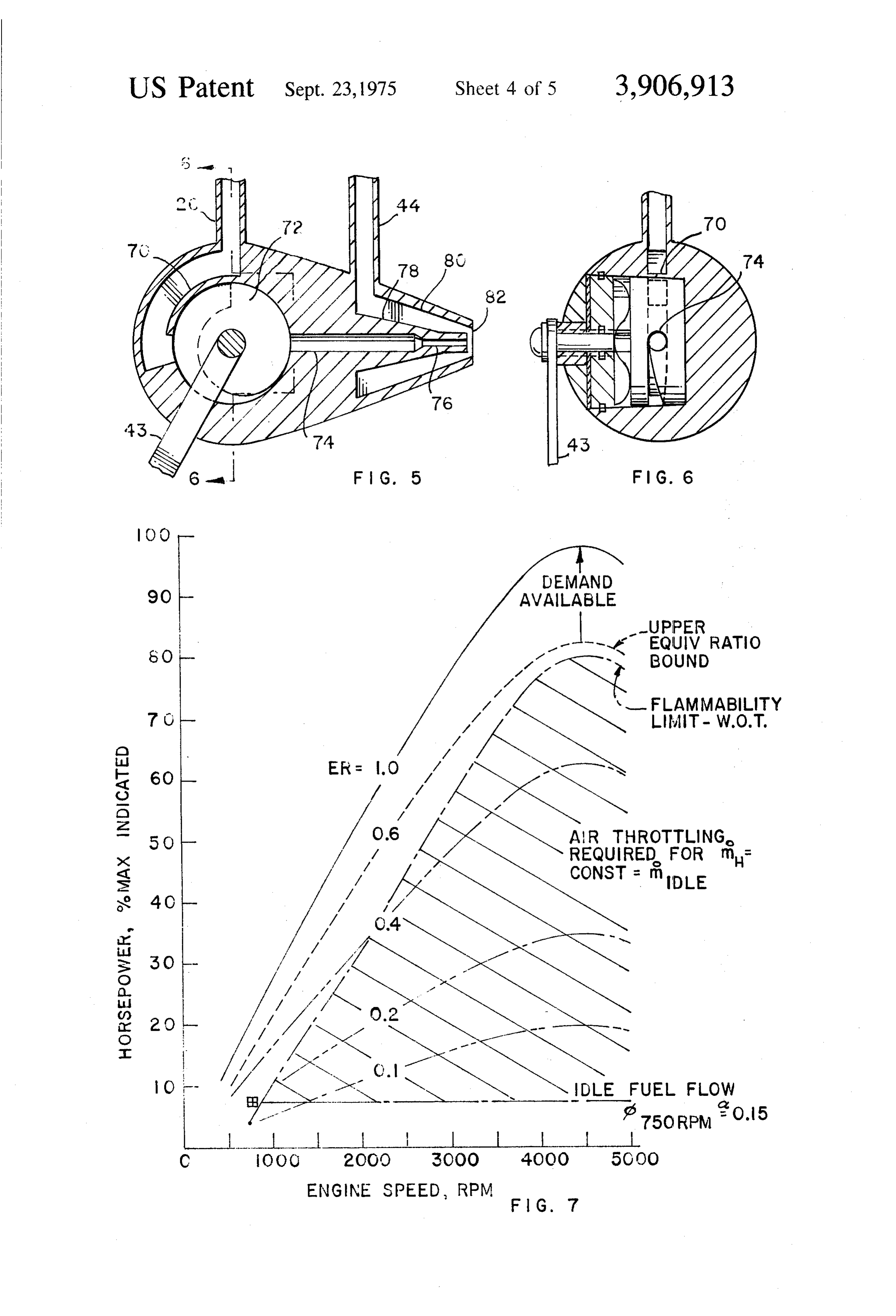
view of the fact that the fuel quality is then dominated control valve and a cross-sectional view along the lines by hydrogen, the engine will operate at very lean 5-5 of FIG. 4. The hydrocarbon fuel line 22 feeds the equivalance ratios. Hence, the throttling requirements fuel into a substantially circular opening, defined by are approximately one-sixth of those needed for con walls 70, within which space a valve member 72, is ro ventional systems. Further, at lessor engine pumping 45 tated by the throttle 43. The opening 70 communicates speeds the need for air throttling is proportionately re with an exit passageway 74, which ends in an exit pas duced. The combination of these effects provide the sage 76, which is considerably narrower than the pas basis for the simple mechanically linked system indi sageway 74.
cated in FIG. 3. The line 24 containing the pneumatic atomizer work The pneumatic atomizer 46 simultaneously mixes the 50 ing fluid communicates with a frustrated conicular re hydrocarbon fuel with the supply of hydrogen rich gion, defined by the walls 78,80, which surrounds the gases and produces a very fine mist. The inducted air exit passageway 76 which is concentric therewith. The mixes with this mist and is urged into the intake mani conicular region terminates in an opening 82. The nar fold and then into the engine. The flow control valve, row exit passageway 76 ends just short of the opening as previously indicated, is demand controlled by the 82, as a result of which the hydrogen gas and the hydro driver using the throttle pedal. The throttle override is 55 carbon fuel spray mix at the exit opening 82 and are used to determine the maximum hydrocarbon fuel flow ejected into the induction passageway of the induction rate so that it is at a value consistent with an upper limit tube.
equivalence ratio of approximately 0.6, which has been: It should be noted that the shape of the valve member determined as the upper bound necessary to best in so 72 is such that when the throttle arm is in the throttle hibit the formation of NO. At idle power requirement closed position, it blocks the passageway 74 and there conditions, no hydrocarbon fuel is employed, the en fore, no hydrocarbon fuel will be supplied to the en gine is then operating on the hydrogen rich gas. gine. The shape of the valve member is contoured to FIG. 4 is a drawing illustrating the details of the over provide a desired rate of flow of hydrocarbon fuel with ride control. The override control includes a chamber throttle position, whereby engine speed may be con 58 containing an air driven piston 60. A tube, 62, con 65 trolled.
nects the top end of the chamber to the throat of the FIG. 7 presents a series of curves illustrating equiva venturi formed between the wall of the induction tube lence ratio, (ER), throttling of a spark ignition engine.
Page 10
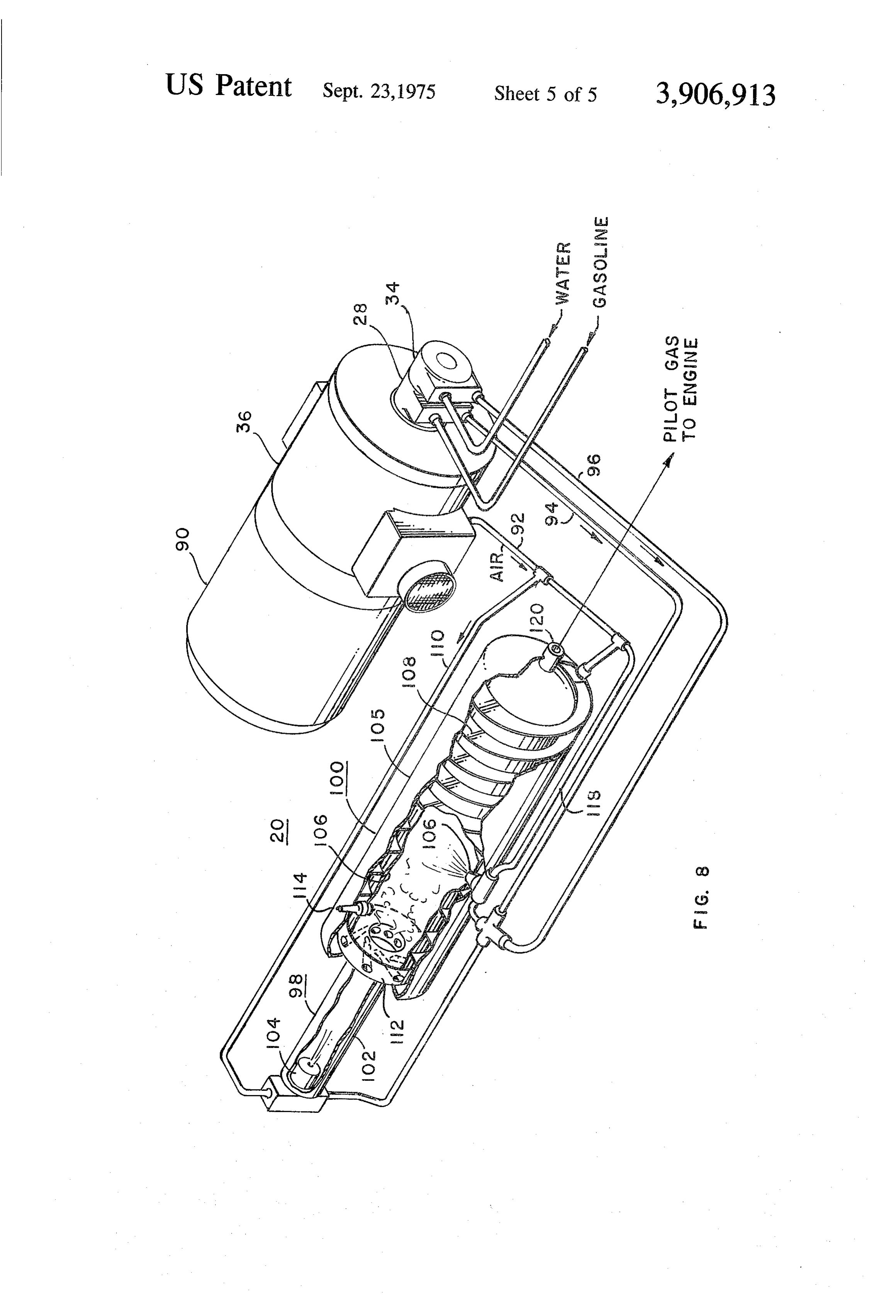
The curves labeled ER=0.1 through 1.0 are for wide there is sprayed a mixture of gasoline and water open throttle operating conditions and assume suffi through a second pneumatic atomizer 116. cient hydrogen available to satisfy the horsepower re The gasoline and water are supplied to the pneumatic quirements illustrated by the 0.1 ER line. These curves atomizer over pipes 94 and 96. High pressure air is also are analogous to a conventional representation where provided as the atomizer working fluid over a pipe 1 18. they would represent mass flow throttling to give re The hot gases in the second chamber convert the spectively 25, 35, 63, 87, and 97 percent of the maxi water spray in the fuel-water mixture into steam. The mum power available at any given engine speed. It is fuel is vaporized and a steam reforming action takes seen that with equivalence ratio throttling, engine place within the reactor space formed by the burning power is varied on demand by varying fuel flow while O chamber. Hydrogen rich gas passes out of the opening equivalence ratio is allowed to vary with either fuel 120 to the induction tube of the engine. flow or engine speed. In conventional engines, power For start up, the vehicle ignition switch will also ener is adjusted by changing the mass density of the combus gize the motor 90 which causes delivery of air to the hy tion charge (and hence energy) for a substantially con drogen generator. After a suitable delay interval to stant mixture ratio. Superimposed on this operating 15 allow air pressure to build up to a predetermined value. map is the flammability limit curve which bounds the such as 5 psi, or when the pressure is sensed by a pres cross hatched region where air throttling is required sure sensitive switch, the engine cranking system is ac when the hydrogen flow is constant and equal to idle tivated, the engine and hydrogen generator ignition sys energy requirements. In this system, the engine burns tems are activated and the magnetic clutch that couples a fuel that is "pure’ hydrogen at idle and a fuel that is the water and fuel pumps, respectively 34, 28, to the a mixture of perhaps 90% liquid fuel and 10% hydrogen motor drive are activated. This produces hydrogen sub at maximum horsepower, (also maximum equivalence stantially instantaneously and the engine then boot ratio and high engine speed), condition. For the low straps itself to the idle condition.
load conditions where the bulk of the driving is done, 25 There has accordingly been described and shown it is estimated that the fuel mixture would vary between herein a novel and useful system for operating an inter 5 and 25% hydrogen and hence emissions and effi nal combustion engine in a manner to substantially ciency tend to be simultaneously optimized. eliminate combustion products which cause air pollu FIG. 8 is a drawing illustrating a hydrogen gas gener tion, while effectively reducing the amount of hydro ator which may be employed to provide hydrogen rich 30 carbon fuel which is consumed.
gas to an engine, in accordance with this invention. In the foregoing application, and in the claims, it This is shown by way of illustration of hydrogen rich should be understood that the word “hydrogen' is used gas and not by way of limitation. An electric motor 90 as an abbreviation for “hydrogen rich gas.' The inven drives an air pump 36, a gasoline pump 28 and a water tion does not require pure hydrogen gas. The hydrogen pump 34 to provide these fluids to the gas generator 20 35 rich gas may contain considerable fractions of inert and over the respective pipes 92, 94 and 96. The hydrogen flamnable material.
rich gas generator includes two portions respectively What is claimed is:
98 and 100 which include chambers which have the 1. A system for minimizing the air pollution output of same axis and communicate at one end with each an internal combustion engine comprising other. 40 an induction system for said engine having means for The first portion has cylindrical walls 102 which en mixing a hydrogen rich gas, a liquid fuel and air; close a first chamber. At one end of this chamber is a means for controlling said means for mixing over the pneumatic atomizer 104 to which air, as the operating operating range of said engine to provide a gas, fuel fluid, and the hydrocarbon fuel are supplied to atomize and air mixture in proportions within predeter the fuel. The air is supplied directly from the high pres 45 mined upper and lower equivalence ratio bounds sure discharge of the air pump 36. and yet are within the flammable range of said mix The second portion 100 of the hydrogen generator ture which minimize air pollution by said engine, has outer cylindrical walls 105. These enclose inner cy and lindrical walls, which are spaced therefrom and define means for applying the output of said means for mix a second chamber, which is the burning chamber. Be 50 ing to said internal combustion engine. tween the first and second walls is a spiral wall 108, 2. A system as recited in claim 1 wherein said means which defines a spiral passage. Air is pumped into one for mixing includes a pneumatic atomizer for atomizing end of the spiral passage over the pipe 92, to be di fuel and mixing fuel with hydrogen rich gas, and rected around the inner walls 106 and thus, is pre air valve means for controlling the amount of air per heated by the inner chamber walls which surround the 55 mitted to flow to said internal combustion engine burning chamber. together with said mixture of fuel and gas. The fuel-air mixture created in the first chamber is 3. A system as recited in claim 2 wherein said means passed into the second chamber through an air swirler. for controlling said means for mixing includes a throttle This comprises a toroid with a plurality of passages 60 controlled fuel control valve means for controlling the which are angularly directed from the outer periphery amount of fuel supplied to said pneumatic atomizer, of the toroid ring to the central opening. Preheated air means for sensing the mass air flow to said engine and from the spiral passage passes through these angularly producing a representative control effect, and directed openings and causes the air-fuel mixture pass override means responsive to said mass air flow con ing through the central opening of the air swirler 112 trol effect for limiting to a predetermined value the to be swirled as it enters into the burning chamber. A maximum amount of fuel supplied by said flow spark plug 114 ignites this mixture and the hot gases control valve to said pneumatic atomizer over the which are created pass further into the chamber where operating range of said engine.
Page 11
4. A system as recited in claim 3, wherein said means predetermined maximum opening which is corre for sensing the mass air flow to said engine and produc lated to engine speed.
ing a representative control effect, includes 9. A system as recited in claim 6 wherein said over an induction tube for supplying air to the manifold of ride means for limiting the maximum amount of fuel
4. 5 passed by said fuel supply control means includes means for establishing a venturi in said induction walls defining a chamber, tube, and , a piston within said chamber, means for measuring pressure variations of the air air passage means for enabling air pressure communi passing through said venturi and producing a con cation between said chamber and said air venturi, trol effect responsive thereto. 10 for determining the position of said piston respon 5. A system as recited in claim 1 wherein said means sive to said air pressure, and for controlling controls said means for mixing to pro means responsive to the position of said piston for duce, over the operating range of said engine, a gas, preventing operation of said valve means to in fuel and air mixture which is within the flammable crease the flow of hydrocarbon fuel through said range for the mixture and which does not exceed an 15 fuel supply control system beyond a predetermined upper bound equivalence ratio of approximately 0.6. maximum amount as specified for each engine 6. A system for minimizing the air pollution output of speed.
an internal combustion engine, comprising 10. In an internal combustion engine a system for an induction system including walls defining an air eliminating noxious emissions from said engine com induction tube, said induction tube being coupled prising to the manifold of said internal combustion engine, a source of hydrocarbon fuel, a fuel supply control system positioned within said a source of hydrogen rich gas, induction tube and dimensioned to form an air ven an induction system including an air intake induction turi with the induction tube walls adjacent thereto, tube, means for supplying hydrocarbon fuel to said fuel 25 said tube containing throttle controlled fuel supply supply control system, means, means for supplying hydrogen rich gas to said fuel means establishing a venturi passage within the walls supply control system, of said induction tubes, valve means in said fuel supply control system for pipe means for bringing said hydrocarbon fuel and controlling the amount of hydrocarbon fuel permit 30 said hydrogen rich gas from said source of hydro ted to pass through said fuel control system, carbon fuel and said source of hydrogen to said said fuel supply control system further including throttle controlled fuel supply means, means for mixing and emitting hydrocarbon fuel said throttle controlled fuel supply means including and hydrogen gas into said induction tube, - wall means forming a pneumatic atomizer for at override means responsive to air pressure caused by 35 omizing said hydrocarbon fuel and mixing it with mass air flow through said venturi for limiting the said hydrogen rich gas to form a fuel mixture, amount of hydrocarbon fuel that can be passed override control means responsive to the pressure in through said fuel control system to a predeter said venturi passage established within said induc mined value, and tion tube for limiting to a predetermined maximum throttle control means, operative in conjunction with 40 amount for each specified engine speed the amount said valve means for controlling the amount of air of hydrocarbon fuel supplied by said throttle con passing from said induction tube into said engine trolled fuel supply means, intake manifold to maintain a fuel-air mixture ratio means coupling said induction tube to said engine, which minimizes the air pollution output of said en 45 and gine. a throttle controlled means in said means coupling 7. A system as recited in claim 6 wherein said means said induction tube to said engine for controlling for mixing and emitting hydrocarbon fuel and hydrogen the air supplied thereto to maintain the mixture gas into said induction tube comprises ratio of the fuel mixture to air at all times within the a pneumatic atomizer, flammable range of the fuel mixture to air and not means for supplying hydrocarbon fuel from said 50 to exceed an upper bound of approximately 0.6.
valve means to said pneumatic atomizer, and 11. In an internal combustion engine as recited in means for supplying said hydrogen rich gas to said claim 10 wherein said throttle controlled fuel supply pneumatic atomizer as a working fluid to mix said means includes a variable area fuel control valve for hydrocarbon fuel as a fine mist with said gas. supplying hydrocarbon fuel to said pneumatic atom 8. A system as recited in claim 6 wherein said valve 55 izer, means in said fuel supply control means for controlling movable throttle rod means for controlling said vari the amount of hydrocarbon fuel passing therethrough able area fuel control valve for determining the includes amount of hydrocarbon fuel flow to said pneumatic walls defining a substantially circular cavity, atomizer.
a fuel entrance passageway at one side of said cavity, 60 12. In an internal combustion engine as recited in a fuel exit passageway at another side of said cavity, claim 11 wherein said variable area fuel control valve and includes means for closing off the hydrocarbon fuel a rotatable throttle control cam means for establish supplied to said pneumatic atomizer when said mov ing the size of the passageway through said circular able throttle rod means assumes an engine idle posi cavity between said entrance passageway and said 65 tion.
exit passageway from a blocked position when said 13. In an internal combustion engine as recited in engine is producing idle power requirements to a claim 10 wherein said override control means includes
Page 12
walls defining a chamber, of an internal combustion engine comprising the steps a piston means within said chamber, of . . .
air passage means for enabling air pressure communi over the operating ranger of said engine mixing, cation between said chamber and said venturi pas within said engine, induction system, air, hydrocar sage for determining the position of said piston 5 bon fuel and hydrogen rich gas, means responsive to said air pressure, controlling said mixing to provide a fuel-air mixture a cam means having a can surface, and ratio that is within the flammable range for the mix means for moving said cam means surface against ture and does not exceed a selected upper bound said throttle rod means responsive to motion of equivalence ratio of approximately 0.6, and said piston means to establish maximum motion of 10 supplying said mixture to said engine. said movable throttle rod means to limit hydrocar 16. A method as recited in claim 15 wherein said step bon fuel flow to a predetermined maximum value of mixing said air, hydrocarbon fuel and hydrogen rich for any given pressure in said venturi passage. gas includes 14. In an internal combustion engine, an induction supplying in predetermined quantities the amount of system for providing a hydrogen rich gas, hydrocarbon 15 hydrocarbon fuel to be mixed with said hydrogen fuel and air mixture to said engine to minimize the air rich gas responsive to a throttle control, pollutants produced by said engine comprising mixing said hydrocarbon fuel which is supplied with throttle controlled valve means for measuring the said hydrogen rich gas, quantity of hydrocarbon fuel provided for said mix mixing said mixture of hydrogen rich gas and hydro ture, 20 carbon fuel with said air, and override control means for establishing the maximum controlling the amount of air mixed to provide said amount of said hydrocarbon fuel provided by said fuel-air mixture ratio that is within the flammable throttle control means for said mixture consistant range for the mixture and does not exceed a se with an upper equivalence ratio of approximately lected upper bound equivalance ratio of approxi 0.6 over the operating range of said engine, 25 mately 0.6.
pneumatic atomizer means for mixing hydrogen rich 17. A method as recited in claim 16 wherein said step gas with the output of said throttle controlled of supplying predetermined quantities of hydrocarbon means to provide a mixed fuel, fuel includes throttle controlled air valve means for determining limiting the maximum amount of hydrocarbon fuel the amount of air mixed with said fuel mixture at 30 provided over the operating range of said engine a value which assures a combustible mixed fuel-air responsive to the mass airflow to said engine. mixture under all operating conditions including 18. A method as recited in claim 15 wherein said step high speed, light load engine and operating condi of controlling said mixing provides only a mixture of a tions. hydrogen rich gas and air when said engine is idling. 15. A method of minimizing the air pollution output 35 k - k is
Provenance
- Collection
- Cited prior art
- Original PDF
- patentimages.storage.googleapis.com →
- Filed
- 1973-08-10
- Pages
- 12
- Method
- pdftotext (the PDF's own text layer) + pdftoppm 300dpi page scans
- Source
- Google Patents bibliographic record
- Granted
- 1975-09-23
- Inventors
- Jack H Rupe; California Institute of Technology
- Transcribed from
- patentimages.storage.googleapis.com →